DFI G586IPV User manual

G586IPV/E
Rev. C+
System Board
User’s Manual
- 32561003 -

FCC Statement on Class B
This equipment has been tested and found to comply with the limits for
a Class B digital device, pursuant to Part 15 of the FCC rules. These
limits are designed to provide reasonable protection against harmful in-
terference when the equipment is operated in a residential installation.
This equipment generates, uses and can radiate radio frequency energy
and, if not installed and used in accordance with the instruction manual,
may cause harmful interference to radio communications. However,
there is no guarantee that interference will not occur in a particular in-
stallation. If this equipment does cause harmful interference to radio or
television reception, which can be determined by turning the equipment
off and on, the user is encouraged to try to correct the interference by
one or more of the following measures:
•Reorient or relocate the receiving antenna.
•Increase the separation between the equipment and the receiver.
•Connect the equipment into an outlet on a circuit different from that
to which the receiver is connected.
•Consult the dealer or an experienced radio TV technician for help.
Notice:
1.The changes or modifications not expressly approved by the party
responsible for compliance could void the user's authority to oper-
ate the equipment.
2.Shielded interface cables must be used in order to comply with the
emission limits.
The manufacturer makes no warranties with respect to this documenta-
tion and disclaims any implied warranties of merchantability, quality, or
fitness for any particular purpose. The information in this document is
subject to change without notice. The manufacturer reserves the right to
make revisions to this publication and to make changes to any and/or
all parts of its content, at any time, without obligation to notify any per-
son or entity of such changes. Further, the manufacturer assumes no
responsibility for any errors that may appear in this document.

Table of Contents
Chapter 1: Introduction............................................................ 4
Features and Specifications.................................................. 4
Package Checklist .............................................................. 5
Chapter 2: Hardware Installation............................................... 6
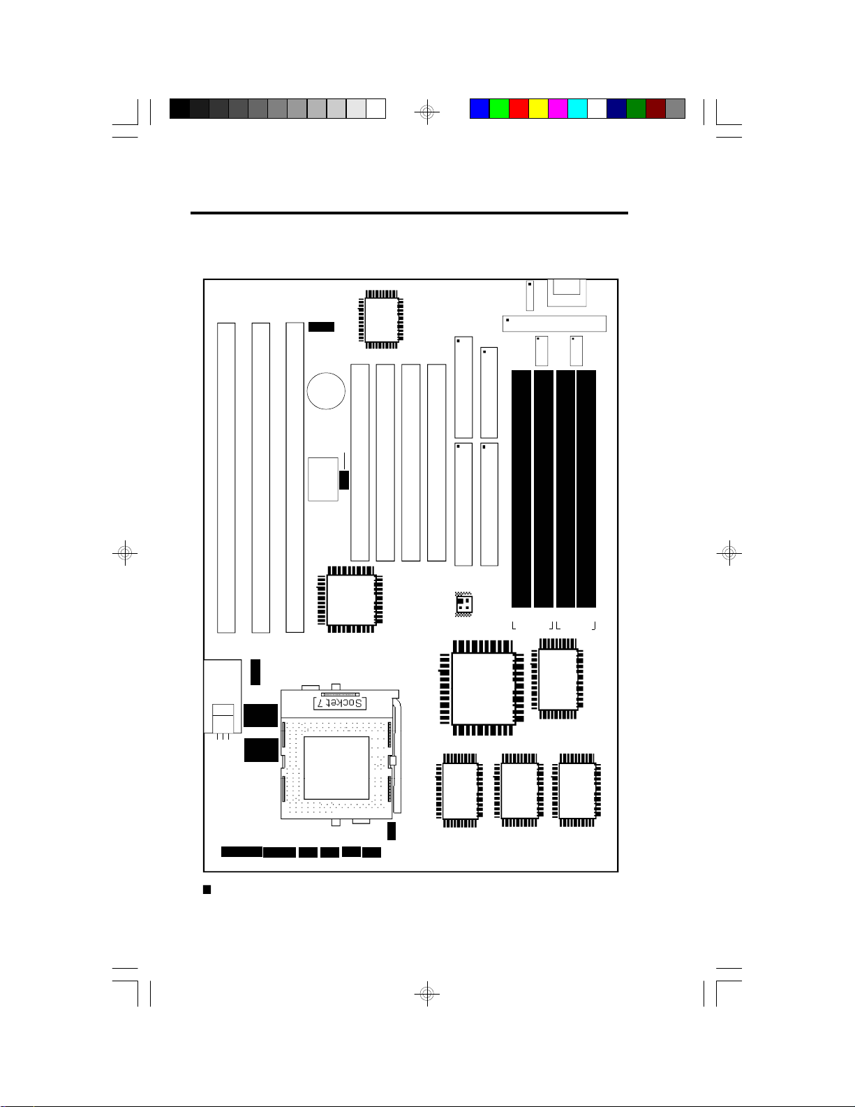
Board Layout ..................................................................... 6
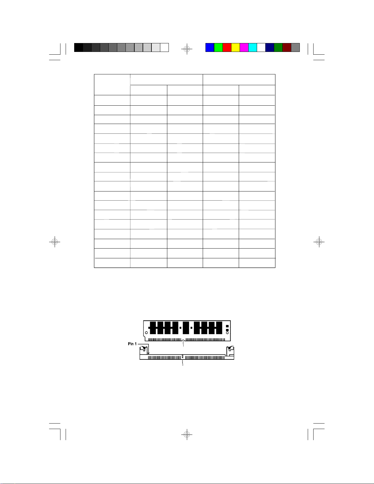
System Memory................................................................. 7
Cache Memory.................................................................. 9
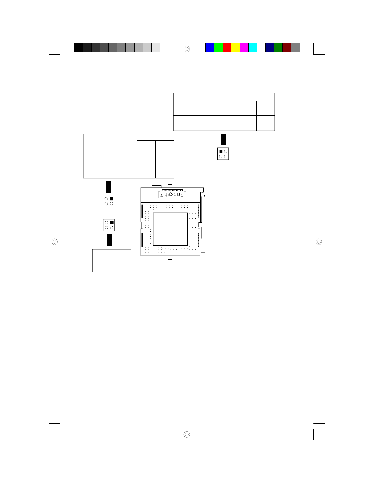
CPU Installation................................................................. 9
Jumper Settings for CMOS Clear..........................................16
Jumper Settings for Display Type...........................................16
Built-in Ports.....................................................................17
Installing Expansion Cards...................................................20
Chapter 3: Software Installation...............................................21
Award BIOS CMOS Setup Utility...........................................21
Standard CMOS Setup..................................................22
BIOS Features Setup....................................................26
Chipset Features Setup.................................................30
Power Management Setup.............................................31
PNP/PCI Configuration Setup..........................................34
Load BIOS Defaults......................................................35
Load Setup Defaults.....................................................35
Integrated Peripherals...................................................36
Supervisor Password....................................................37
User Password............................................................38
IDE HDD Auto Detection................................................39
HDD Low Level Format .................................................41
Save & Exit Setup........................................................41
Exit Without Saving.......................................................41
System Error Report ..........................................................42
IDE Device Drivers.............................................................43
Appendix A: Types of Modules......................................................44
Appendix B: Memory and I/O Maps................................................45
Appendix C: Connector................................................................47

4
Features and Specifications
Processor
•IntelPentium75/90/100/120/133/150/166/200MHz
•Cyrix6x86 P120+/ P133+/ P150+/P166+
•AMD-K5™ PR75/PR90/PR100
Chipset
•Intel 82430VX PCIset
Cache Memory
•256KB or 512KB pipeline burst, direct map write-back cache
installed on the system board
System Memory
•8MB to 128MB memory
•Four 72-pin SIMM sockets
•Uses EDO or fast page mode x32 DRAM, 60ns or 70ns, 5V
BIOS
•Award BIOS, Windows 95 Plug andPlay compatible
•Flash EPROM for easy BIOS upgrades
Energy Efficient Design
•System power management supported
•CPU stopped clock control
•Hardware supports SMI green mode
•Microsoft/Intel APM compliant
•External power management switch supported
PCI IDE Interface
•PIO Mode 3 and Mode 4 Enhanced IDE (data transfer rate up to
16.6MB/sec.)
•DMA Mode 2 Bus Master IDE (data transfer rate up to 22.2MB/sec.)
•Bus mastering reduces CPU utilization during disk transfer
•ATAPI IDE CD-ROM supported
Chapter 1
Introduction

5
Integrated I/O
•Two NS16C550A-compatible high speed UARTs
•One SPP/ECP/EPP parallel port
•Supports 360KB, 720KB, 1.2MB, 1.44MB, and 2.88MB floppy drives
•Two Universal Serial Bus connectors supported in future revision
CPU Socket
•321-pin ZIF socket (Intel Socket 7)
Connectors
•2 serial ports
•1 parallel port
•2 IDE connectors
•1 floppy connector
•1 PS/2 mouse port
•1 AT keyboard connector
Expansion Slots
•4 dedicated PCI slots and 3 dedicated 16-bit ISA slots
PCB
•4 layers, Baby AT form factor
•25cm (9.84") x 22cm (8.66")
Package Checklist
The G586IPV/E package contains the following items:
•The G586IPV/E system board
•The G586IPV/E user’s manual
•One 40-pin IDE hard disk cable
•One 34-pin floppy disk drive cable
•One 25-pin printer port cable
•Two serial port cables
•One mouse port cable
•One IDE driver diskette
•Five jumper caps
If any of these items are missing or damaged, please contact your
dealer or sales representative for assistance.

6
Chapter 2
Hardware Installation
Bank 1
Board Layout
square denotes pin 1
PBSRAM = Pipeline Burst SRAM
PCI Slot 4
PCI Slot 3
PCI Slot 2
PCI Slot 1
J6:FDC
J7:PrinterJ8: Primary IDE
J9: Secondary IDE
PL1
ISA Slot 1
ISA Slot 2
ISA Slot 3
CN1CN2
JP3
JP5
J10
JP8
JP9
Intel
SB82371SB
I/O Chip
J3
SM4
SM3
SM2
SM1
Bank 0
COM 2
COM 1
BIOS
PBSRAM
32kx32
PBSRAM
32kx32
Intel 82437VX
Intel 82438VX
Intel 82438VX
Battery
J15
J16J17
J18
J13J14Pin 1
JP6
U23U22
J5J4
- +
- +
U25

7
System Memory
The SIMM (Single In-line Memory Module) sockets are divided into two
banks on the system board, Bank 0 and Bank 1. Each bank consists of
2 SIMM sockets. Refer to page 6 for the locations of the SIMM sockets.
You will need either 2 or 4 pieces of SIM modules, depending on the
amount of memory you intend to install. The system board will not work
if you install 1 or 3 pieces. Make sure you insert the same type of
SIMMs in one bank. You can install SIMMs in either of the banks, Bank
0 or Bank 1, but you must populate one bank first before going to the
next bank.
The G586IPV/E system board can support 8MB to 128MB of memory
using 1MBx32, 2MBx32, 4MBx32, or 8MBx32 72-pin SIMMs. The table
below shows the supported SIM modules and their corresponding
memory sizes.
SIMMs
1MBx32
2MBx32
4MBx32
8MBx32
Memory Size
4MB
8MB
16MB
32MB
The table below summarizes the bank locations and modules needed for
the corresponding memory sizes.
MemorySize
8MB
8MB
16MB
16MB
16MB
Bank0
SIMM1
1MBx32
—
2MBx32
—
1MBx32
SIMM2
1MBx32
—
2MBx32
—
1MBx32
SIMM4
—
1MBx32
—
2MBx32
1MBx32
Bank1
SIMM3
—
1MBx32
—
2MBx32
1MBx32

8
SIMM2
1MBx32
2MBx32
4MBx32
2MBx32
1MBx32
4MBx32
2MBx32
4MBx32
8MBx32
—
4MBx32
1MBx32
8MBx32
2MBx32
8MBx32
4MBx32
8MBx32
8MBx32
SIMM1
1MBx32
2MBx32
4MBx32
2MBx32
1MBx32
4MBx32
2MBx32
4MBx32
8MBx32
—
4MBx32
1MBx32
8MBx32
2MBx32
8MBx32
4MBx32
8MBx32
8MBx32
MemorySize
24MB
24MB
32MB
32MB
40MB
40MB
48MB
48MB
64MB
64MB
64MB
72MB
72MB
80MB
80MB
96MB
96MB
128MB
Bank0
SIMM4
2MBx32
1MBx32
—
2MBx32
4MBx32
1MBx32
4MBx32
2MBx32
—
8MBx32
4MBx32
8MBx32
1MBx32
8MBx32
2MBx32
8MBx32
4MBx32
8MBx32
Bank1
SIMM3
2MBx32
1MBx32
—
2MBx32
4MBx32
1MBx32
4MBx32
2MBx32
—
8MBx32
4MBx32
8MBx32
1MBx32
8MBx32
2MBx32
8MBx32
4MBx32
8MBx32
Installing a SIM Module
A SIM module simply snaps into a socket on the system board. Pin 1 of
the SIM module must correspond with Pin 1 of the socket.
notch
key

9
CPU Installation
The G586IPV/E allows for easy installation of CPUs. Make sure all
jumpers are set correctly before applying power or you may damage the
CPU or system board. Please see the jumper settings on the following
pages. Use the needle-nosed pliers to move the jumpers if necessary.
The table below shows the External Bus Clock of the CPUs supported by
the G586IPV/E system board and their corresponding PCI Clock and Bus
Clock.
Cache Memory
The G586IPV/E system board can support 256KB or 512KB pipeline
burst, direct map write-back cache SRAM installed at locations U22 and
U23 of the system board. Refer to page 6 for the locations of the
SRAMs.
1.Position the SIMM above the socket with the “notch” in the module
aligned with the “key” on the socket.
2.Seat the module at a 45° angle into the bank. Make sure it is com-
pletely seated. Tilt the module upright until it locks in place in the
socket.
External Bus Clock
50MHz
55MHz
60MHz
66MHz
PCI CLK
25MHz
27.5MHz
30MHz
33MHz
Bus CLK
8.333MHz
9.1666MHz
7.5MHz
8.25MHz

10
Intel CPUs
75/90/100MHz
120/133MHz
150/166MHz
200MHz
Freq.
Ratio
1.5x
2x
2.5x
3x
Pin 1-2
Off
On
On
Off
Pin 3-4
Off
Off
On
On
JP8
JP8
2
1
4
3
JP9
2
1
4
3
* Default
Voltage
3.3V*
3.5V
JP9
1-2 On
3-4 On
Intel CPUs
75MHz
90/120/150MHz
100/133/166/200MHz
Ext. Bus
CLK
50MHz
60MHz
66MHz
Pin 1-2
On
On
Off
Pin 3-4
On
Off
On
JP6
Warning:
The default setting of JP9 is 3.3V. If
the voltage of your CPU is not 3.3V,
make sure you set JP9 according to
the voltage of your CPU, otherwise,
your system will hang.
Jumper Settings for Intel CPUs
4
2
3
1JP6

11
Jumper Settings for Cyrix 6x86 CPUs
Cyrix CPUs
P120+/P133+/
P150+/P166+
Freq.
Ratio
2xPin 1-2
OnPin 3-4
Off
JP8
JP8
2
1
4
3
JP9
2
1
4
3
* Default
Voltage
3.3V*
3.5V
JP9
1-2 On
3-4 On
Cyrix CPUs
P120+
P133+
P150+
P166+
Ext. Bus
CLK
50MHz
55MHz
60MHz
66MHz
Pin 1-2
On
Off
On
Off
Pin 3-4
On
Off
Off
On
JP6
Warning:
The default setting of JP9 is 3.3V. If
the voltage of your CPU is not 3.3V,
make sure you set JP9 according to
the voltage of your CPU, otherwise,
your system will hang.
4
2
3
1JP6

12
Jumper Settings for AMD-K5 CPUs
AMD-K5 CPUs
PR75 75MHz
PR90 90MHz
PR100 100MHz
Freq.
Ratio
1.5xPin 1-2
OffPin 3-4
Off
JP8
JP8
2
1
4
3
JP9
2
1
4
3
* Default
Voltage
3.3V*
3.5V
JP9
1-2 On
3-4 On
AMD-K5 CPUs
PR75 75MHz
PR90 90MHz
PR100 100MHz
Ext. Bus
CLK
50MHz
60MHz
66MHz
Pin 1-2
On
On
Off
Pin 3-4
On
Off
On
JP6
Warning:
The default setting of JP9 is 3.3V. If
the voltage of your CPU is not 3.3V,
make sure you set JP9 according to
the voltage of your CPU, otherwise,
your system will hang.
4
2
3
1JP6

13
To install an upgrade CPU, do the following:
1.To raise the handle, push it down, slightly pull it out to the side,
then raise it as far as it will go. It may be necessary to initially apply
a small amount of sideways force to free the handle from its retain-
ing “tab”. Once clear of the “tab”, the handle will open relatively
easily. The top plate will slide back.
Zero Insertion Force (ZIF) Socket
Installing Upgrade CPUs
The G586IPV/E is equipped with a 321-pin Zero Insertion Force (ZIF)
socket at location U25 of the system board. Refer to page 6 for the
location of the ZIF socket. This socket is designed for easy removal of
an old CPU and easy insertion of an upgrade CPU. The ZIF socket
allows you to carefully place the new CPU into its position. If you need
to apply excessive force to insert the CPU, you are not installing the
CPU correctly.
Warning:
Open the socket only if you are actually installing a CPU. The warranty
on the original CPU will be voided if the S/N seal is broken. Before
proceeding with the upgrade, take note of the following. The micropro-
cessor and heatsink may be hot if the system has been running. To
avoid the possibility of a burn, power the system off and let the proces-
sor and heatsink cool for 20 minutes.
The 321-pin ZIF socket consists of five rows of pin holes on each side.
To prevent improper CPU installation, the ZIF socket has a Plug/Keying
mechanism. Several holes in the socket are plugged so that the CPU
will go in only one way.

14
Lifting the Handle
2.Once the lever is completely up, remove the old CPU carefully by
lifting it straight out of the socket. You are now ready to insert the
new CPU.
3.Position the CPU above the ZIF socket. Make sure pin 1 of the
CPU is aligned with pin 1 of the socket. Lower the chip until the
pins are inserted properly in their corresponding holes. Remember
that very little force is needed to install the CPU. If the CPU is not
easily inserted, verify whether or not pin 1 of the CPU is aligned
with pin 1 of the socket. Applying too much pressure can damage
the CPU or the socket.

15
4.Push the handle down until the handle locks into place. The top
plate will slide forward. You will feel some resistance as the pres-
sure starts to secure the CPU in the socket. This is normal and will
not damage the CPU. However, if the handle is not completely
closed, damage to the CPU and/or system board may result.
Installing A Fan/Heatsink for Cyrix CPUs
If you are using a Cyrix CPU, you must choose a fan/heatsink which is
made for Cyrix processors. Position the fan/heatsink on the CPU such
that the air from the side of the fan/heatsink will flow across the heat
regulator on the system board. See the figure below.
Positioning the CPU Above the ZIF Socket

16
Jumper Settings for Display Type
Jumper JP3
Display Type Select
Jumper JP3 sets the display adapter to color or mono. This jumper
must match the type of display adapter installed. If you change your
video adapter, make sure this jumper is changed accordingly.
Clearance Requirements
Your CPU comes with a heatsink mounted on top. To maintain proper
airflow once the upgrade is installed on the system board, the CPU and
heatsink require certain space clearances.
The clearance above the CPU’s fan/heatsink must be at least 0.4
inches. The clearance on at least 3 of 4 sides of the processor and
heatsink must be at least 0.2 inches. All cables (for floppy drive, hard
drive, CD-ROM, etc.) must be routed clear of the CPU and its airspace.
Fan Exhaust
The CPU must be kept cool by using a fan with heatsink. The tempera-
ture of the air entering the fan/heatsink cannot exceed 45oC (113oF).
The ambient or room temperature must be below 37oC (99oF).
Jumper Settings for CMOS Clear
Jumper JP5
CMOS Clear
If, for some reason, the CMOS becomes corrupted, the system can be
reconfigured with the default values stored in the ROM BIOS. To load
the default values, power off your system and set JP5 to On. Then
power on your system for 5 seconds and turn it off again. Set JP5 back
to its default setting, Off.
Off:Normal(default)On:CMOSClear

17
Serial Ports
The built-in serial ports are RS-232C asynchronous communication
ports with 16C550A-compatible UARTs that can be used with modems,
serial printers, remote display terminals, and other serial devices. They
use the following system I/O addresses:
Built-in Ports
The G586IPV/E system board is equipped with two serial ports, one
parallel printer port, one FDD connector, two IDE hard disk connectors
and one PS/2 mouse connector. Refer to page 6 for the locations of the
built-in connectors and pin 1 of those connectors.
Port Configuration
Serial Port 1
Serial Port 2
COM1
3F8h*
3F8h
COM2
2F8h
2F8h*
COM3
3E8h
3E8h
COM4
2E8h
2E8h
* Default
2-3On:Mono
1-2On:Color
(default)
3 2 13 2 1
Connecting the Serial Ports
Two serial port cables mounted on a card-edge bracket are provided
with the system board. Connect one serial port cable to connector J4
for COM 1 primary serial port and the other serial port cable to connec-
tor J5 for COM 2 secondary serial port. Make sure the colored stripes
on the ribbon cables are aligned with pin 1 of connectors J4 and J5.
Mount the card-edge bracket to the system chassis.
PS/2 Mouse Port
The PS/2 mouse port is a 6-pin connector on the system board. Attach
the 6-pin mouse port cable, which is mounted on a card-edge bracket,

18
Connecting the Parallel Printer Port
Attach the DB-25 printer cable, which came with the system board, to
connector J7 on the G586IPV/E system board. Make sure the colored
stripe on the ribbon aligns with pin 1 of connector J7. Use a small
nutdriver to mount the cable into a DB-25 cutout in the system chassis.
If your printer port cable is attached to a card-edge bracket, connect the
cable to connector J7 on the system board and mount the card-edge
bracket to the system chassis.
Floppy Disk Drive Controller
The G586IPV/E system board has a built-in floppy disk controller that
supports two standard floppy disk drives. You can install any 360KB,
720KB, 1.2MB, 1.44MB, or 2.88MB floppy disk drives.
Connecting the Floppy Disk Cable
1.Install the 34-pin header connector into the floppy disk connector
(J6) on the system board. The colored edge of the ribbon should be
aligned with pin 1 of connector J6.
2.Install the other 34-pin header connector(s) into the disk drive(s).
Align the colored edge of the daisy chained ribbon cable with pin 1
of the drive edge connector(s). The end-most connector should be
attached to the drive you want to designate as Drive A.
I/O Address3BC-3BE Hex
378-37A Hex (default)
278-27A Hex
to connector J3. Make sure the red wire on the PS/2 mouse connector
is aligned with pin 1 of connector J3.
Parallel Port
The G586IPV/E system board has a standard connector for interfacing
your PC to a parallel printer. The parallel port on your system board can
be set to any of the following system I/O addresses:

19
IDE Hard Disk Interface
The G586IPV/E system board is equipped with two PCI IDE connectors
that will interface four Enhanced IDE (Integrated Drive Electronics) hard
disk drives.
Note:
Only Enhanced IDE hard drives or ATAPI CD-ROMs can be connected
to the IDE interface.
Connecting the Hard Disk Cable
1.If you are connecting two hard drives, install the 40-pin connector of
the IDE cable into the primary IDE connector (connector J8). If you
are adding a third or fourth IDE device, install the 40-pin connector
of the other IDE cable into the secondary IDE connector (connector
J9).
2.Install the other 40-pin header connector(s) into the device with the
colored edge of the ribbon cable aligned with pin 1 of the drive
edge connector(s).
Note:
Refer to your disk drive user’s manual for information about selecting
proper drive switch settings.
Adding a Second IDE Hard Drive
When using two IDE drives, one must be set as the master and the
other as the slave. Follow the instructions provided by the drive manu-
facturer for setting the jumpers and/or switches on the drives.
We recommend that the Enhanced IDE hard drives be from the same
manufacturer. In a few cases, drives from two different manufacturers
will not function properly when used together. The problem lies in the
hard drives, not the G586IPV/E system board.

20
Important:
If you encountered problems while using an ATAPI CD-ROM drive that
is set in Master mode, please set the CD-ROM drive to Slave mode.
Some ATAPI CD-ROMs may not be recognized and cannot be used if
incorrectly set to Master mode.
Installing Expansion Cards
The G586IPV/E system board is equipped with 4 dedicated PCI slots
and 3 dedicated 16-bit ISA slots. All PCI slots are bus masters. Refer to
page 6 for the locations of the expansion slots. Due to the size of the
CPU with its accompanying fan/heatsink component, the length of the
add-in cards in PCI slot 4 and ISA slot 1 is limited to 18cm (7.07",
measured from the bracket of the card).
Other manuals for G586IPV
4
This manual suits for next models
1
Table of contents
Other DFI Motherboard manuals