E-XTEQ DCBS User manual

INTERACTIVE NAVIGATION
DCBS
USER MANUAL
MANUAL / Reference : MAN_DCBS_E-XTEQ_EN_V1.0
Measurement Global Solutions
E-XTEQ provides International engineering / OEM’s worldwide connections / High capacity production.
HIGH-TECH INDUSTRIES: RESEARCH & DEVELOPMENT, ASSEMBLY LINES, WORKSHOPS
E-XTEQ USA T.: (877) 453 3265 lE-XTEQ EUROPE T.: +33 01 30 07 13 30 lE-XTEQ.COM

2/52
DCBS User Manual / Ref. MAN_DCBS_GM_EN_V1.0
Introduction................................................................................................. 3
Safety Guidelines......................................................................................... 4
Maintenance and Storage................................................................................... 4
Before Use ........................................................................................................... 4
Usage Precautions............................................................................................... 5
Disassembly/Damage/Removal.......................................................................... 5
Cleaning the Product .......................................................................................... 5
Getting Started ........................................................................................... 6
Safety Reminders ................................................................................................ 6
Appearance and Dimensions.............................................................................. 6
Trolley LED’s ........................................................................................................ 7
Remote Presentation........................................................................................... 7
Remote Job Storage ........................................................................................... 8
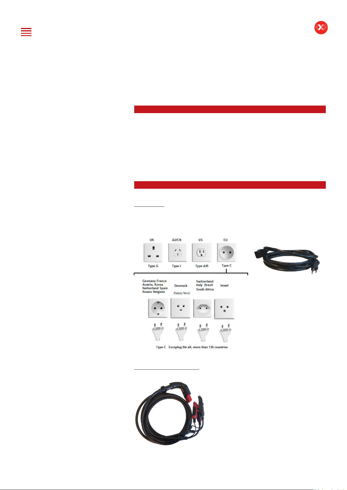
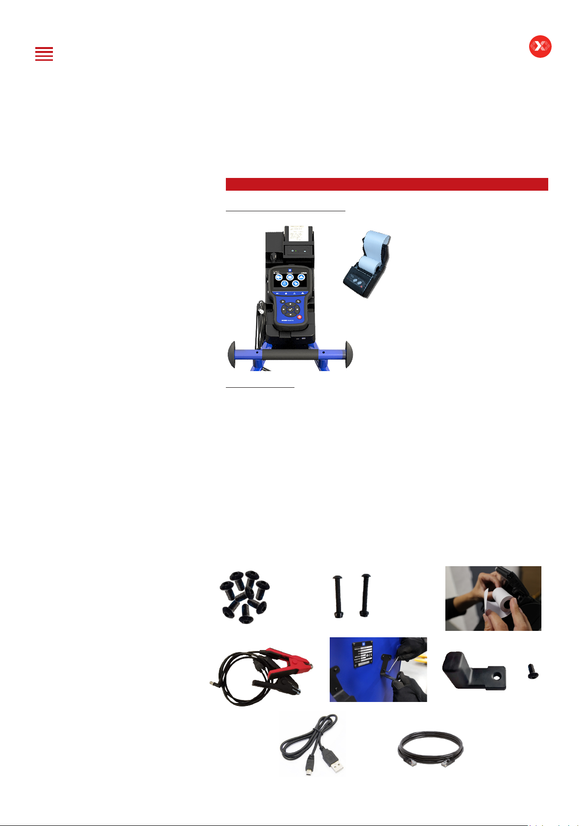
Accessories .......................................................................................................... 8
Initial Setup................................................................................................ 10
Installation ......................................................................................................... 10
Battery Cable Clamps Connection....................................................................11
Power Cable Connection and Power On ..........................................................11
Wi-Fi Connection (Remote to Trolley Only) ......................................................12
Dealer Identication Number (Business Associate Code) ...............................13
Update ................................................................................................................13
Settings.......................................................................................................17
Preferences.........................................................................................................17
Wi-Fi Connection (Remote to net) ................................................................... 18
Other settings ................................................................................................... 19
Diagnostic and Charge.............................................................................. 20
Remote handheld diagnostic tester ......................................................... 20
-Vehicle Selection from Database .................................................................... 20
-Manual Selection of Battery............................................................................ 23
-Start Diagnostic & Results............................................................................... 24
Trolley Diagnostic...................................................................................... 26
-Complete Diagnostic & Results ...................................................................... 26
-Charge & Results.............................................................................................. 29
-Load Test & Results.......................................................................................... 32
-Reserve Capacity Test & Results..................................................................... 35
Result storage............................................................................................ 38
Optimus ..................................................................................................... 40
-Optimus installation......................................................................................... 40
-Using Optimus ................................................................................................. 43
Support Information.................................................................................. 45
Warranty.................................................................................................... 47
Table of Contents
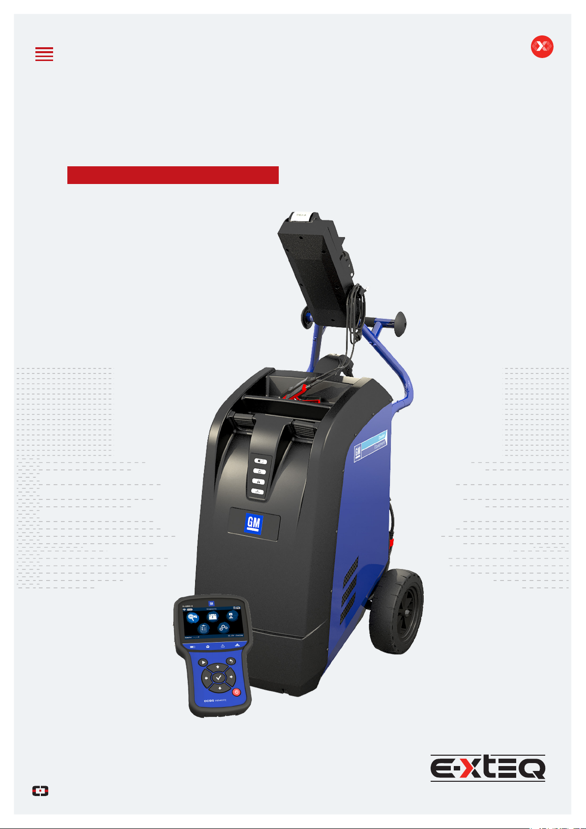
E-XTEQ DCBS USER MANUAL
Revision of the manual
Due to software updates, your experience of the software interface (including but not limited to software features, user interfaces, and
interaction experiences) may differ from the interface presented in this manual. The software interface is subject to change.
ÉDITION / REVISION REFERENCE DATE UPDATES PARTS
First edition MAN_DCBS_GM_EN_V1.0 January 2020 -
Second edition MAN_DCBS_GM_EN_V1.1 September 2022 Software update/Physical connection upgrade
Table of Content
Introduction
Safety Guidelines
Maintenance and Storage
Before Use
Usage Precautions
Disassembly/Damage/Removal
Cleaning the Product
Getting Started
Safety Reminders
Appearance and Dimensions
Trolley LED’s
Remote Presentation
Remote Job Storage
Accessories
Initial Setup
Installation
Battery Cable Clamps Connection
Power Cable Connection and Power On
Dealer Id. N°
Wi-Fi Connection (Remote to Trolley)
Physical Connection (Remote to Trolley)
Update
Settings
Preferences
Other Settings
Diagnostic and Charge
Remote handheld diagnostic tester
-Manual Selection of Battery
-Vehicle Selection from Database
-Start Diagnostic & Results
Trolley Diagnostic
-Complete Diagnostic & Results
-Pre Delivery Inspection Test (PDI) & Results
-Charge & Results
-Load Test & Results
-Enhanced Diagnostic Mode (EDM) & Results
-Reserve Capacity Test & Results
History (Results Storage)
Optimus
-Optimus Installation
-Using Optimus
Support Information
-Batteries
-Error Messages
Warranty

3/52
DCBS User Manual / Ref. MAN_DCBS_GM_EN_V1.0
Introduction
ABOUT ////////
E-XTEQ is a battery diagnostic tool and equipment manufacturer with a broad
spectrum of knowledge and understanding of battery technology for Industrial,
OE and Aftermarket Maintenance including EV/HEV applications.
Our mission is to be a passionate global leader of innovative measurement solutions
by providing premium testing equipment and unsurpassed services to our valued
customers and partners.
The GM DCBS supports battery diagnostic tests including functional true ½ CCA
load test and provides a reserve capacity test. DCBS has built-in 12V/100A battery
charger/maintainer that provides in-depth features and functions to stabilize battery
voltage during ECU reashing and is capable of charging different chemistry
batteries.
The remote is a comprehensive battery analyzer with intuitive features and functions
that promotes user friendliness, speed, accuracy and intelligence, enabling
technicians to manage diagnostics through every step of the process from start to
nish and can be used simultaneously.
Table of Content
Introduction
Safety Guidelines
Maintenance and Storage
Before Use
Usage Precautions
Disassembly/Damage/Removal
Cleaning the Product
Getting Started
Safety Reminders
Appearance and Dimensions
Trolley LED’s
Remote Presentation
Remote Job Storage
Accessories
Initial Setup
Installation
Battery Cable Clamps Connection
Power Cable Connection and Power On
Dealer Id. N°
Wi-Fi Connection (Remote to Trolley)
Physical Connection (Remote to Trolley)
Update
Settings
Preferences
Other Settings
Diagnostic and Charge
Remote handheld diagnostic tester
-Manual Selection of Battery
-Vehicle Selection from Database
-Start Diagnostic & Results
Trolley Diagnostic
-Complete Diagnostic & Results
-Pre Delivery Inspection Test (PDI) & Results
-Charge & Results
-Load Test & Results
-Enhanced Diagnostic Mode (EDM) & Results
-Reserve Capacity Test & Results
History (Results Storage)
Optimus
-Optimus Installation
-Using Optimus
Support Information
-Batteries
-Error Messages
Warranty

4/52
DCBS User Manual / Ref. MAN_DCBS_GM_EN_V1.0
Safety Guidelines 1/2
Please read the safety guidelines carefully.
This section indicates the areas that need to be protected in order to prevent harm
to people who use this equipment, damage to property and to enable proper use
of this product.
MAINTENANCE AND STORAGE ////////
Keep this product dry. Do not expose the DCBS to rain or snow.
Discontinue use and contact technical support if an overheat event has occurred,
or if corrosion or deterioration has been identied in the cables or other parts of the
product.
BEFORE USE ////////
Keep the exterior clean and free of dust.
Do not disassemble or modify the main unit
as it may cause an electrical shortage or re.
To reduce the risk of electrical shortage, unplug the
AC power plug before cleaning and maintenance.
Extreme caution: Keep liquids and conductive tools away from the DCBS while
operating.
DCBS must be used in a well-ventilated area.
When operating the equipment make sure the surface is dry and clean to minimize
any risks.
The battery contains chemicals that may generate
explosive gases. Before handling the battery,
remove all metal accessories such as rings, bracelets
and necklaces. Short circuit at battery terminals may
cause burns. Do not place batteries near ames or
other heat sources.
The battery uid is highly corrosive. If the battery uid
gets on your skin or clothes, immediately wash it with
soap and water. If electrolyte gets in your eyes, immediately
ush with cold water for at least 10 minutes and seek
medical attention.
Table of Content
Introduction
Safety Guidelines
Maintenance and Storage
Before Use
Usage Precautions
Disassembly/Damage/Removal
Cleaning the Product
Getting Started
Safety Reminders
Appearance and Dimensions
Trolley LED’s
Remote Presentation
Remote Job Storage
Accessories
Initial Setup
Installation
Battery Cable Clamps Connection
Power Cable Connection and Power On
Dealer Id. N°
Wi-Fi Connection (Remote to Trolley)
Physical Connection (Remote to Trolley)
Update
Settings
Preferences
Other Settings
Diagnostic and Charge
Remote handheld diagnostic tester
-Manual Selection of Battery
-Vehicle Selection from Database
-Start Diagnostic & Results
Trolley Diagnostic
-Complete Diagnostic & Results
-Pre Delivery Inspection Test (PDI) & Results
-Charge & Results
-Load Test & Results
-Enhanced Diagnostic Mode (EDM) & Results
-Reserve Capacity Test & Results
History (Results Storage)
Optimus
-Optimus Installation
-Using Optimus
Support Information
-Batteries
-Error Messages
Warranty

5/52
DCBS User Manual / Ref. MAN_DCBS_GM_EN_V1.0
Safety Guidelines 2/2
USAGE PRECAUTIONS ////////
Do not use extension cords as there is a risk of re and electrical shortage.
If use is necessary, check that the extension cord has the following:
1. Identical plug, cable size and the same electrical wiring as the DCBS.
2. Make sure the equipment is securely connected before use.
When unplugging the cord from the outlet, hold the frame of the plug to avoid
damaging the plug or power cord. Pulling the cord may cause the cable plug
to break. Replace power cord immediately if damaged.
If the outlet shape does not t the plug, please contact the E-XTEQ service
department.
Phone: 1.877.453.3265
E-mail: support.usa@e-xteq.com
Do not touch the power connector during use.
Keep away and Do Not Touch restricted areas
of this equipment.
DISASSEMBLY/DAMAGE/REMOVAL ////////
Do not disassemble the product or damage or remove the stickers or labels on the
product. If the product’s case has been disassembled or damaged by the user, all
warranties will be void. Always contact a designated E-XTEQ Service Center for
repairs.
Do not insert metallic objects into the unit to prevent electric shock, re, short
circuit, possible leaking of harmful substances and personal injuries. Do not store
the product in a wet or humid place. Always store the product in a dry place.
CLEANING THE PRODUCT ////////
It is recommended that you clean the product by wiping it gently using a soft cloth.
Do not use water, chemical substances or detergents. They may cause discoloration
or corrosion to the product’s exterior and may cause a re or electric shock.
Table of Content
Introduction
Safety Guidelines
Maintenance and Storage
Before Use
Usage Precautions
Disassembly/Damage/Removal
Cleaning the Product
Getting Started
Safety Reminders
Appearance and Dimensions
Trolley LED’s
Remote Presentation
Remote Job Storage
Accessories
Initial Setup
Installation
Battery Cable Clamps Connection
Power Cable Connection and Power On
Dealer Id. N°
Wi-Fi Connection (Remote to Trolley)
Physical Connection (Remote to Trolley)
Update
Settings
Preferences
Other Settings
Diagnostic and Charge
Remote handheld diagnostic tester
-Manual Selection of Battery
-Vehicle Selection from Database
-Start Diagnostic & Results
Trolley Diagnostic
-Complete Diagnostic & Results
-Pre Delivery Inspection Test (PDI) & Results
-Charge & Results
-Load Test & Results
-Enhanced Diagnostic Mode (EDM) & Results
-Reserve Capacity Test & Results
History (Results Storage)
Optimus
-Optimus Installation
-Using Optimus
Support Information
-Batteries
-Error Messages
Warranty

6/52
DCBS User Manual / Ref. MAN_DCBS_GM_EN_V1.0
Getting Started 1/4
SAFETY REMINDERS ////////
Please review the safety guidelines in this manual before using the DCBS for safety
operations
When unplugging the DCBS, pull on the plug frame rather than the cord to reduce
the risk of damaging the power plug or cord.
The DCBS is designed for indoor use. Use outside in dry weather only.
The GM DCBS enables a wide range diagnostic procedures with 0-15V/0-80A
(100A Optional) charge capability.
APPEARANCE AND DIMENSIONS ////////
Dimension Details: Weight:
Metrics: 1300 x 580 x 690 (mm) Kilogram: 67 (kg)
Imperial: 51.18 x 22.83 x 27.16 (inch) Pounds: 148 (lbs.)
Width
22.83in / 58cm
Depth
27.16in / 69cm
Height
51.18in / 103cm
Table of Content
Introduction
Safety Guidelines
Maintenance and Storage
Before Use
Usage Precautions
Disassembly/Damage/Removal
Cleaning the Product
Getting Started
Safety Reminders
Appearance and Dimensions
Trolley LED’s
Remote Presentation
Remote Job Storage
Accessories
Initial Setup
Installation
Battery Cable Clamps Connection
Power Cable Connection and Power On
Dealer Id. N°
Wi-Fi Connection (Remote to Trolley)
Physical Connection (Remote to Trolley)
Update
Settings
Preferences
Other Settings
Diagnostic and Charge
Remote handheld diagnostic tester
-Manual Selection of Battery
-Vehicle Selection from Database
-Start Diagnostic & Results
Trolley Diagnostic
-Complete Diagnostic & Results
-Pre Delivery Inspection Test (PDI) & Results
-Charge & Results
-Load Test & Results
-Enhanced Diagnostic Mode (EDM) & Results
-Reserve Capacity Test & Results
History (Results Storage)
Optimus
-Optimus Installation
-Using Optimus
Support Information
-Batteries
-Error Messages
Warranty

7/52
DCBS User Manual / Ref. MAN_DCBS_GM_EN_V1.0
Getting Started 2/4
APPE
TROLLEY LED’S ////////
ARANCE AND DIMENSIONS
REMOTE PRESENTATION ////////
1. Charge – The Charge LED will blink during
diagnostic and charge operations.
2. Wi-Fi Connection (Remote to Trolley only) –
The Wi-Fi connection LED will turn GREEN once
connection is established
or turn RED if connection is lost.
3. Status – If the Status LED is RED, the trolley has
encountered an error.
4. Load Test –The Load Test LED will blink BLUE
during a Load Test and a Reserve Capacity Test.
1
2
3
4
1
23
4
56
7 8 9 10
11 12
13
14
15
16
1
2
3
4
5
6
7
8
9
10
11
12
13
IR Thermometer
Connection to Trolley
Remote Battery Status
Remote Clamps Connection Port
Remote Connection Voltage Display
Trolley Connections Voltage
Display
Diagnostic/Charge Indicator
Trolley Connection Indicator
Error Mode Indicator
Load Test Indicator
Star t Test
Cancel, Previous Step
OK, Next Step
Navigation Arrows
Power On/Off
Ethernet Port for Physical Connection
14
15
16
Table of Content
Introduction
Safety Guidelines
Maintenance and Storage
Before Use
Usage Precautions
Disassembly/Damage/Removal
Cleaning the Product
Getting Started
Safety Reminders
Appearance and Dimensions
Trolley LED’s
Remote Presentation
Remote Job Storage
Accessories
Initial Setup
Installation
Battery Cable Clamps Connection
Power Cable Connection and Power On
Dealer Id. N°
Wi-Fi Connection (Remote to Trolley)
Physical Connection (Remote to Trolley)
Update
Settings
Preferences
Other Settings
Diagnostic and Charge
Remote handheld diagnostic tester
-Manual Selection of Battery
-Vehicle Selection from Database
-Start Diagnostic & Results
Trolley Diagnostic
-Complete Diagnostic & Results
-Pre Delivery Inspection Test (PDI) & Results
-Charge & Results
-Load Test & Results
-Enhanced Diagnostic Mode (EDM) & Results
-Reserve Capacity Test & Results
History (Results Storage)
Optimus
-Optimus Installation
-Using Optimus
Support Information
-Batteries
-Error Messages
Warranty

8/52
DCBS User Manual / Ref. MAN_DCBS_GM_EN_V1.0
Getting Started 3/4
REMOTE JOB STORAGE ////////
The remote has expandable storage through an SD card located on the right side
of the tool inside the rubber protective boot.
The tool will come with a 16 GB removable SD card.
Acceptable sizes for replacements are 4GB, 8GB and 16GB formatted with FAT32 le
system.
ACCESSORIES ////////
Power Cord
16.4 ft/5m power cord is supplied with the GM DCBS.
*The cord will be suitable based on the destination country standards*
Charge Cable with Clamp
The cable will be used for trolley diagnostic
and charging.
Table of Content
Introduction
Safety Guidelines
Maintenance and Storage
Before Use
Usage Precautions
Disassembly/Damage/Removal
Cleaning the Product
Getting Started
Safety Reminders
Appearance and Dimensions
Trolley LED’s
Remote Presentation
Remote Job Storage
Accessories
Initial Setup
Installation
Battery Cable Clamps Connection
Power Cable Connection and Power On
Dealer Id. N°
Wi-Fi Connection (Remote to Trolley)
Physical Connection (Remote to Trolley)
Update
Settings
Preferences
Other Settings
Diagnostic and Charge
Remote handheld diagnostic tester
-Manual Selection of Battery
-Vehicle Selection from Database
-Start Diagnostic & Results
Trolley Diagnostic
-Complete Diagnostic & Results
-Pre Delivery Inspection Test (PDI) & Results
-Charge & Results
-Load Test & Results
-Enhanced Diagnostic Mode (EDM) & Results
-Reserve Capacity Test & Results
History (Results Storage)
Optimus
-Optimus Installation
-Using Optimus
Support Information
-Batteries
-Error Messages
Warranty

9/52
DCBS User Manual / Ref. MAN_DCBS_GM_EN_V1.0
Getting Started 4/4
ACCESSORIES ////////
Docking Station with Printer
Accessories Box
1. 8 Short Screws
2. 2 Long Screws
3. Printer Paper Roll
4. 1.5mm Specic Remote Clamps
5. 2 Hooks (For Rear of the Trolley)
6. 1 Hook (Docking Station)
7. USB Cable
8. Ethernet Cable (For Physical Connection)
2. 3.
1.
6.
5.
4.
7. 8.
Table of Content
Introduction
Safety Guidelines
Maintenance and Storage
Before Use
Usage Precautions
Disassembly/Damage/Removal
Cleaning the Product
Getting Started
Safety Reminders
Appearance and Dimensions
Trolley LED’s
Remote Presentation
Remote Job Storage
Accessories
Initial Setup
Installation
Battery Cable Clamps Connection
Power Cable Connection and Power On
Dealer Id. N°
Wi-Fi Connection (Remote to Trolley)
Physical Connection (Remote to Trolley)
Update
Settings
Preferences
Other Settings
Diagnostic and Charge
Remote handheld diagnostic tester
-Manual Selection of Battery
-Vehicle Selection from Database
-Start Diagnostic & Results
Trolley Diagnostic
-Complete Diagnostic & Results
-Pre Delivery Inspection Test (PDI) & Results
-Charge & Results
-Load Test & Results
-Enhanced Diagnostic Mode (EDM) & Results
-Reserve Capacity Test & Results
History (Results Storage)
Optimus
-Optimus Installation
-Using Optimus
Support Information
-Batteries
-Error Messages
Warranty

10/52
DCBS User Manual / Ref. MAN_DCBS_GM_EN_V1.0
Initial Setup 1/8
INSTALLATION ////////
The unit needs to be placed in a clean, dry and ventilated area.
Tools necessary to assemble trolley:
- 4mm Allen Wrench, 10mm Socket/Wrench. (Step 3, use long screws)
- 3mm Allen Wrench. (Step 4, use short screw)
Once the unit is out of the box, the next step is to connect the docking station
to the trolley.
Then install the remote clamps hook and install the printer and the paper.
To use the remote by itself, connect the clamps on the side of the remote.
1.
3.
5.
2.
4.
6.
Caution: Insert screw carefully in step 3 to not damage cable with screw inside tube.
Table of Content
Introduction
Safety Guidelines
Maintenance and Storage
Before Use
Usage Precautions
Disassembly/Damage/Removal
Cleaning the Product
Getting Started
Safety Reminders
Appearance and Dimensions
Trolley LED’s
Remote Presentation
Remote Job Storage
Accessories
Initial Setup
Installation
Battery Cable Clamps Connection
Power Cable Connection and Power On
Dealer Id. N°
Wi-Fi Connection (Remote to Trolley)
Physical Connection (Remote to Trolley)
Update
Settings
Preferences
Other Settings
Diagnostic and Charge
Remote handheld diagnostic tester
-Manual Selection of Battery
-Vehicle Selection from Database
-Start Diagnostic & Results
Trolley Diagnostic
-Complete Diagnostic & Results
-Pre Delivery Inspection Test (PDI) & Results
-Charge & Results
-Load Test & Results
-Enhanced Diagnostic Mode (EDM) & Results
-Reserve Capacity Test & Results
History (Results Storage)
Optimus
-Optimus Installation
-Using Optimus
Support Information
-Batteries
-Error Messages
Warranty

11/52
DCBS User Manual / Ref. MAN_DCBS_GM_EN_V1.0
Initial Setup 2/8
BATTERY CABLE CLAMPS CONNECTION ////////
Remove the battery cable clamps from the box to connect them through the
connector in the rear of the DCBS Trolley.
POWER CABLE CONNECTION AND POWER ON ////////
Input power information
Voltage 100 – 240 V
Frequency 50/60 Hz
Consumption 2 kW Maximum
Connect the power cord to the connector located on the back of the DCBS, then
connect the opposite plug to a standard electrical socket. Switch on the device by
setting the switch to the “I” position.
Table of Content
Introduction
Safety Guidelines
Maintenance and Storage
Before Use
Usage Precautions
Disassembly/Damage/Removal
Cleaning the Product
Getting Started
Safety Reminders
Appearance and Dimensions
Trolley LED’s
Remote Presentation
Remote Job Storage
Accessories
Initial Setup
Installation
Battery Cable Clamps Connection
Power Cable Connection and Power On
Dealer Id. N°
Wi-Fi Connection (Remote to Trolley)
Physical Connection (Remote to Trolley)
Update
Settings
Preferences
Other Settings
Diagnostic and Charge
Remote handheld diagnostic tester
-Manual Selection of Battery
-Vehicle Selection from Database
-Start Diagnostic & Results
Trolley Diagnostic
-Complete Diagnostic & Results
-Pre Delivery Inspection Test (PDI) & Results
-Charge & Results
-Load Test & Results
-Enhanced Diagnostic Mode (EDM) & Results
-Reserve Capacity Test & Results
History (Results Storage)
Optimus
-Optimus Installation
-Using Optimus
Support Information
-Batteries
-Error Messages
Warranty

12/52
DCBS User Manual / Ref. MAN_DCBS_GM_EN_V1.0
Initial Setup 3/8
DEALER ID NUMBER ////////
After trolley has been setup, turn on the remote and follow the steps below to input
the Dealer ID Number into the tool. (This number is required to generate warranty
code).
BAC will be recorded, no need to re-enter after initial setup.
1. Go to the Settings Menu. 2. Go to the Information Icon.
3. Go to the BAC (Business Association
Code) Icon.
4. Input Dealer ID Number and Press
Enter, then Back to Save.
Table of Content
Introduction
Safety Guidelines
Maintenance and Storage
Before Use
Usage Precautions
Disassembly/Damage/Removal
Cleaning the Product
Getting Started
Safety Reminders
Appearance and Dimensions
Trolley LED’s
Remote Presentation
Remote Job Storage
Accessories
Initial Setup
Installation
Battery Cable Clamps Connection
Power Cable Connection and Power On
Dealer Id. N°
Wi-Fi Connection (Remote to Trolley)
Physical Connection (Remote to Trolley)
Update
Settings
Preferences
Other Settings
Diagnostic and Charge
Remote handheld diagnostic tester
-Manual Selection of Battery
-Vehicle Selection from Database
-Start Diagnostic & Results
Trolley Diagnostic
-Complete Diagnostic & Results
-Pre Delivery Inspection Test (PDI) & Results
-Charge & Results
-Load Test & Results
-Enhanced Diagnostic Mode (EDM) & Results
-Reserve Capacity Test & Results
History (Results Storage)
Optimus
-Optimus Installation
-Using Optimus
Support Information
-Batteries
-Error Messages
Warranty

13/52
DCBS User Manual / Ref. MAN_DCBS_GM_EN_V1.0
Initial Setup 4/8
WI-FI CONNECTION (REMOTE TO TROLLEY ONLY) ////////
This setting is to connect the Remote to the Trolley via Wi-Fi only. Physical
connection via Ethernet cable will not work if the Wi-Fi setting is used. If
the wireless connection between the Remote and Trolley is not stable due
to Electromagnetic Interference, please use physical connection option
explained below.
1. Turn on the Remote and go to the
“Settings” icon.
2. Go to the “Wireless” icon.
3. Select “Trolley connection” Icon
5. Select “Bar-code Scan” for the
tool to scan the trolley serial number
or “Manual” to manually input the
trolley serial number.
6. The Serial Number can be found
on the back of the trolley. Refer to
picture for visual conrmation.
4.Select your preferred Wi-Fi
Frequency. (If this option is not available,
continue to step 5)
Table of Content
Introduction
Safety Guidelines
Maintenance and Storage
Before Use
Usage Precautions
Disassembly/Damage/Removal
Cleaning the Product
Getting Started
Safety Reminders
Appearance and Dimensions
Trolley LED’s
Remote Presentation
Remote Job Storage
Accessories
Initial Setup
Installation
Battery Cable Clamps Connection
Power Cable Connection and Power On
Dealer Id. N°
Wi-Fi Connection (Remote to Trolley)
Physical Connection (Remote to Trolley)
Update
Settings
Preferences
Other Settings
Diagnostic and Charge
Remote handheld diagnostic tester
-Manual Selection of Battery
-Vehicle Selection from Database
-Start Diagnostic & Results
Trolley Diagnostic
-Complete Diagnostic & Results
-Pre Delivery Inspection Test (PDI) & Results
-Charge & Results
-Load Test & Results
-Enhanced Diagnostic Mode (EDM) & Results
-Reserve Capacity Test & Results
History (Results Storage)
Optimus
-Optimus Installation
-Using Optimus
Support Information
-Batteries
-Error Messages
Warranty

14/52
DCBS User Manual / Ref. MAN_DCBS_GM_EN_V1.0
Initial Setup 5/8
PHYSICAL CONNECTION (REMOTE TO TROLLEY ONLY) ////////
1. Turn on the Remote and go to the
“Settings” icon.
2. Go to the “Wireless” icon.
3. Select the “OFF” Icon
5. Ensure the Ethernet Cable is
connected to the trolley and remote as
shown
4. The Wi-Fi logo will dissapear from
the top of the screen
6. Verify connection by connecting a
battery and conrming the voltage at
bottom right
NOTE: Trolley and Remote will communicate only through the physical
connection between them. Restart of Trolley and Remote may be required
for proper physical connection communication.
UPDATE ////////
Optimus software
DCBS is delivered with a Software Installation Guide (OPTIMUS).
Optimus connection is mandatory for product update, and also useful for data
(history) storage.
To install OPTIMUS on your PC you can follow the instructions of the Software
Installation Guide or the indications detailed in the section “Optimus installation” of
this manual.
Your recently delivered device might need an initial update.
Table of Content
Introduction
Safety Guidelines
Maintenance and Storage
Before Use
Usage Precautions
Disassembly/Damage/Removal
Cleaning the Product
Getting Started
Safety Reminders
Appearance and Dimensions
Trolley LED’s
Remote Presentation
Remote Job Storage
Accessories
Initial Setup
Installation
Battery Cable Clamps Connection
Power Cable Connection and Power On
Dealer Id. N°
Wi-Fi Connection (Remote to Trolley)
Physical Connection (Remote to Trolley)
Update
Settings
Preferences
Other Settings
Diagnostic and Charge
Remote handheld diagnostic tester
-Manual Selection of Battery
-Vehicle Selection from Database
-Start Diagnostic & Results
Trolley Diagnostic
-Complete Diagnostic & Results
-Pre Delivery Inspection Test (PDI) & Results
-Charge & Results
-Load Test & Results
-Enhanced Diagnostic Mode (EDM) & Results
-Reserve Capacity Test & Results
History (Results Storage)
Optimus
-Optimus Installation
-Using Optimus
Support Information
-Batteries
-Error Messages
Warranty

15/52
DCBS User Manual / Ref. MAN_DCBS_GM_EN_V1.0
Initial Setup 6/8
UPDATE ////////
REMOTE UPDATE
To update the remote, please connect to Optimus (see Optimus installation Quick
guide). When connecting your remote to Optimus (for job download) a new software
update will be proposed if available.
The following message will then appear.
On OPTIMUS software:
On your dashboard the
device will appear.
You can make the update
by clicking on “Update
Device”
When clicking on the
image of the product you
will have access to its own
dashboard.
On the device dashboard
You can also make the
update by clicking on
(Update to DCAG*-**-**).
Table of Content
Introduction
Safety Guidelines
Maintenance and Storage
Before Use
Usage Precautions
Disassembly/Damage/Removal
Cleaning the Product
Getting Started
Safety Reminders
Appearance and Dimensions
Trolley LED’s
Remote Presentation
Remote Job Storage
Accessories
Initial Setup
Installation
Battery Cable Clamps Connection
Power Cable Connection and Power On
Dealer Id. N°
Wi-Fi Connection (Remote to Trolley)
Physical Connection (Remote to Trolley)
Update
Settings
Preferences
Other Settings
Diagnostic and Charge
Remote handheld diagnostic tester
-Manual Selection of Battery
-Vehicle Selection from Database
-Start Diagnostic & Results
Trolley Diagnostic
-Complete Diagnostic & Results
-Pre Delivery Inspection Test (PDI) & Results
-Charge & Results
-Load Test & Results
-Enhanced Diagnostic Mode (EDM) & Results
-Reserve Capacity Test & Results
History (Results Storage)
Optimus
-Optimus Installation
-Using Optimus
Support Information
-Batteries
-Error Messages
Warranty

16/52
DCBS User Manual / Ref. MAN_DCBS_GM_EN_V1.0
Initial Setup 7/8
UPDATE ////////
The update
will progress and the
yellow bar will appear
signaling to don’t
disconnect the device
during this step.
When the update is
nished, please click the
eject button to be able
to get out of the USB
connecting mode.
TROLLEY UPDATE
When connected to the trolley, DCBS Remote might detect that an update is needed
for the trolley.
The following message will then appear.
You will need to connect the trolley to your computer to update via USB cable.
Table of Content
Introduction
Safety Guidelines
Maintenance and Storage
Before Use
Usage Precautions
Disassembly/Damage/Removal
Cleaning the Product
Getting Started
Safety Reminders
Appearance and Dimensions
Trolley LED’s
Remote Presentation
Remote Job Storage
Accessories
Initial Setup
Installation
Battery Cable Clamps Connection
Power Cable Connection and Power On
Dealer Id. N°
Wi-Fi Connection (Remote to Trolley)
Physical Connection (Remote to Trolley)
Update
Settings
Preferences
Other Settings
Diagnostic and Charge
Remote handheld diagnostic tester
-Manual Selection of Battery
-Vehicle Selection from Database
-Start Diagnostic & Results
Trolley Diagnostic
-Complete Diagnostic & Results
-Pre Delivery Inspection Test (PDI) & Results
-Charge & Results
-Load Test & Results
-Enhanced Diagnostic Mode (EDM) & Results
-Reserve Capacity Test & Results
History (Results Storage)
Optimus
-Optimus Installation
-Using Optimus
Support Information
-Batteries
-Error Messages
Warranty

17/52
DCBS User Manual / Ref. MAN_DCBS_GM_EN_V1.0
Initial Setup 8/8
UPDATE ////////
On your dashboard the
device will appear.
You can make the update
by clicking on “Update
Device” when clicking on
the image of the product
you will have access to its
own dashboard.
On the device dashboard
you can also make the
update by clicking on
(Update to DTFE*-***)
The update will
progress and the yellow
bar will appear signaling
to don’t disconnect the
device during this step.
When the update is
nished, please click the
eject button to be able
to get out of the USB
connect mode.
You will have to restart
the trolley once you
nished using Optimus.
Once the Trolley has updated, please reinitialize the connection with the
remote to make sure the update is registered in the remote’s memory.
Table of Content
Introduction
Safety Guidelines
Maintenance and Storage
Before Use
Usage Precautions
Disassembly/Damage/Removal
Cleaning the Product
Getting Started
Safety Reminders
Appearance and Dimensions
Trolley LED’s
Remote Presentation
Remote Job Storage
Accessories
Initial Setup
Installation
Battery Cable Clamps Connection
Power Cable Connection and Power On
Dealer Id. N°
Wi-Fi Connection (Remote to Trolley)
Physical Connection (Remote to Trolley)
Update
Settings
Preferences
Other Settings
Diagnostic and Charge
Remote handheld diagnostic tester
-Manual Selection of Battery
-Vehicle Selection from Database
-Start Diagnostic & Results
Trolley Diagnostic
-Complete Diagnostic & Results
-Pre Delivery Inspection Test (PDI) & Results
-Charge & Results
-Load Test & Results
-Enhanced Diagnostic Mode (EDM) & Results
-Reserve Capacity Test & Results
History (Results Storage)
Optimus
-Optimus Installation
-Using Optimus
Support Information
-Batteries
-Error Messages
Warranty

18/52
DCBS User Manual / Ref. MAN_DCBS_GM_EN_V1.0
Settings 1/2
PREFERENCES ////////
Personalize the user experience Languages
From the Main Menu, the “Settings
icon allows the user to personalize the
user experience.
From the Settings Menu, choose
“Language” and then select your
preferred language.
Units Auto Sleep
Units can be set up on DCBS. The
user has the option to select between
Celsius and Fahrenheit.
DCBS Remote is equipped with
energy saver mode to reduce power
consumption automatically if the
device is not used for a certain period
of time. The device will power off
automatically after 5 minutes if device
is not used. It can be disabled or can
be set from 1 to 60 minutes.
Date and Time Wi-Fi Settings
Date and Time will be set automatically
during and update, however, there is a
manual setting of the date and time.
Wi-Fi settings to connect Remote to
Trolley or Remote to Network (for job
syncing to Argos). Follow respective
instructions for this setting.
Tool Box Sounds and Haptics
“Tool Box” has a Voltmeter and a
thermal IR temperature reader.
The user has the option to turn the
sound and haptics on or off in the
settings menu.
Table of Content
Introduction
Safety Guidelines
Maintenance and Storage
Before Use
Usage Precautions
Disassembly/Damage/Removal
Cleaning the Product
Getting Started
Safety Reminders
Appearance and Dimensions
Trolley LED’s
Remote Presentation
Remote Job Storage
Accessories
Initial Setup
Installation
Battery Cable Clamps Connection
Power Cable Connection and Power On
Dealer Id. N°
Wi-Fi Connection (Remote to Trolley)
Physical Connection (Remote to Trolley)
Update
Settings
Preferences
Other Settings
Diagnostic and Charge
Remote handheld diagnostic tester
-Manual Selection of Battery
-Vehicle Selection from Database
-Start Diagnostic & Results
Trolley Diagnostic
-Complete Diagnostic & Results
-Pre Delivery Inspection Test (PDI) & Results
-Charge & Results
-Load Test & Results
-Enhanced Diagnostic Mode (EDM) & Results
-Reserve Capacity Test & Results
History (Results Storage)
Optimus
-Optimus Installation
-Using Optimus
Support Information
-Batteries
-Error Messages
Warranty

19/52
DCBS User Manual / Ref. MAN_DCBS_GM_EN_V1.0
Settings 2/2
OTHER SETTINGS ////////
Information About
The Information Menu will give access
to different extra settings and data
about the tool.
“About” icon gives information
regarding the Remote including serial
number, software version, and more.
Update Dealer ID Number
Update icon gives information about
how to update the device. Updating
application (OPTIMUS) can be
downloaded at www.e-xteq.com
Select “BAC” (Business Association
Code) Icon to enter the Dealer ID
number manually or by using the Bar-
code Scanner.
“Support” icon takes you to the next
screen with the support informaiton.
“Max Current” icon gives the
possibility to choose between 100A
and 80A for maximum charging
current. 100A limit for charging current
required a 20A Electrical Circuit.
“Support” QR code gives information
about how to contact technical support
for assistance.
Table of Content
Introduction
Safety Guidelines
Maintenance and Storage
Before Use
Usage Precautions
Disassembly/Damage/Removal
Cleaning the Product
Getting Started
Safety Reminders
Appearance and Dimensions
Trolley LED’s
Remote Presentation
Remote Job Storage
Accessories
Initial Setup
Installation
Battery Cable Clamps Connection
Power Cable Connection and Power On
Dealer Id. N°
Wi-Fi Connection (Remote to Trolley)
Physical Connection (Remote to Trolley)
Update
Settings
Preferences
Other Settings
Diagnostic and Charge
Remote handheld diagnostic tester
-Manual Selection of Battery
-Vehicle Selection from Database
-Start Diagnostic & Results
Trolley Diagnostic
-Complete Diagnostic & Results
-Pre Delivery Inspection Test (PDI) & Results
-Charge & Results
-Load Test & Results
-Enhanced Diagnostic Mode (EDM) & Results
-Reserve Capacity Test & Results
History (Results Storage)
Optimus
-Optimus Installation
-Using Optimus
Support Information
-Batteries
-Error Messages
Warranty

20/52
DCBS User Manual / Ref. MAN_DCBS_GM_EN_V1.0
Diagnostic and Charge 1/24
REMOTE HANDHELD DIAGNOSTIC TESTER ////////
The Main Menu is the home screen of the tool. It gives access to all the
available features of the DCBS remote. Internal Resistance test (CCA Test) is
provided by the remote to determine the SOC and the SOH based on the
battery voltage (V) and the internal resistance (mOhm).
Manual Selection of Battery.
Press any key to highlight the “Diagnostic” Icon.
Press the button on the keypad to go to the next screen.
Select “Remote”.
Select “Manual”.
Select the battery type (Chemistry). Select Battery Standard
Use the navigation arrows to enter
the value indicated on the battery
(CCA SAE used in this example)
Table of Content
Introduction
Safety Guidelines
Maintenance and Storage
Before Use
Usage Precautions
Disassembly/Damage/Removal
Cleaning the Product
Getting Started
Safety Reminders
Appearance and Dimensions
Trolley LED’s
Remote Presentation
Remote Job Storage
Accessories
Initial Setup
Installation
Battery Cable Clamps Connection
Power Cable Connection and Power On
Dealer Id. N°
Wi-Fi Connection (Remote to Trolley)
Physical Connection (Remote to Trolley)
Update
Settings
Preferences
Other Settings
Diagnostic and Charge
Remote handheld diagnostic tester
-Manual Selection of Battery
-Vehicle Selection from Database
-Start Diagnostic & Results
Trolley Diagnostic
-Complete Diagnostic & Results
-Pre Delivery Inspection Test (PDI) & Results
-Charge & Results
-Load Test & Results
-Enhanced Diagnostic Mode (EDM) & Results
-Reserve Capacity Test & Results
History (Results Storage)
Optimus
-Optimus Installation
-Using Optimus
Support Information
-Batteries
-Error Messages
Warranty
This manual suits for next models
1
Table of contents
Other E-XTEQ Diagnostic Equipment manuals

E-XTEQ
E-XTEQ DS One User manual

E-XTEQ
E-XTEQ BC512-V2 User manual

E-XTEQ
E-XTEQ E-VLT User manual

E-XTEQ
E-XTEQ GM DCBS User manual

E-XTEQ
E-XTEQ DS One User manual

E-XTEQ
E-XTEQ 1012EVO User manual

E-XTEQ
E-XTEQ E-VLT User manual

E-XTEQ
E-XTEQ GM DCBS Firmware update

E-XTEQ
E-XTEQ BC512 User manual

E-XTEQ
E-XTEQ BC1012 User manual