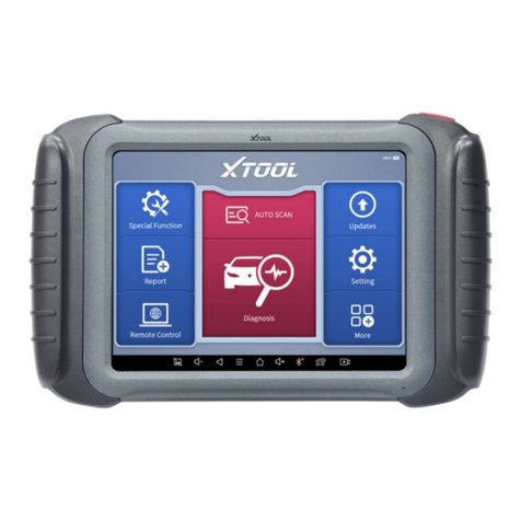
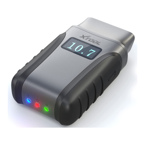
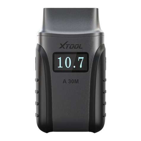
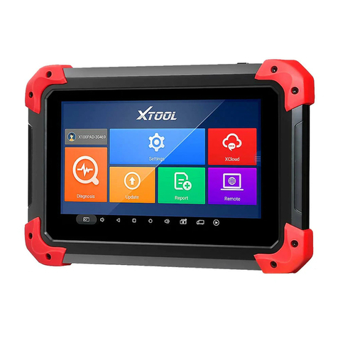
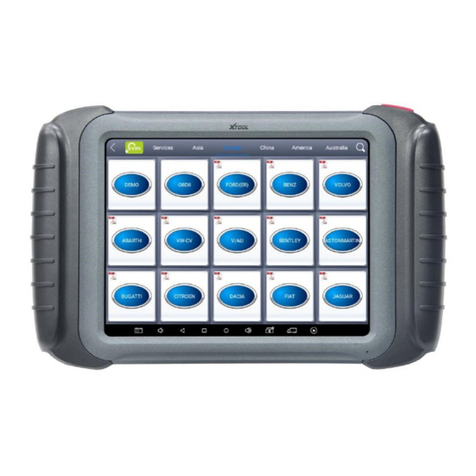
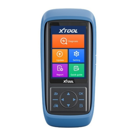
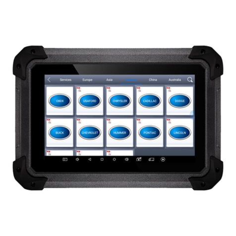
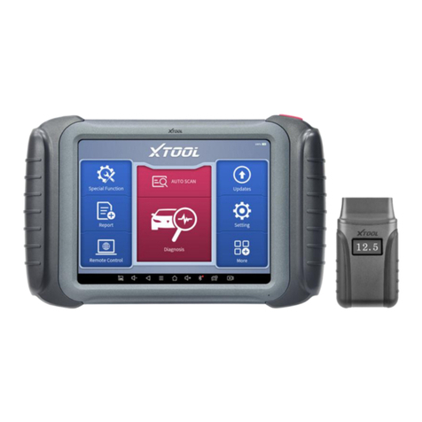
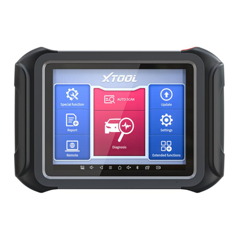
Xtool A80 User manual

A80 BT Intelligent Diagnosis System
1
A80 user manual
1. This manual is designed for the usage of A80, applying to A80 automotive
diagnosis platform.
No part of this manual can be reproduced, stored in a retrieval system or transmitted, in any
form or by any means (electronic, mechanical, photocopying, recording, or otherwise),
without the prior written permission of Xtool.
2. This electronic control system diagnostic unit is designed for professional vehicle
maintenance technicians. It has a certain reliability, however, it can not exclude vehicle
damage and loss caused by customer technical problems, vehicle problems or other factors, so
users need to take risks.
3. Use the device only as described in this manual. The user will be responsible solely for the
after-effects of violating the laws and regulations caused by using the product or its data
information, Xtool will not bear any legal responsibility for that.
4. Xtool shall not be liable for any incidental or consequential damages or for any economic
consequential damages arising from the accidents of individual users and the third parties,
misuse or abuse of the device, unauthorized change or repair of the device, or the failure
made by the user not to use the product according to the manual.
5. All information, specifications and illustrations in this manual are based on the latest
configurations and functions available at the time of printing. Xtool reserves the right to make
changes at any time without notice.
6. is the registered trademark of Shenzhen Xtooltech Co., Ltd.
7.In countries that the trademarks, service marks, domain names, logos and the name of the
company are not registered, Xtool claims that it still reserves the ownership of the
unregistered trademarks, service marks, domain names, logos and the company name. All
A80 BT Intelligent Diagnosis System
2
other marks for the other products and the company’s name mentioned in the manual still
belong to the original registered company. You may not use the trademarks, service marks,
domain names, logos and company name of Xtool or other companies mentioned without
written permission from the trademark holder.
8. Please visit http://www.xtooltech.com for more information about A80 BT.
9. Xtool reserves the right for the final interpretation of this manual content.
Contents
ChapterI About A80 BT ....................................................................................................................3
1. Appearance............................................................................................................................3
2. Layout of A80 BT Tablet ......................................................................................................5
2.1 Top View of A80 BT Tablet .....................................................................................5
2.2 Side View of A80 BT Tablet .......................................................................................5
2.3 Outline diagram of VCI diagnostic kit........................................................................6
2.4 A80 BT technical parameters ......................................................................................7
Chapter II How to use A80 BT .........................................................................................................8
1. A80 BT activation .................................................................................................................8
2. A80 BT main interface and function buttons description....................................................10
2.1 Main interface ...........................................................................................................10
2.2 Sub-menu and function buttons.................................................................................10
2.3 Toolbar functional buttons ........................................................................................13
3. Connection diagnosis ..........................................................................................................14
3.1 Vehicle Connection test.............................................................................................14
3.2 Precautions Before Use.............................................................................................15
4. Diagnosis.............................................................................................................................16
4.1 Menu selection:......................................................................................................17

A80 BT Intelligent Diagnosis System
3
4.2 Test function:..........................................................................................................18
4.3 Read ECU:.............................................................................................................21
4.4 Read DTCs:............................................................................................................22
4.5 Clear DTCs:...........................................................................................................23
4.6 Read live Data:..........................................................................................................24
4.7 Special function:.....................................................................................................25
4.8 Actuating components test:....................................................................................25
5. Setting: ................................................................................................................................26
6. Diagnose report...................................................................................................................30
6.1 Diagnose report:........................................................................................................30
6.2 Data playback............................................................................................................31
7. One-click upgrade:..............................................................................................................31
8. Xtool Cloud System ............................................................................................................32
9. Remote control:...................................................................................................................33
Chapter III Location of Diagnostic link connectors on Different vehicle Models..........................35
1. Diagnostic link connectors locations of various vehicle models: .......................................35
2. Location diagram of vehicle diagnostic link connectors:....................................................39
3. Diagnostic Link Connectors Terminal Definition and Communication Protocols..............40
Chapter IV Additional Information.................................................................................................43
1. Description of OBDII and the function of sensor components ...........................................43
1.1 OBDII function description.......................................................................................43
1.2 Sensor element function............................................................................................45
2. Common faults and elimination of electronic control system.............................................51
ChapterI About A80 BT
1. Appearance

A80 BT Intelligent Diagnosis System
4
1.1 Front view
1.2 Back view

A80 BT Intelligent Diagnosis System
5
2. Layout of A80 BT Tablet
2.1 Top View of A80 BT Tablet
①② ③ ④ ⑤
①USB3.0 interface: Wired data transmission
②Mini HDMI interface: Transmission of audio and video
③DB15 interface: Subsequent extended reservation port
④DC charging port: Charge for equipment, use 12V power supply
⑤Power Button: Power on or power off
2.2 Side View of A80 BT Tablet
①

A80 BT Intelligent Diagnosis System
6
①Seat adapter: This is reserved for the socket, and can be charged
with charging.
2.3 Outline diagram of VCI diagnostic kit
①Display: For voltage display
②OBD interface (head): Used to connect vehicles with international
standard OBDII diagnostic seats.
③Lighting switch: Press the button, the lighting will be on, that
convenient for users to find OBD diagnostic seat or other lighting.
④Bluetooth indicator: Bluetooth connection is successful, the
indicator is blue; Bluetooth is not connected, the indicator is not on.
⑤Power indicator: The light is red after the power is connected.
⑥Vehicle diagnostic light: Entering the diagnostic system shows a
green light flashing.
Function

A80 BT Intelligent Diagnosis System
7
VCI diagnostic box function: After inserting the vehicle diagnostic seat, it
connects with A80 BT host computer by Bluetooth to realize wireless
data transmission.
2.4 A80 BT technical parameters
Operating system: Android
Processor: quad core processor 1.8GHz
Memory: 2GRAM, 32GROM
Display / touch screen: 1024·768 resolution, 8 inch LED
Compatible touch screen
Camera: rear camera, 8 million pixels, with flash autofocus.
Sensor: gravity sensor
Audio input / output: microphone, 4 band 3.5 millimeter stereo.
Interface: USB3.0, DC charging port, MINI HDMI, DB15 interface.
Battery: 10000mAh 3.7V lithium polymer battery
Input voltage: +9~+36VDC, compatible with 12V and 24V voltage
system.
Working temperature: -20 to 50 C (-4 to 126 C)
Relative humidity: <90%

A80 BT Intelligent Diagnosis System
8
Appearance size: 275·183·33.9 (mm)
Chapter II How to use A80 BT
1. A80 BT activation
1.1 In order not to affect the using and upgrading of newly released
software, please be sure to activate A80 BT.

A80 BT Intelligent Diagnosis System
9
1.2 First turn on the A80 BT host, enter the tablet setting function to
enable the WLAN function, and connect to the wireless network. Click
the A80 BT Diagnostics icon to activate the page: 1. Enter the activation
code on the certificate; 2. Enter the six digits after the S/N code on the
certificate; 3. Enter a username, such as A repair shop; 4, please enter the
correct format of the mailbox account; 5 and 6, please enter a consistent
custom password in the two columns. After clicking the activation, you
will be prompted to verify the mobile number. Please enter the mobile
number, receive the SMS verification code, and enter the verification
code in A80 BT.
Note: In order to improve A80 BT, every time period, Xtool will update
A80 BT, pop up the update box directly on the diagnosis interface, click

A80 BT Intelligent Diagnosis System
10
to install.
2. A80 BT main interface and function buttons description
2.1 Main interface
After A80 BT boot, the main interface and sub menu are shown
below.▼
2.2 Sub-menu and function buttons

A80 BT Intelligent Diagnosis System
11
Functional Buttons
Functional descriptions
Diagnostic functions and special
functions enter the button, and then
select the desired functions for
operation, such as reading diagnostic
information, viewing data flow
parameters, performing motion tests,
special functions, etc.
During the diagnosis of the
vehicle, all diagnostic operations will
be recorded, the exit system will
prompt whether to save, the choice will
be saved in the diagnostic report, such
as vehicle information, system
information, diagnostic information,
test date, etc; enter the read data stream
function, click data stream playback,
the recorded dynamic data stream will
be saved in the data stream playback,
enter the diagnostic report, select the

A80 BT Intelligent Diagnosis System
12
corresponding date and model to view.
By selecting “Setting”, users can
access the language setting and other
system related settings.
Online communication cloud
Platform.
After the user activates, you can
upgrade the newly developed
diagnostic software by directly
clicking the one-click upgrade. The
software is continuously updated.
Please pay attention to the official
website upgrade announcement or
public announcement, and upgrade in
time.

A80 BT Intelligent Diagnosis System
13
This feature can accept Remote
Assistance from the Xtool company
Technical Support Center.
2.3 Toolbar functional buttons
Functional
Buttons
Descriptions
Return to previous interface
decrease volume
increase volume
Return to the main interface of Android system
Display recent usage procedures
Press this button for screen captures.
Click this button to return to the diagnostic vehicle
interface, and the Bluetooth connection light will be shown
in blue.

A80 BT Intelligent Diagnosis System
14
Click this button to return to the diagnostic vehicle
models interface.
3. Connection diagnosis
3.1 Vehicle Connection test
(1)The A80 BT host is connected to the vehicle through the VCI
diagnostic box with the main test line.
(2)Turn on the car ignition switch and press the A80 BT key to
diagnose the vehicle (see diagram below).

A80 BT Intelligent Diagnosis System
15
①A80 BT Mainframe
②VCI box (can be directly connected to the vehicle diagnostic
seat or select ③⑤ Accessory after connecting the vehicle diagnostic
seat)
③Adapter cable (optional for non-standard OBD II 16pin
connectors)
④Measured vehicle
⑤Adapter (optional for non-standard OBD II 16pin connectors)
3.2 Precautions Before Use
(1)Battery voltage range on the car: +9~+36VDC.
(2)When the test harness is unplugged, the application hand pinch the
head of the front end of the wire harness to unplug, do not pull the middle
segment of the wiring bundle, and the plug connection beam sees the
direction of the corresponding interface flat plug, and does not tend to be
inserted to avoid damaging the terminal.
(3)When carrying out some special functions tests, users are required to
operate the device according to operating instructions. For some tests the
vehicle has to meet certain requirements, for example: engine temperature
80℃/105℃, turn off loads (such as headlights, air-conditioner, etc.), put
accelerator pedal in released position, etc.

A80 BT Intelligent Diagnosis System
16
(4)As the domestic models equipped with the electronic control system
is messy, such as the failure to test or test data is not correct, consider the
selected menu and the measured electronic control system is appropriate,
you can find the vehicle ECU, through the ECU sticker model for menu
selection.
(5)You may not have a software upgrade or consult with the company's
technical services when you do not find the vehicle or electronic control
system in the A80 BT test menu.
(6)It is forbidden to use the wiring harness of the non-Xtool technology
company to test the connection to avoid unnecessary loss.
(7)In A80 BT and vehicle communication, the direct shutdown is
prohibited. You should cancel the task before returning to the main
interface for shutdown.
(8)The use of A80 BT should be lightly handled, as far as possible to
avoid vibration or impact. To ensure the service life of the touchscreen,
touch the screen gently.
(9) During long period of non-use, please disconnect the power and
then turn off the A80 BT unit.
4. Diagnosis

A80 BT Intelligent Diagnosis System
17
4.1 Menu selection:
(1)After the VCI box is connected to the car and the A80 BT
host is successfully paired with the wireless Bluetooth, the diagnostic
interface can be performed as shown in the following figure
(2)The menu can be selected according to your needs: Choose
European car to enter the European car system, choose Asian Car Show
Asian menu, choose the American Car into the American menu, choose
the domestic car into the domestic menu, according to the model of the
diagnosis of the choice of car system to enter the search. You can
quickly search by clicking on the magnifying glass icon in the top right
corner and entering models.

A80 BT Intelligent Diagnosis System
18
(3)In addition to common system troubleshooting, the
development team also develops a range of special diagnostic functions
for some vehicles, as follows.
4.2 Test function:
(1)Using "BMW car" as an example, select "Royal Car V8.70",
and then select the "GX9" menu to enter, you can see the "Engine
system" icon, find the UMC engine system (UDS), click into the
following image:

A80 BT Intelligent Diagnosis System
19
The main function menu for different cars is slightly different, and the
following options are included in the common main features menu:
Read version information: This function reads the ECU version
information and displays it as “system identification” or “system
information” menu in some electronic control. It has the same meaning,
and reads the software and hardware versions related to the ECU, the
model of the diesel engine, Information such as the date of manufacture
and part number. It is convenient for us to make records during the
maintenance process, and also facilitate future data feedback and data
management.

A80 BT Intelligent Diagnosis System
20
Read ECU: read the current fault code in the ECU.
Read DTCs: Read the fault codes of the history store in the ECU.
Clear DTCs: Clear the current and historical fault code memory
stored in the ECU. It can be cleared only after all faults have been
eliminated. If there is a fault that is not eliminated, the fault code cannot
be successfully cleared. The fault code is always stored in the ECU and
read this fault code ever. Recommendation: Do not remove the fault code
casually. After reading the fault code, we must first record the fault
content for the maintenance reference. When the fault is processed, there
will be no fault code after re-reading the fault code.
Read live data: It is to read the parameters of the current engine
running, such as oil pressure, temperature, engine speed, fuel temperature,
coolant temperature, intake air temperature and so on. Through these
parameters, we can basically directly determine which problems have
occurred, so that we have narrowed the scope when performing
maintenance, which is more convenient. For many vehicles in the actual
operation process, because of the deviation of the operating
characteristics of the electronic components, the sensitivity reduction,
which all can be judged in the data stream; For this function, we need to
be very familiar with the parameters of the engine, such as: idle speed
For 800RPM or 750RPM, when the operating temperature of the coolant
Table of contents
Other Xtool Diagnostic Equipment manuals