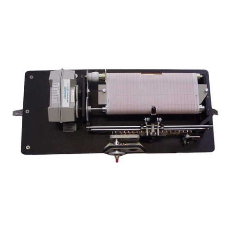
Dickson KT6P1 Operating and maintenance instructions

Dickson KT6P Manual V3
1
DICK
DICKDICK
DICKSON
SON SON
SON
KT6P1 / KT6P2 / KT6P5
KT6P1 / KT6P2 / KT6P5KT6P1 / KT6P2 / KT6P5
KT6P1 / KT6P2 / KT6P5
Remote Sensing
Remote SensingRemote Sensing
Remote Sensing
Temperature
TemperatureTemperature
Temperature
Recorder
RecorderRecorder
Recorder
G TTING START D
G TTING START DG TTING START D
G TTING START D
7-day chart rotation
0 to 100
o
F
QUICK START
QUICK STARTQUICK START
QUICK START
1.
1.1.
1. Remove the protective pen cap.
2.
2.2.
2. Connect Probe: Make sure the KTC probe is connected firmly to the Replaceable Sensor
and that the Replaceable Sensor is plugged in firmly to the chart recorder.
3.
3.3.
3. Insert 4AA batteries and plug in AC adapter (See Figure 3). Unit will power on.
4.
4.4.
4. The instrument will move pen to the appropriate readings.
5.
5.5.
5. Install the chart that matches the Dip Switch settings (See p.4).
Press the P N
P NP N
P N
HOM
HOMHOM
HOM key to move the pen to the outside of the chart. The pen is
automatically raised off the chart.
Remove the old chart, place the new chart on the Chart Hub being certain that the edge
of the chart slides under the Chart Guide Clip located at the outside of the chart.
6.
6.6.
6. Set the appropriate time. There are two ways to adjust the chart and set the appropriate
time:
a. Set the chart time manually by inserting a coin into the groove in the chart hub
and turning clockwise until the correct hour (and day if applicable) on the chart
is referenced to the timing arrow (just to the right of the pen tip on the dial).
Press Pen
PenPen
Pen
Home
HomeHome
Home to move the pen(s) back onto the chart.
The following feature should be used for fine adjustments only.
b. To adjust the chart time, press and hold Adjust
AdjustAdjust
Adjust-
--
-Up
UpUp
Up and Adjust
AdjustAdjust
Adjust-
--
-Down
DownDown
Down buttons
located on the back of the unit next to the dip switch (see Figure 3).
The green L D will blink rapidly for about five seconds, then the L D will remain
solid green. While in this state the Adjust
AdjustAdjust
Adjust-
--
-Up
UpUp
Up button will move the chart
backward (counter clockwise) and the Adjust
AdjustAdjust
Adjust-
--
-Down
DownDown
Down button will move the chart
forward (clockwise).

Dickson KT6P Manual V3
2
Rotate the chart until the correct hour (and day if applicable) on the chart is
referenced to the timing arrow. Once you have set your chart, press the Pen
Pen Pen
Pen
Home
Home Home
Home button to exit Chart Adjust Mode. The unit will take one minute to exit
the Chart Adjust Mode once Pen
PenPen
Pen
Home
HomeHome
Home is pressed. Press Pen
PenPen
Pen
Home
HomeHome
Home to move the
pen(s) back onto the chart.
c. Place the KT6 recorder on a flat vibration-free surface. Be sure it is in a vertical
position and level. For best performance and longevity, the location should be a
clean environment, free from dust and corrosive fumes. Do not exceed
temperature specifications. Wall Mount:
Wall Mount:Wall Mount:
Wall Mount: Keyhole slots are provided on the KT6
recorder for wall mounting.
DISPLAY SYMBOLS
DISPLAY SYMBOLS DISPLAY SYMBOLS
DISPLAY SYMBOLS KT6
KT6KT6
KT6
Figure 1
Figure 1Figure 1
Figure 1
Figure 2
Figure 2Figure 2
Figure 2
Figure 3
Figure 3Figure 3
Figure 3

Dickson KT6P Manual V3
3
Keypad and Button Functions
Keypad and Button FunctionsKeypad and Button Functions
Keypad and Button Functions
On/Off
On/OffOn/Off
On/Off
The On/Off key turns the unit on and off.
Pen
PenPen
Pen
Home
HomeHome
Home
If the pen is located on the outside edge of the chart, press Pen
PenPen
Pen
Home
HomeHome
Home to move pen to recording
position. If the pen is located on the chart, press Pen
PenPen
Pen
Home
HomeHome
Home to move the pen to the outside
edge of the chart.
A
AA
Alarm
larm larm
larm (
((
(KT6P5)
KT6P5)KT6P5)
KT6P5)
1.
1.1.
1. To set the alarm, make sure unit is on and press and hold the Alarm
AlarmAlarm
Alarm button. The L D will
blink red rapidly for about five seconds, then the L D will turn solid green. Release the
Alarm
AlarmAlarm
Alarm button and the L D will turn solid red. At this point the display will show “On” or “Off”.
Pressing either the Adjust
AdjustAdjust
Adjust-
--
-Up
UpUp
Up or Adjust
AdjustAdjust
Adjust-
--
-Down
DownDown
Down buttons, located on the back of the unit next
to the dip switch, will toggle the alarm on or off.
2.
2.2.
2. Pressing P N
P NP N
P N
HOM
HOMHOM
HOM will scroll to the next alarm option. The options are as follows:
Alarm on or off
Pen 1 alarm minimum
Pen 1 alarm maximum
3.
3.3.
3. In order to set pen alarm minimum and maximum, pressing Adjust
AdjustAdjust
Adjust-
--
-Up
UpUp
Up will increase the
alarm value, and pressing Adjust
AdjustAdjust
Adjust-
--
-Dow
DowDow
Down
nn
n will decrease the alarm value. There is acceleration
if the Adjust
AdjustAdjust
Adjust-
--
-Up
UpUp
Up button is held down.
Repetitively pressing the Pen
PenPen
Pen
Home
HomeHome
Home button will scroll through the three options until the
A
AA
Alarm
larmlarm
larm button is pressed to exit from alarm adjust. ach press of the Pe
PePe
Pen
nn
n
Home
HomeHome
Home or Alarm
AlarmAlarm
Alarm
button will store the new settings. The unit will take one minute to exit Alarm Set Mode
once the Alarm
AlarmAlarm
Alarm button is pressed.
4.
4.4.
4. If the alarm is triggered, the L D will show as solid red and the alarm will sound. Press the
Alarm
AlarmAlarm
Alarm button to silence the audible alarm.
Alarm Relays
Alarm RelaysAlarm Relays
Alarm Relays
(KT6P5)
(KT6P5)(KT6P5)
(KT6P5)
The SPST 24V 500mA relay contacts are normally open and will close on alarm conditions when
the alarms are enabled. Relay contacts are always functional when the alarm is enabled. The
relay will close only during minimum and maximum alarm conditions. Relays will not operate
under battery only power conditions

Dickson KT6P Manual V3
4
DIP SWITCH S TUP
DIP SWITCH S TUPDIP SWITCH S TUP
DIP SWITCH S TUP
To setup the KT6 recorder for your specific application, you might need to change some of
the Dip Switches. The Dip Switches are located on the back of the unit. (Figure 3)
Use a pen or small screw driver to flip the switches. Remember to install the correct chart
to match the corresponding Dip Switch setting.
Recording Time
Recording TimeRecording Time
Recording Time:
: :
: The KT6 recorder has two different recording time options
7 Day
7 Day7 Day
7 Day
#2 Down
#2 Down#2 Down
#2 Down
24 Hour
24 Hour24 Hour
24 Hour
#2 Up
#2 Up#2 Up
#2 Up
F/C
F/CF/C
F/C:
: :
: Record in degrees F or C
F
FF
F
#3 Down
#3 Down#3 Down
#3 Down
C
CC
C
#3 Up
#3 Up#3 Up
#3 Up
Temperature Ran
Temperature RanTemperature Ran
Temperature Range
gege
ge:
: :
: Select the temperature ranges that matches the chart paper
0 to +100 F/C
0 to +100 F/C0 to +100 F/C
0 to +100 F/C
#4 Down
#4 Down#4 Down
#4 Down
#5 Down
#5 Down#5 Down
#5 Down
#6 Down
#6 Down#6 Down
#6 Down
-
--
-50 to 0 F/C
50 to 0 F/C50 to 0 F/C
50 to 0 F/C
#4 Down
#4 Down#4 Down
#4 Down
#5 Down
#5 Down#5 Down
#5 Down
#6 Up
#6 Up#6 Up
#6 Up
-
--
-100 to 0 F
100 to 0 F100 to 0 F
100 to 0 F
#4 Down
#4 Down#4 Down
#4 Down
#5 Up
#5 Up#5 Up
#5 Up
#6 Up
#6 Up#6 Up
#6 Up
-
--
-50 to 50 F/C
50 to 50 F/C50 to 50 F/C
50 to 50 F/C
#4 Up
#4 Up#4 Up
#4 Up
#5 Down
#5 Down#5 Down
#5 Down
#6 Down
#6 Down#6 Down
#6 Down
0 to 50 F/C
0 to 50 F/C0 to 50 F/C
0 to 50 F/C
#4 Down
#4 Down#4 Down
#4 Down
#5 Up
#5 Up#5 Up
#5 Up
#6 Down
#6 Down#6 Down
#6 Down
+50 to 100
+50 to 100 +50 to 100
+50 to 100 F/C
F/CF/C
F/C
#4 Up
#4 Up#4 Up
#4 Up
#5 Up
#5 Up#5 Up
#5 Up
#6 Up
#6 Up#6 Up
#6 Up
0 to 500 F/C
0 to 500 F/C0 to 500 F/C
0 to 500 F/C
#4 Up
#4 Up#4 Up
#4 Up
#5 Up
#5 Up#5 Up
#5 Up
#6 Down
#6 Down#6 Down
#6 Down
0 to 250 F/C
0 to 250 F/C0 to 250 F/C
0 to 250 F/C
#4 Up
#4 Up#4 Up
#4 Up
#5 Down
#5 Down#5 Down
#5 Down
#6 Up
#6 Up#6 Up
#6 Up

Dickson KT6P Manual V3
5
POW R
POW RPOW R
POW R
The KT6 operates on AC power with an optional 4AA battery backup. Depending on
chart rotation selected and model; battery backup will last approximately 3 days.
Note: Alarm and relays will not operate under battery only power.
L D Indicators
L D IndicatorsL D Indicators
L D Indicators
• AC Power with Battery Backup - Solid Green
• AC Power with Low Battery or No Battery - Blinks Red
• Battery Only - Blinks Green
• Battery Only (Low Battery) - Solid Red
P N HOM ADJUST
P N HOM ADJUSTP N HOM ADJUST
P N HOM ADJUST
If over time the pen location does not match the display, you may need to adjust the pen
location on the chart. A Pen Home Adjustment will not affect calibration of the sensor,
but rather corrects for the natural drift that occurs with mechanical moving parts over
time.
1. While the unit is on, press and hold both Pen Home
Pen HomePen Home
Pen Home and On/Off
On/OffOn/Off
On/Off
buttons until the
L D is solid green. Release the Pen Home
Pen HomePen Home
Pen Home and On/Off
On/OffOn/Off
On/Off buttons. The L D will
flash amber and green for one second then the L D will turn off.
Note:
Note:Note:
Note: Press Pen Home
Pen HomePen Home
Pen Home first so the unit will not turn off
2. The pen will move to the outer edge of the chart, and then the red
redred
red pen will move
to the outer chart ring (maximum temperature line).
3. If the red pen tip does not line up with the outer chart ring, use the Adjust
AdjustAdjust
Adjust-
--
-Up
UpUp
Up
and Adjust
AdjustAdjust
Adjust-
--
-
Down
DownDown
Down buttons (on the back of the unit) to move the red pen so that
the pen tip is on top of the outer chart ring.
4. Once set press On/Off
On/OffOn/Off
On/Off to save and exit Pen Home Adjust.
Note: Pressing the On/Off button will exit the adjustment and return the unit to normal
operation. ach time the Pen Home or On/Off button is pressed, the adjustment
currently in progress will be stored. The unit will take one minute to exit Pen Adjust
Mode once the On/Off button is pressed.

Dickson KT6P Manual V3
6
CALIBR
CALIBRCALIBR
CALIBRATION
ATIONATION
ATION
The R400 Replaceable Sensor was carefully tested and calibrated before being
shipped from the factory. For greatest accuracy, we recommend replacing the
sensor every 6-12 months.
To order a Calibrated Replacement Sensor Call customer service at (630) 543-
3747 or go to www.dicksondata.com.
When your new Replaceable Sensor arrives, simply turn off the recorder, remove
and discard the old sensor, plug in the new one and power the recorder back on.
Your recorder will continue to record temperature and humidity without
interruption.
US R CALIBRATION
US R CALIBRATIONUS R CALIBRATION
US R CALIBRATION
If you have an accurate standard to compare against, the Replaceable Sensor calibration
can be adjusted at one point. This will not adjust the span and is not as accurate as
replacing the Replaceable Sensor with a newly calibrated one.
1. To activate Calibration mode, turn the unit on and press and hold both the On/Off
On/OffOn/Off
On/Off
and the Adjust
AdjustAdjust
Adjust-
--
-Down
DownDown
Down button until the L D is solid green. The L D will then blink
amber and at which point only the pen being adjusted will show on the display.
Note:
Note:Note:
Note:
Make sure to press the Adjust-Down button first so the unit will not turn off
2. To raise the unit of measurement, press the Adjust
AdjustAdjust
Adjust-
--
-Down
DownDown
Down button. To lower the unit
of measurement, press the Adjust
AdjustAdjust
Adjust-
--
-Up
UpUp
Up button.
3. When Calibration is complete, press the On/Off
On/OffOn/Off
On/Off button. The adjustment is stored in
memory even after you turn the unit off or if AC power fails.
Note:
Note:Note:
Note: After two hours, if no buttons are pressed, the unit will time out of Calibration
mode and resume normal operation. If you wish to cancel the Calibration, simply
enter Calibration mode and toggle through the steps without adjusting displayed
readings. xit by pressing the On/Off
On/OffOn/Off
On/Off button. You have now restored factory
calibration settings.
Note:
Note: Note:
Note: It is recommended that you use a controlled chamber when determining if
Calibration is necessary. Adjusting the pen in an open room is not recommended as
air flow can vary greatly within a very small area.

Dickson KT6P Manual V3
7
TROUBL SHOOTING
TROUBL SHOOTINGTROUBL SHOOTING
TROUBL SHOOTING
Why isn't the chart keeping time or running slow?
Why isn't the chart keeping time or running slow?Why isn't the chart keeping time or running slow?
Why isn't the chart keeping time or running slow?
•The chart may be hung up or restricted, possibly caused by a rip on the outer
edge of the chart or the chart hub, or the chart may be caught between the arm
and pen(s) arm platform.
•Incorrect chart installed for the selected chart speed.
Why did the chart stop turn
Why did the chart stop turnWhy did the chart stop turn
Why did the chart stop turning?
ing?ing?
ing?
•Chart hung up or restricted, (ripped chart)
•Unit may be "locked up", this can be confirmed by pressing any of the buttons on
the keypad, if the unit is locked up there will be no response to button presses
and the Chart Recorder may appear to be working, but the readings won't
change, also the chart will not rotate. Remove power and battery, and then re-
power.
Why don't the display and chart match?
Why don't the display and chart match?Why don't the display and chart match?
Why don't the display and chart match?
•Dip switches set for a specific range, but using chart for another range, or vice
versa.
•Pen(s) not inserted on pen arm(s) all the way
•To adjust pen(s) to match chart see “Pen Home Adjust” in the “Need to Know”
section of this manual.
Why does the display read PROB?
Why does the display read PROB?Why does the display read PROB?
Why does the display read PROB?
•Check the sensor pod and KTC probe(s). Make sure it is properly plugged into
the unit.
•Is the unit locked up? This can be confirmed by pressing any of the buttons on
the keypad, if the unit is locked up there will be no response to button presses
and the unit may appear to be working, but the readings won't change, also the
chart will not rotate. Remove power and battery, and then re-power.
Why does calibration seem to be off?
Why does calibration seem to be off?Why does calibration seem to be off?
Why does calibration seem to be off?
•What is the tolerance of the unit it's being compared to?
•It's ok if the unit is within the sum of the two tolerances.
•Has an outside calibration house attempted calibration? It may not have been
adjusted properly.
•Walk through calibration adjustment, found in the manual
Why won't the battery back
Why won't the battery backWhy won't the battery back
Why won't the battery back-
--
-up work?
up work?up work?
up work?
•Are there good batteries in the Chart Recorder?
•Keep in mind that battery backup varies significantly depending on temperature,
pen movement and chart rotation speed.

Dickson KT6P Manual V3
8
•If there was a momentary power outage (Brown out), the unit may not have had
enough time to recognize this and switch to battery mode. (The Chart Recorder
may lock up or shut off in this situation) This situation may also occur if the unit
is plugged into an outlet that shares the circuit with other machinery that has
phase motors or compressors that cycle periodically. As these other machines
cycle, they momentarily have a high current draw, therefore drawing from the
unit.
Why won't the chart recorder respond to changes?
Why won't the chart recorder respond to changes?Why won't the chart recorder respond to changes?
Why won't the chart recorder respond to changes?
•Is the unit locked up? This can be confirmed by pressing any of the buttons on
the keypad, if the unit is locked up there will be no response to button presses
and the unit may appear to be working, but the readings won't change, also the
chart will not rotate. Remove power and batteries, and then re-power.
Why won't the unit power up?
Why won't the unit power up?Why won't the unit power up?
Why won't the unit power up?
•Remove the batteries and power adapter for a minute or two, this will reset the
unit. The unit should respond when the adapter is plugged in.
WARRANTY
WARRANTYWARRANTY
WARRANTY
Dickson warrants that this line of instruments will be free from defects in material and
workmanship under normal use and service for a period of twelve months after delivery.
This warranty does not cover routine calibration and battery replacement.
For Specifications and Technical Support go to www.DicksonData.com
FACTORY S RVIC AND R TURNS
FACTORY S RVIC AND R TURNSFACTORY S RVIC AND R TURNS
FACTORY S RVIC AND R TURNS
Contact Customer Service (630.543.3747) for a Return Authorization (RA) Number
before returning any instrument. Please have the model number, serial number and a
PO number ready before calling.

Dickson KT6P Manual V3
9
Replaceable Sensor Certificate of Validation
Replaceable Sensor Certificate of ValidationReplaceable Sensor Certificate of Validation
Replaceable Sensor Certificate of Validation
Dickson ensures that the Replaceable Sensors / Instruments listed below were
developed, tested and validated together.
Replaceable Sensor Model: R400
Instrument Model: KT6P1, KT6P2, KT6P5
Operation
OperationOperation
Operation: The Instruments and Replaceable Sensor models listed above were
specifically designed to work together. No other sensors will work with the Instrument
models listed. No other Instrument will work with the Replaceable Sensors listed. The
Replaceable Sensor must be connected to the Instrument for the Instrument to operate
properly.
Calibration
CalibrationCalibration
Calibration: Only the Replaceable Sensor is calibrated. The sensor, and all calibration
defaults and adjustments are stored on the Replaceable Sensor. Accuracy is strictly
controlled by the sensor – no adjustments are made by the Instrument. Readings are
sent from the Replaceable Sensor to the Instrument for storage purposes only.
Certificates of Calibration / NISTs are only supplied for the Replaceable Sensor for this
reason.
Recalibration
RecalibrationRecalibration
Recalibration: When a Replaceable Sensor is due for recalibration the existing
Replaceable Sensor can be replaced with a new Replaceable Sensor thus eliminating the
need to return the entire instrument for recalibration. Replaceable Sensors can be
returned for recalibration as well.
Other manuals for KT6P1
1
This manual suits for next models
2
Table of contents
Other Dickson Voice Recorder manuals

Dickson
Dickson THDx User manual
Dickson
Dickson PW4 User manual
Dickson
Dickson KT6 User manual
Dickson
Dickson VFC70 User manual
Dickson
Dickson VFC70 User manual

Dickson
Dickson ET6 User manual

Dickson
Dickson KT6P1 User manual

Dickson
Dickson KT6 User manual

Dickson
Dickson SL4 User manual
Dickson
Dickson TH6P1 User manual
