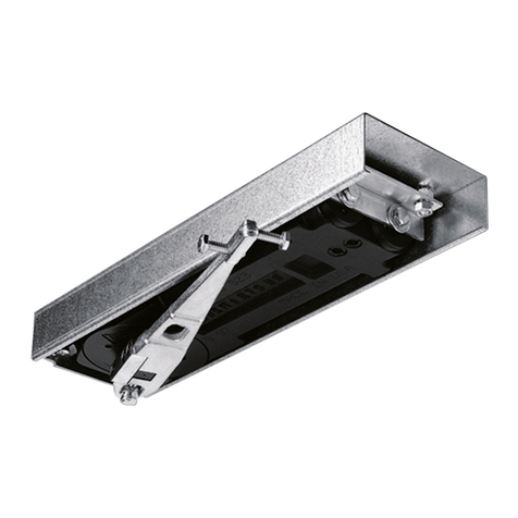
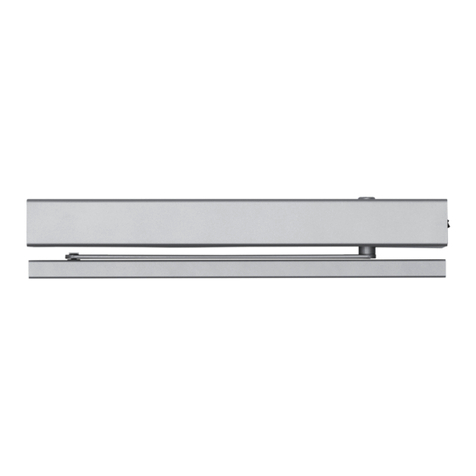
Dictator DICTAMAT SPR User manual

Technical Manual
DICTAMAT SPR
© DICTATOR Technik GmbH • Gutenbergstr. 9 • 86356 Neusäß • Germany
Tel. +49(0)821-24673-0 • Fax +49(0)821-24673-90 • E-mail info@dictator.de • 20210315 Page 04.051.1
Technical Manual
DICTAMAT SPR
You can find the current version of our manual on our website under «Downloads»:
https://en.dictator.de/products/door-drives-gate-drives/operators-hinged-doors/

Technical Manual
DICTAMAT SPR
© DICTATOR Technik GmbH • Gutenbergstr. 9 • 86356 Neusäß • Germany
Tel. +49(0)821-24673-0 • Fax +49(0)821-24673-90 • E-mail info@dictator.de • 20210315
Page 04.051.2
Table of Contents
I. General Safety Instructions 3
I. General Safety Instructions - cont. 4
II. Machinery Directive 5
III. Technical Data 6
III. Technical Data - cont. 7
3.1 Operating Instructions 7
3.2 Dimensions 7
IV. Installation Example 8
V. Main Components 9
VI. Mechanical Installation 10
6.1 Removing the housing 10
VII. Installation with SBS Sliding Arm 11
VIII. Installation with the Articulated Arm SBA 12
IX. Installation with the Three-part Articulated Arm
SPRBRAS 13
X. Installing the Final Stop on the Floor 14
XI. Electrical Connections 15
11.1 Electrical Connections for 230 V~ / 120 V~ Power Supply 15
XI. Electrical Connections - cont. 16
11.2 Electrical Connections for 24 V power supply 16
XII. Connecting the Power Supply 17
XIII. Commands/Switches 18
13.1 Testable Safety Devices 18
XIV. Outputs and Accessories 19
XIV. Outputs and Accessories - cont. 20
14.1 Operating Mode Selector Switch 20
XIV. Outputs and Accessories - cont. 21
XV. Electromagnetic Emissions 22
XVI. Adjustments 23
16.1 Activation Procedure 23
16.2 DIP Switches 23
XVI. Adjustments - cont. 24
XVI. Adjustments - cont. 25
16.3 Trimmers 25
16.4 Signals 25
XVII. Requirements for Doors for Use in Low Energy Mode 26
XVIII. Commissioning 27
XVIII. Commissioning - cont. 28
XIX. Troubleshooting 29
XIX. Troubleshooting - cont. 30
XX. Regular Maintenance Plan 31
XXI. Installation Example with Operation Selector Switch 32

Technical Manual
DICTAMAT SPR
© DICTATOR Technik GmbH • Gutenbergstr. 9 • 86356 Neusäß • Germany
Tel. +49(0)821-24673-0 • Fax +49(0)821-24673-90 • E-mail info@dictator.de • 20210315 Page 04.051.3
Failure to comply with the information contained in this manual may
result in injury or damage to the unit.
Keep this manual for future reference!
This installation manual is intended for qualified personnel only.
The installation, electrical connection and adjustment work must be car-
ried out in accordance with the manual and in compliance with all
relevant standards and regulations.
Read the instructions carefully before installing the product. Incorrect
assembly can lead to injuries and property damage.
The packaging materials (plastic, polystyrene, etc.) must be disposed of
properly and must not get into children‘s hands as they are a potential
source of danger.
Before installing the product, make sure it is in perfect condition.
Do not install the product in explosive areas and atmospheres: the pre-
sence of inflammable gas or fumes represents a serious safety hazard.
Before mounting the drive, make any necessary structural changes to
ensure that safety clearances are maintained and that any pinch, shear,
movement or general hazard areas are safeguarded or isolated.
Check that the existing structure meets the requirements for strength and
stability. The manufacturer of the unit is not responsible for the lack of
stability of the technical construction of the doors where the units are to
be installed, nor for any deformations that may occur when using the
units.
When installing and setting the safety devices (light barriers, contact
edges, emergency stops, etc.), be sure to observe the applicable stand-
ards and directives, the criteria of the technical rules of conduct, the in-
stallation environment, the operating logic of the system and the forces
developed by the motorised door.
The safety devices serve to protect against crushing, shearing, retrac-
tion and other danger areas of the motorised door.
The prescribed information signs must be provided to identify the dan-
ger areas.
For each installation, the characteristic data of the motorised door must
be attached in a visible place.
If necessary, connect the automated door to an effective earthing sys-
tem that complies with safety standards.
During installation, maintenance or repair work, disconnect the power
supply before opening the cover to access the electrical equipment.
The protective housing of the operator must only be removed by quali-
fied personnel.
I. General Safety Instructions

Technical Manual
DICTAMAT SPR
© DICTATOR Technik GmbH • Gutenbergstr. 9 • 86356 Neusäß • Germany
Tel. +49(0)821-24673-0 • Fax +49(0)821-24673-90 • E-mail info@dictator.de • 20210315
Page 04.051.4
Interventions on the electronic devices may only be carried out with an-
tistatic earthed arm protection. The manufacturer of the drive declines
all liability for the installation of components that are unsuitable in terms
of safety and operation.
Only original spare parts may be used when repairing or replacing the
products.
The fitter is obliged to provide the operator of the system with all neces-
sary information on the automatic, manual and emergency operation of
the motorised door and to hand over the operating instructions.
I. General Safety Instructions - cont.

Technical Manual
DICTAMAT SPR
© DICTATOR Technik GmbH • Gutenbergstr. 9 • 86356 Neusäß • Germany
Tel. +49(0)821-24673-0 • Fax +49(0)821-24673-90 • E-mail info@dictator.de • 20210315 Page 04.051.5
II. Machinery Directive
According to the Machinery Directive (2006/42/EC), the installer
who motorises a door or gate is subject to the same obligations as a
machine manufacturer and therefore has to do the following:
• Preparation of the technical file, which must contain the documents
referred to in Annex V of the Machinery Directive; (The technical
file must be kept and made available to the national authorities for
at least ten years. This period starts from the date of manufacture of
the motorised door.)
• Drawing up the EC Declaration of Conformity according to Annex
II-A of the Machinery Directive and handing it over to the customer;
• Affixing the EC marking to the motorised door in accordance with
point 1.7.3. of Annex I of the Machinery Directive.

Technical Manual
DICTAMAT SPR
© DICTATOR Technik GmbH • Gutenbergstr. 9 • 86356 Neusäß • Germany
Tel. +49(0)821-24673-0 • Fax +49(0)821-24673-90 • E-mail info@dictator.de • 20210315
Page 04.051.6
Türbreite [m
]
Türgewicht
[kg]
VM Anpassungen
Türgewicht [kg
]
7
6
5
4
3
2
1
120
100
80
60
40
20
SBA
SB S
0 10 20 30 40 50 60 70 80 90 100 110
0,7 0,8 0,9 1,0 1,1 1,2
III. Technical Data
SPR PN - P - V - INOX SPR L - L INOX
Power supply 230 VAC / 50/60Hz 24 VDC (requires pro-
tection by external fuse)
Power consumption 0.5 A 3 A
Rating 120 W 120 W
Torque 25 Nm 25 Nm
Insulation class class 2 /
Opening time min 3 s / 90°
max 6 s / 90°
min 3 s / 90°
max 6 s / 90°
Closing time min 4 s / 90°
max 7 s / 90°
min 4 s / 90°
max 7 s / 90°
Service class 5 - VERY INTENSE 5 - VERY INTENSE
Duty cycle S3 = 80% S3 = 80%
Type of operation Opening and closing
by motor
Opening and closing
by motor
Max load
(door leaf 0.9 m) 110 kg 110 kg
Max load
(door leaf 1.2 m) 70 kg 70 kg
Temperature min -20°C max +55°C min -20°C max +55°C
Temperature
with batteries min -10°C max +50°C min -10°C max + 50°C
IP rating IP30 IP30
Electronic control system EL38 EL38
Power pack AL05 /
F1 fuse F1A /
Motor output 24 V / 3.5 A 24 V / 3.5 A
Power supply of the
accessories 24 V / 0.3 A 24 V / 0.3 A
Door weight [kg]
Door width [m] Door weight [kg]
VM adjustment

Technical Manual
DICTAMAT SPR
© DICTATOR Technik GmbH • Gutenbergstr. 9 • 86356 Neusäß • Germany
Tel. +49(0)821-24673-0 • Fax +49(0)821-24673-90 • E-mail info@dictator.de • 20210315 Page 04.051.7
3.1 Operating
Instructions
III. Technical Data - cont.
Service class: 5 (minimum 5-year working life with 600 cycles per day).
Applications: VERY INTENSE (for entrances with very intense pedestrian
use).
• The performance characteristics refer to the recommended weight
(approx. 2/3 of the maximum permitted weight). When used with
the maximum permitted weight, a reduction in the above mentioned
performance levels can be expected.
• The service class, running times and number of consecutive cycles
are merely indicative, having been statistically determined under
average operating conditions and therefore not necessarily appli-
cable to specific conditions of use.
• Every automatic door has variable factors, such as: Friction, com-
pensation processes as well as environmental conditions can fun-
damentally change both the life and the quality of operation of
the door drive or part of its components (such as the automatic
systems). It is up to the installer to provide appropriate safety coef-
ficients for each situation.
3.2 Dimensions

Technical Manual
DICTAMAT SPR
© DICTATOR Technik GmbH • Gutenbergstr. 9 • 86356 Neusäß • Germany
Tel. +49(0)821-24673-0 • Fax +49(0)821-24673-90 • E-mail info@dictator.de • 20210315
Page 04.051.8
5
1
2
6
A
7 6
4
3
IV. Installation Example
Ref. Code Description
1SPR Door drive
2SBA
SBS
SPRBRAS
FBA
Articulated arm
Sliding arm
Three-part articulated arm
End stop for articulated arm
3Optional End stop on the floor
4Optional Function selector switch
5Optional Battery kit
6Optional Opening sensor
ATTENTION TO THE FIXING POSITION
7Optional Sensor for safe opening and closing
AConnect the power supply to a type-approved om-
nipolar switch, with a contact opening distance of
at least 3 mm (not supplied).
Connection to the mains must be via an indepen-
dent channel, separate from the connections to
the control and safety devices.

Technical Manual
DICTAMAT SPR
© DICTATOR Technik GmbH • Gutenbergstr. 9 • 86356 Neusäß • Germany
Tel. +49(0)821-24673-0 • Fax +49(0)821-24673-90 • E-mail info@dictator.de • 20210315 Page 04.051.9
V. Main Components
Ref. Code Description
124 V motor with encoder
2EL38 Electronic control system
3SPRBAT Battery kit
4Base plate
5ON/OFF button
6Function selector switch
7Arm support
8Stainless steel housing [SPR V - SPR LV - SPR VJ]

Technical Manual
DICTAMAT SPR
© DICTATOR Technik GmbH • Gutenbergstr. 9 • 86356 Neusäß • Germany
Tel. +49(0)821-24673-0 • Fax +49(0)821-24673-90 • E-mail info@dictator.de • 20210315
Page 04.051.10
VI. Mechanical Installation
Check the stability and weight of the door wing. Make sure it moves
smoothly, without any friction (reinforce the frame if necessary).
Any existing door closers must be removed or, alternatively, completely
deactivated.
ATTENTION
When installing on doors that separate areas with
different pressure levels, check that they function
properly.
6.1 Removing the
housing

Technical Manual
DICTAMAT SPR
© DICTATOR Technik GmbH • Gutenbergstr. 9 • 86356 Neusäß • Germany
Tel. +49(0)821-24673-0 • Fax +49(0)821-24673-90 • E-mail info@dictator.de • 20210315 Page 04.051.11
29 34
x8
D
500
min
650
150 max. 45
OPENING
F
G
B A
C
E
F
P
VII. Installation with SBS Sliding Arm
Use the SBS sliding arm for doors that open inwards (as seen from the
operator side).
• Remove the housing and fix the drive to the wall at the points indica-
ted (P) so that it is stable and horizontal, respecting the dimensions
indicated in the figure: refer to the axis of the hinges.
• Drill the guide [A] and fix it to the door.
• Insert the sliding block [B] of the sliding arm in the guide [A]. Fix
the arm [C] to the operator, making sure it is inserted in the arm
support seat [D].
• Position the cover [E] and the two heads [F].
• Adjust the internal end stop [G] in the best position

Technical Manual
DICTAMAT SPR
© DICTATOR Technik GmbH • Gutenbergstr. 9 • 86356 Neusäß • Germany
Tel. +49(0)821-24673-0 • Fax +49(0)821-24673-90 • E-mail info@dictator.de • 20210315
Page 04.051.12
min 10°
P x8
B
C
46
320
min 550
max 300
OPENING
max 30
44
VIII. Installation with the Articulated Arm SBA
Use the articulated arm SBA for doors that open outwards (as seen from
the operator side).
• Remove the housing and fix the drive to the wall at the points indica-
ted (P) so that it is stable and horizontal, respecting the dimensions
indicated in the figure: refer to the axis of the hinges.
• Mount the articulated arm without tightening the expanding screws
[A] and fix it to the drive. Make sure it engages in the arm support
seat [B].
• Attach the bracket [C] to the door.
• Adjust the arm with the door closed and tighten the expanding
screws [A].

Technical Manual
DICTAMAT SPR
© DICTATOR Technik GmbH • Gutenbergstr. 9 • 86356 Neusäß • Germany
Tel. +49(0)821-24673-0 • Fax +49(0)821-24673-90 • E-mail info@dictator.de • 20210315 Page 04.051.13
74
34
34
IX. Installation with the Three-part Articulated Arm SPRBRAS
Use the SPRBRAS sliding arm for doors that open inwards (as seen from
the operator side).
• Remove the housing and fix the drive to the wall at the points indica-
ted (P) so that it is stable and horizontal, respecting the dimensions
indicated in the figure: refer to the axis of the hinges.
• Adjust the length of the bracket [A] and the arm [B] so that there is
an angle of 80 - 90° to the arm [C] when the door is closed. NOTE:
The articulated arm SPRBRAS is intended for left-opening leaves.
For a right-opening leaf, disconnect the arm [D] from the arm [C]
by removing the pin [E], turn the two arms 180° and reassemble.
• For distances between 45 mm and 20 mm, remove the arm [B] and
fix the arm [D] directly to the bracket [A] with the spacer and screw
supplied so that there is always an angle of 80-90° to the arm [C].
ATTENTION
The mounting distance of the drive to the door leaf
can be between 185 mm and 45 mm.

Technical Manual
DICTAMAT SPR
© DICTATOR Technik GmbH • Gutenbergstr. 9 • 86356 Neusäß • Germany
Tel. +49(0)821-24673-0 • Fax +49(0)821-24673-90 • E-mail info@dictator.de • 20210315
Page 04.051.14
X. Installing the Final Stop on the Floor
Fix the final stop on the floor as a mechanical stop when opening.

Technical Manual
DICTAMAT SPR
© DICTATOR Technik GmbH • Gutenbergstr. 9 • 86356 Neusäß • Germany
Tel. +49(0)821-24673-0 • Fax +49(0)821-24673-90 • E-mail info@dictator.de • 20210315 Page 04.051.15
XI. Electrical Connections
The illustration shows the most important connections of the EL 38 elec-
tronic control unit.
11.1 Electrical Con-
nections for 230 V~ /
120V~ Power Supply
Electric lock/
electric strike output
Install the ferrites (supplied) in the point
indicated by the X, as shown in the figure
Power
supply
On/OFF switch
Stop
Closing safety device
Opening
Automatic closing
24V output max 0.3A
General purpose

Technical Manual
DICTAMAT SPR
© DICTATOR Technik GmbH • Gutenbergstr. 9 • 86356 Neusäß • Germany
Tel. +49(0)821-24673-0 • Fax +49(0)821-24673-90 • E-mail info@dictator.de • 20210315
Page 04.051.16
XI. Electrical Connections - cont.
11.2 Electrical Connec-
tions for 24 V power
supply
Please note: At 24 V, protection by an external fuse F5A is required.
This is not included in the scope of delivery.
Electric lock/
electric strike output
Install the ferrites (supplied) in the point
indicated by the X, as shown in the figure
Power supply
On/OFF switch
Stop
Closing safety device
Opening
Automatic closing
24V output max 0.3A
General purpose

Technical Manual
DICTAMAT SPR
© DICTATOR Technik GmbH • Gutenbergstr. 9 • 86356 Neusäß • Germany
Tel. +49(0)821-24673-0 • Fax +49(0)821-24673-90 • E-mail info@dictator.de • 20210315 Page 04.051.17
XII. Connecting the Power Supply
Before connecting to the mains, make sure that the data on the type
plate match those of the power supply network.
Install an all-pole switch/disconnector with an opening distance of the
contacts of at least 3 mm on the power supply network.
Check whether there is a suitable residual current circuit breaker and
overcurrent protection upstream of the power supply system.
Use a mains cable of type H05RN-F 2G1.5 or H05RR-F 2G1.5 and
connect it to the terminals L (brown) and N (blue) provided in the drive.
Secure the cable with the appropriate cable tie and pull it off only at
terminal level.
The connection to the mains supply outside the drive must be made
through a separate duct from the connections to the control and protec-
tion devices. Ensure that there are no sharp edges that could damage
the power cable.
Make sure that the power supply conductors (230 V) and the conduc-
tors feeding the additional devices (24 V) are separated.

Technical Manual
DICTAMAT SPR
© DICTATOR Technik GmbH • Gutenbergstr. 9 • 86356 Neusäß • Germany
Tel. +49(0)821-24673-0 • Fax +49(0)821-24673-90 • E-mail info@dictator.de • 20210315
Page 04.051.18
XIII. Commands/Switches
Command Function Description
N.O. Closing Closing the contact activates the clo-
sing operation.
Automatic
closing
The permanent closure of the contact
(bridge) activates the automatic clo-
sing.
N.O. Opening The closing of the contact activates
the opening movement.
N.C. Safety device for
closing
With DIP6 = OFF, the opening of the
contact causes the reversal of the
movement (re-opening) during the
closing phase.
N.C. Stop Opening the contact stops any mo-
vement and disables any normal or
emergency operation.
N.O. Opening A short press activates the opening.
ATTENTION
Bridge all de-energised contacts when not in use.
The terminals with the same number are equivalent.
13.1 Testable Safety De-
vices
Command Function Description
N.C. Safety device for
closing
The opening of the contact triggers
the reversal of the movement (re-ope-
ning) during the closing phase.
Safety test With DIP6 = OFF, connect the G1
terminal of the electronic control to
the corresponding test terminal of
the safety device. With terminal G1,
a test of the safety device is activa-
ted at each cycle. If the test fails, the
SA LED lights up and the test is re-
peated.
NOTE
For further configurations, use the SPR SET plug-in
card.
12
13
G1 8
19
18
G1
Open

Technical Manual
DICTAMAT SPR
© DICTATOR Technik GmbH • Gutenbergstr. 9 • 86356 Neusäß • Germany
Tel. +49(0)821-24673-0 • Fax +49(0)821-24673-90 • E-mail info@dictator.de • 20210315 Page 04.051.19
XIV. Outputs and Accessories
Output Value - Accessories Description
24 V / 0,3 A
Power supply of the accessories.
Output for the power supply of the external
accessories.
NOTE: The maximum current consumption
of 0.3 A corresponds to the sum of all ter-
minals 1.
12 V / 1,2 A
Electric lock / electric strike
Power supply output for electric lock/elec-
tric strike
The power supply of the electric lock / elec-
tric strike has a lead time of 0.1 s and a
duration of 1 s.
24 V / 30 mA
General purpose output
With DIP6 = ON, the output provides a
positive pulse each time an opening move-
ment is started.
With DIP6 = OFF, a test is activated on the
safety sensor after each completed opening
movement. If the test fails, the SA LED lights
up and the test is repeated.
ON/OFF switch
On and off switch
When switched on (ON position), the first
movement is carried out with learning of
the stop dimensions.
When switched off, the mains connection
and the batteries (if present) are disconnec-
ted from the electronic control.
ATTENTION: If the contact is not used, it
must be bridged.
SPRSET
Allows the operation of the G1 output to
be determined by the SPRSET adjustment
module.
ATTENTION: Insertion and removal of the
module must be done without power sup-
ply.
Motor encoder connection
Connect the motor and the encoder to the
electronic control using the cables supplied.
-
0 1
-+
G1 0
+-
SWITCH
COM
MOT
+
ENC
-LK+
-
0 1
-+
G1 0
+-
SWITCH
COM
MOT
+
ENC
-LK+
-
0 1
-+
G1 0
+-
SWITCH
COM
MOT
+
ENC
-LK+
-
0 1
-+
G1 0
+-
SWITCH
COM
MOT
+
ENC
-LK+
-
0 1
-+
G1 0
+-
SWITCH
COM
MOT
+
ENC
-LK+
-
0 1
-+
G1 0
+-
SWITCH
COM
MOT
+
ENC
-LK+

Technical Manual
DICTAMAT SPR
© DICTATOR Technik GmbH • Gutenbergstr. 9 • 86356 Neusäß • Germany
Tel. +49(0)821-24673-0 • Fax +49(0)821-24673-90 • E-mail info@dictator.de • 20210315
Page 04.051.20
LATO SINISTRO
LATO DESTRO
SPRBAT
1 x 12 V / 1,2 Ah
Batteries for anti-panic operation
In the event of a mains voltage failure, the
operator performs an opening movement
at low speed. When the door is open,
the electronic control unit is not powered.
To charge the batteries, connect the
mains and the battery pack at least
30 minutes before starting the system.
ATTENTION: To enable charging, the
battery pack must always be connected
to the electronic control unit. Regularly
check the efficiency of the battery pack.
Batteries for continuous operation
In the event of a mains voltage failure, the
battery pack ensures uninterrupted opera-
tion.
To charge the batteries, connect the mains
and the battery pack at least 30 minutes
before starting the system.
ATTENTION: To enable charging, the bat-
tery pack must always be connected to the
electronic control unit. Regularly check the
efficiency of the battery pack.
14.1 Operating Mode
Selector Switch
XIV. Outputs and Accessories - cont.
Electronic control
system
Left side Right side
-
0 1
-+
G1 0
+-
SWITCH
COM
MOT
+
ENC
-LK+
Table of contents
Other Dictator Door Opening System manuals
Dictator
Dictator RZ-24-05 Central User manual

Dictator
Dictator DICTAMAT 900-21 User manual

Dictator
Dictator DICTAMAT 50 WS-MFL User manual
Dictator
Dictator DICTAMAT 50 BK-Z User manual
Dictator
Dictator DICTAMAT 50 KP User manual
Dictator
Dictator DICTAMAT OpenDo User manual
Dictator
Dictator SQUARE 940-2 User manual

Dictator
Dictator DICTAMAT 650 User manual

Dictator
Dictator DICTAMAT OpenDo User manual
Dictator
Dictator DIREKT 200 User manual
