2
IP2185EN
Key
This symbol indicates instructions or notes regarding safety, to which special atten-
tion must be paid.
This symbol indicates useful information for the correct functioning of the product.
Contents
General safety precautions .........................................................................................................................................3
EC Declaration of Incorporation ...............................................................................................................................5
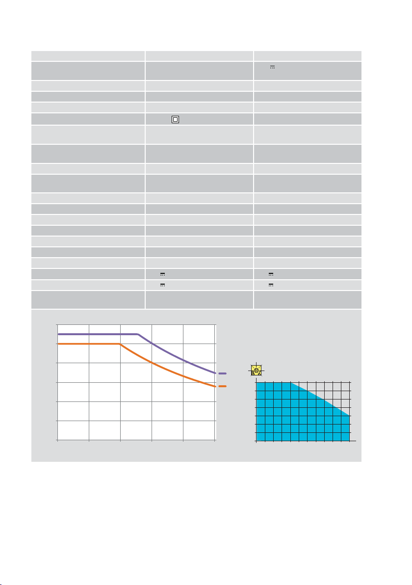
1. Technical specifications ...................................................................................................................................6
1.1 Machinery Directive .................................................................................................................................................7
1.2 Dimensions ...............................................................................................................................................................7
2. Standard installation ......................................................................................................................................8
3. Main components ..............................................................................................................................................9
4. Mechanical installation .................................................................................................................................10
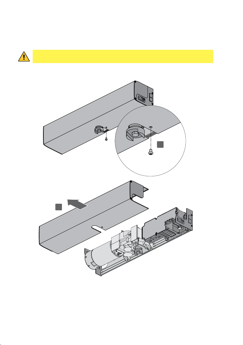
4.1 Removing the casing ...........................................................................................................................................10
5. Installation with SBS sliding arm ...............................................................................................................11
6. Installation with SBA articulated arm .............................................................................................................12
7. Installation with SPRINTBRAS 3-lever articulated arm ...........................................................................13
8. Electrical connections ......................................................................................................................................14
8.1 Electrical connections for 230 V~ power supply .................................................................................................14
8.2 Electrical connections for 24 V power supply ..........................................................................................15
8.3 Electromagnetic emissions ....................................................................................................................................15
9. Connecting the power supply .........................................................................................................................16
10. Commands ......................................................................................................................................................16
10.1 Testable safety devices .........................................................................................................................................16
11. Outputs and accessories ...............................................................................................................................17
11.1 Function selector button ....................................................................................................................................18
11.2 Example of installation with function selector COMH- COMK ................................................................19
11.2.1 Connections PASS24 .............................................................................................................................................................19
11.2.2 Connections REM ...................................................................................................................................................................19
12. Adjustments .....................................................................................................................................................20
12.1 Enabling procedure ..................................................................................................................................................20
12.2 Dip-switches .............................................................................................................................................................20
12.3 Trimmers ..................................................................................................................................................................21
12.4 Signals ......................................................................................................................................................................21
13. Door requisites for Low Energy use .............................................................................................................22
14. Start-up ...........................................................................................................................................................23
15. Troubleshooting ..............................................................................................................................................24
16. Routine maintenance plan ............................................................................................................................25