manuals.online logo
Brands
  1. Home
  2. •
  3. Brands
  4. •
  5. DIGITAL YACHT
  6. •
  7. Marine Equipment
  8. •
  9. DIGITAL YACHT AIS LifeGuard Datasheet

DIGITAL YACHT AIS LifeGuard Datasheet

DIGITAL YACHT LTD
AIS LifeGuard Quick Start Guide
QUICK START AIS LIFE GUARD V1.00
4. Operation
When powered up, the AIS LIFEGUARD will emit a short eep and the Green and Red LEDs will quickly flash
for a out 1 second and then the Green LED will stay on. This is the normal state of the AIS LIFEGUARD and
indicates that it is working correctly.
Every time that a valid !AIVDM message is received from the AIS system, the Green LED will riefly flash which
indicates that correct NMEA 0183 data communication is taking place.
The AIS LIFEGUARD checks all MSG1 and MSG14 AIS Sentences to see if an AIS SART/MOB/EPIRB has
een activated or tested. If it detects one of these conditions, then AIS LIFEGUARD alarms in the following way;
ALARM TYPE RED LED INT BUZZER EXT BUZZER MUTE ALARM
REAL CONTINUOUS CONTINUOUS CONTINUOUS MANUAL
TEST FLASH x5 BEEP x5 SILENT AUTOMATIC
A Real Alarm will cause all audi le and visual alarm indications to occur and can only e “Muted” y someone
pressing the Mute/Reset utton. A short press of the Mute/Reset utton will cause the Internal and External
uzzers to silence ut the Red Alarm LED will stay illuminated to show that an alarm condition has occurred and
that the MMSI num er of the SART that caused the alarm is stored in memory and will not cause another alarm.
The AIS LIFEGUARD will alarm again if it detects another alarm message from a SART with a different MMSI
num er. The AIS LIFEGUARD can store up to 20 different MMSI num ers of SARTs that have activated the
Alarm. Each time a SART makes the AIS LIFEGUARD alarm, the Mute/Reset utton must e pushed to silence
that particular alarm.
After an emergency situation has finished and one or more alarms have occurred and een silenced y pressing
the Mute/Reset switch, the AIS LIFEGUARD should e RESET to make it forget all of the previous MMSI
num ers of SARTs that have triggered an alarm. To RESET the AIS LIFEGUARD, press and hold the
Mute/Reset switch for 4 seconds until the Internal Buzzer eeps once and the RED Alarm LED goes out.
Most AIS SARTs have a test mode and the AIS LIFEGUARD allows you to easily test the AIS SARTs efore
commencing a voyage. When the AIS LIFEGUARD detects a SART in test mode, it Beeps the Internal Buzzer
and flashes the RED Alarm LED five times. If you have multiple AIS SARTs to test, it is recommended that you
test them one at a time. Activate the AIS SART test mode, and at the end of the test, the AIS LIFEGUARD will
eep and flash to indicate the test has worked, efore automatically returning to normal operation.
NOTE – the AIS LIFEGUARD has a Self-Test mode which is entered if you ress and hold the Mute/Reset
button whilst the AIS LIFEGUARD owers u . In Self-Test mode the two LEDs and the Internal and External
buzzers are turned ON, which is useful for testing that everything is working correctly. To exit Self-Test Mode
sim ly release the Mute/Reset switch.
DIGITAL YACHT LTD
AIS LifeGuard Quick Start Guide
QUICK START AIS LIFE GUARD V1.00
Installation & Quick Start Guide
AIS LifeGuard MOB Alarm
1. Introduction
Congratulations on the purchase of your AIS LifeGuard MOB Alarm. It is recommended that your this product is
installed y a professional installer.
Before oper ting the unit you should f mili rise yourself with this Quick St rt Guide nd the
user m nu ls for ny equipment you wish to connect it to.
2. Before you start
You will need the following items and tools to complete and test the installation:
• The AIS LIFEGUARD
• A working AIS Receiver or Transponder with an NMEA 0183 Output
• An AIS SART
• External Buzzer (optional)
• Access to 12V or 24V DC power supply where the unit is to e installed.
• M3 or M4 screws or other fixings appropriate to the mounting location.



DIGITAL YACHT LTD
AIS LifeGuard Quick Start Guide
QUICK START AIS LIFE GUARD V1.00
3. Installation
Before starting installation select a suita le location for the AIS LIFEGUARD. Below is a dimensioned drawing
showing the mounting holes and ca le entry point. The unit is water resistant; however it should e installed
elow deck in a dry location. When locating the unit you should consider:
• Routing of power/data.
• Provision of sufficient space around the unit for ca le connections.
• Easy access to the unit to Mute/Reset Alarms.
• That the internal alarm is audi le at the intended location.
• Maintaining the compass safe distance of 0.5m.
Fixing loc tion dr wing
Inst ll tion Step 1
• Fix the AIS LIFEGUARD to a ulkhead or flat surface using suita le fixings (not supplied). Note that
the unit may e installed in any orientation.
Inst ll tion Step 2 - Power
• Provide power connections to the unit. Power is connected to the four core PWR/DATA ca le on the
Red and Black wires. The Red wire is the positive (+) connection. The Black wire is the negative (-)
connection.
• Connect the stripped wires to the nearest source of primary 12V or 24V DC power, It is
recommended that the AIS LIFEGUARD is wired to the same circuit reaker/switch as the AIS
system, so that the two systems are always on together. Ensure th t the supply to the AIS
LIFEGUARD is correctly fused. A 1A fuse or circuit bre ker is recommended.
DIGITAL YACHT LTD
AIS LifeGuard Quick Start Guide
QUICK START AIS LIFE GUARD V1.00
Inst ll tion Step 3 – Connection to AIS System
• The AIS LIFEGUARD’s NMEA 0183 Input on the Power/Data ca le, needs to e connected to the
NMEA0183 output of an AIS Receiver or Transponder.
• If the AIS is already connected to a Chart Plotter, then you must wire the AIS LIFEGUARD in parallel
so that the AIS system is sending the same NMEA 0183 to the AIS LIFEGUARD as it is sending to
the Chart Plotter. NMEA 0183 outputs are designed to drive at least 2 or 3 NMEA 0183 inputs and
connecting the AIS LIFEGUARD in parallel should have no detrimental effect on the installation.
Inst ll tion Step 4 – Connecting n Extern l Buzzer (Al rm)
• The AIS LIFEGUARD has a 95dB internal uzzer which for many vessels will e loud enough.
However on larger/noisier vessels, it is recommended to fit an External Buzzer (not supplied).The
“Ext Buzzer –“ Yellow wire on the power/data ca le can drive an external DC powered
Buzzer/Klaxon/Alarm which should e wired as follows;
AIS LIFEGUARD WIRES
ORANGE = NMEA Input +
BROWN = NMEA Input -

This manual suits for next models

1

Other DIGITAL YACHT Marine Equipment manuals

DIGITAL YACHT 4GXtream Long Range WiFi Kit Quick guide

DIGITAL YACHT

DIGITAL YACHT 4GXtream Long Range WiFi Kit Quick guide

DIGITAL YACHT BM100 Quick guide

DIGITAL YACHT

DIGITAL YACHT BM100 Quick guide

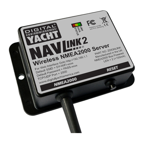
DIGITAL YACHT NAVLINK2 Quick guide

DIGITAL YACHT

DIGITAL YACHT NAVLINK2 Quick guide

DIGITAL YACHT PilotLink2 User manual

DIGITAL YACHT

DIGITAL YACHT PilotLink2 User manual

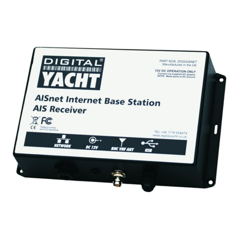
DIGITAL YACHT AISnet Internet Base Station Datasheet

DIGITAL YACHT

DIGITAL YACHT AISnet Internet Base Station Datasheet

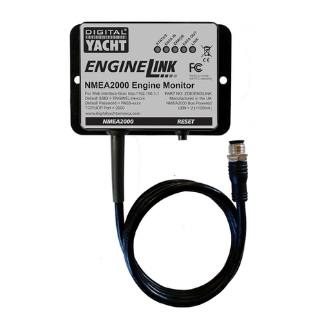
DIGITAL YACHT ENGINELINK NMEA 2000 ENGINE MONITOR Quick guide

DIGITAL YACHT

DIGITAL YACHT ENGINELINK NMEA 2000 ENGINE MONITOR Quick guide

DIGITAL YACHT AQUA COMPACT PRO MARINE PC Quick guide

DIGITAL YACHT

DIGITAL YACHT AQUA COMPACT PRO MARINE PC Quick guide

DIGITAL YACHT veKonvert Gateway Quick guide

DIGITAL YACHT

DIGITAL YACHT veKonvert Gateway Quick guide

DIGITAL YACHT HSC100 Datasheet

DIGITAL YACHT

DIGITAL YACHT HSC100 Datasheet

DIGITAL YACHT Aqua PC Q User manual

DIGITAL YACHT

DIGITAL YACHT Aqua PC Q User manual

DIGITAL YACHT Fusion 700 Series Specification sheet

DIGITAL YACHT

DIGITAL YACHT Fusion 700 Series Specification sheet

DIGITAL YACHT ZDIGAQU100N Datasheet

DIGITAL YACHT

DIGITAL YACHT ZDIGAQU100N Datasheet

Popular Marine Equipment manuals by other brands

Ocean Sonics Coastal Acoustic Drifting Buoy user guide

Ocean Sonics

Ocean Sonics Coastal Acoustic Drifting Buoy user guide

MAX PROP WHISPER 5 BLADES installation instructions

MAX PROP

MAX PROP WHISPER 5 BLADES installation instructions

auto maskin LT Series user manual

auto maskin

auto maskin LT Series user manual

Facnor LS installation manual

Facnor

Facnor LS installation manual

Hochiki YBO-BS installation instructions

Hochiki

Hochiki YBO-BS installation instructions

Lake Lite Solar Marine Lite LL-SML Series manual

Lake Lite

Lake Lite Solar Marine Lite LL-SML Series manual

LCD Concepts MEH-4P-F user manual

LCD Concepts

LCD Concepts MEH-4P-F user manual

Autocall A4098-5217 installation instructions

Autocall

Autocall A4098-5217 installation instructions

Raymarine ST40 Speed Owner's handbook

Raymarine

Raymarine ST40 Speed Owner's handbook

SR MARINER DDM-1 installation instructions

SR MARINER

SR MARINER DDM-1 installation instructions

DS18 MP4TP.4A owner's manual

DS18

DS18 MP4TP.4A owner's manual

Lymtech Ohmex SonarMite MTX manual

Lymtech

Lymtech Ohmex SonarMite MTX manual

DMP Electronics 1119 installation guide

DMP Electronics

DMP Electronics 1119 installation guide

Dometic Optimus EPS Installation and user manual

Dometic

Dometic Optimus EPS Installation and user manual

Lowrance X-20 Installation and operating instructions

Lowrance

Lowrance X-20 Installation and operating instructions

auer AS1 manual

auer

auer AS1 manual

Kohler 40EFOZ Operation guide

Kohler

Kohler 40EFOZ Operation guide

EMS FireCell FC-171-001 installation guide

EMS

EMS FireCell FC-171-001 installation guide

manuals.online logo
manuals.online logoBrands
  • About & Mission
  • Contact us
  • Privacy Policy
  • Terms and Conditions

Copyright 2025 Manuals.Online. All Rights Reserved.