Dea LOOK 351/SC Product manual

LOOK
Operatore elettromeccanico per cancelli ad anta battente
Istruzioni d’uso ed avvertenze
Electro-mechanical operator for swing gates
Operating instructions and warnings
Opérateur électromécanique pour portails battants
Notice d’emploi et avertissements
Elektromechanischer Antrieb für Flügeltore
Bedienungsanleitung und Hinweise
Operador electromecánico para puertas con hoja batiente
Instrucciones de uso y advertencias
Operador electromecânico para portões de folha batente
Instruções para utilização e advertências
Siłownik elektromechaniczny do bram skrzydłowych
Instrukcja montażu i użytkowania
I6270XX Rev. 12_1 (03-05-17)

La Dichiarazione di Incorporazione può essere consultata sul sito
The Declaration of Incorporation may be consulted by entering
La Déclaration d’Incorporation peut être vérifié à l’adresse
Die Einbauerklärung kann abgerufen werden auf der Homepage
La Declaracion de Incorporación puede ser consultada en la dirección de internet
A Declaração de Incorporação pode ser consultada em
Deklarację Zgodności można skonsul tować wchodząc na st ronę
Декларация о регистрации можно ознакомиться, введя
http://www.deasystem.com
Nome ed indirizzo della persona autorizzata a costituire la
Documentazione Tecnica pertinente:
DEA SYSTEM S.p.A.
Via Della Tecnica, 6
36013 PIOVENE ROCCHETTE (VI) - ITALY
LIEVORE TIZIANO
Amministratore

7
LOOK
Electro-mechanical ram
for swing gates
Operating instructions and warnings
Index
1Warnings Summary 76Start-up 11
2Product Description 9 6.1 Installation Test 11
3Technical data 9 6.2 Unlocking and manual operation 11
4Installation and Assembly 97Maintenance 12
5Electrical Connections 10 8Product Disposal 12
1 WARNINGS SUMMARY
WArNINg! ImpOrTANT sAfETy INsTrucTIONs. cArEfuLLy rEAd ANd fOLLOW ALL WArNINgs ANd INsTruc
-
TIONs ThAT AccOmpANy ThE prOducT sINcE INcOrrEcT INsTALLATION cOuLd cAusE hArm TO pEOpLE, ANImALs
Or ThINgs. WArNINgs ANd INsTrucTIONs prOvIdE ImpOrTANT INfOrmATION rEgArdINg sAfETy, INsTALLATION,
usE ANd mAINTENANcE. KEEp ThE INsTrucTIONs TOgEThEr ThE TEchNIcAL dOcumENTATION ANd fOr fuTurE
rEfErENcE.
WARNING The device may be used by children of less than 8 years of age, people with
reduced physical, mental or sensory impairment, or generally anyone without experience
or, in any case, the required experience provided the device is used under surveillance or
that users have received proper training on safe use of the device and are aware of the
dangers related to its use.
WARNING Do not allow children to play with the device, the xed commands or the ra-
dio controls of the system.
WARNING Product use in abnormal conditions not foreseen by the manufacturer may
generate hazardous situations; meet the conditions indicated in these instructions.
WARNING DEA System reminds all users that the selection, positioning and installa-
tion of all materials and devices which make up the complete automation system, must
comply with the European Directives 2006/42/CE (Machinery Directive), 2014/30/UE
(electromagnetic compatibility), 2014/35/UE (low voltage electrical equipment). In order
to ensure a suitable level of safety, besides complying with local regulations, it is advis-
able to comply also with the above mentioned Directives in all extra European countries.
WARNING Under no circumstances use the device in an explosive atmosphere or in
areas that may be corrosive or could damage product parts. Check that the temperatures
at the installation site are suitable and comply with the temperatures declared on the
product label.
WARNING When working with the “dead man” switch, make sure that there are no pe-
ople in the area where the automatism is being used.
WARNING Check that there is a switch or an omni polar magneto-thermal circuit bre-
aker that enables complete disconnection in case of over voltage category III conditions
installed upstream from the power system.

8
WARNING To ensure an appropriate level of electrical safety always keep the 230V
power supply cables apart (minimum 4mm in the open or 1 mm through insulation) from
low voltage cables (motors power supply, controls, electric locks, aerial and auxiliary
circuits power supply), and fasten the latter with appropriate clamps near the terminal
boards.
WARNING If the power cable is damaged, it must be replaced by the manufacturer or
its technical assistance service or, in any case, by a person with similar qualications to
prevent any risk.
WARNING All installation, maintenance, cleaning or repair operations on any part of
the system must be performed exclusively by qualied personnel with the power supply
disconnected working in strict compliance with the electrical standards and regulations
in force in the nation of installation.
Cleaning and maintenance destined to be performed by the user must not be performed
by unsupervised children.
WARNING Using spare parts not indicated by DEA System and/or incorrect re-assem-
bly can create risk to people, animals and property and also damage the product. For this
reason, always use only the parts indicated by DEA System and scrupulously follow all
assembly instructions.
WARNING Changing the closing intensity could lead to dangerous situations. Therefore,
qualied personnel should only perform increases to the closing force. After adjustment,
compliance with regulatory limits values should be detected with a force impact-mea-
suring instrument. The sensitivity of the obstacle detection may be adjusted gradually
to the door (see programming instructions). The anti-crushing device operation must be
checked after each manual adjustment. Manual modication of the force can only be
done by qualied personnel by performing the measurement test according to EN 12445.
Modications to the force adjustment must be documented in the machine manual.
WARNING The compliance of the internal sensing obstacles device to requirements
of EN12453 is guaranteed only if used in conjunction with motors tted with encoders.
WARNING Any external security devices used for compliance with the limits of impact
forces must be conform to standard EN12978.
WARNING In compliance with EU Directive 2012/19/EU on waste electrical and elec-
tronic equipment (WEEE), this electrical product should not be treated as municipal
mixed waste. Please dispose of the product and bring it to the collection for an appropri-
ate local municipal recycling.
EvEryThINg ThAT Is NOT ExprEssLy prOvIdEd fOr IN ThE INsTALLATION mANuAL Is NOT ALLOWEd. cOrrEcT Op
-
ErATOr OpErATION Is ONLy ENsuEd WhEN ThE rEpOrTEd dATA Is rEspEcTEd. ThE cOmpANy dOEs NOT rEspONd
fOr dAmAgE cAusEd by fAILurE TO cOmpLy WITh ThE INsTrucTIONs cONTAINEd IN ThIs mANuAL. WIThOuT Af
-
fEcTINg ThE EssENTIAL fEATurEs Of ThE prOducT, ThE cOmpANy rEsErvEs ThE rIghT TO mAKE ANy chANgEs
dEEmEd ApprOprIATE ANd AT ANy TImE IN OrdEr TO TEchNIcALLy, sTrucTurALLy ANd cOmmErcIALLy ImprOvE
ThE prOducT WIThOuT bEINg rEquIrEd TO updATE ThIs dOcumENT.

9
2 PRODUCT DESCRIPTION
Models and contents of the package
LOOK identies a family of operators with different characteristics as regards the supply voltage, the reversibility and the presence
of the encoder.
LOOK is designed for installation in residential swing gates, is composed primarily of a mechanical gear motor that drives the lead
screw fastened to the front attachment by means of the adjustment screw.
LOOK is completed by a set of accessories listed in the “PRODUCT ACCESSORIES” table (page 49).
Inspect the “Contents of the Package” (Pic. 1) and compare it with your product for useful consultation during assembly.
Transport
LOOK is always delivered packed in boxes that provide adequate protection to the product, however, pay attention to all information
that may be provided on the same box for storage and handling.
3 TECHNICAL DATA
351/SC
- 352/SC -
351EN/SC
355/SC
- 356/SC -
355EN/SC
353/SC -
354/SC
357/SC -
358/SC
371/SC -
371EN/SC
- 372/SC
373/SC
- 374/SC -
373EN/SC
371E/SC
Motor power supply voltage (V) 230 V ~ ±10% (50/60 Hz) 24 V
Absorbed power (W) 300 60 50
Max Thrust (N) 1650 1200 1000 500
Duty cycle (cycles/hour) 22 - 25 (351EN) 40 10
Maximum n° of operations in 24 hour 110 110 50
Built-in capacitor (µF) 8 10 /
Operating temperature range (°C) -20÷50 °C
Motor thermal protection (°C) 150 /
Opening time 90° (s) 16 12,5 17 13,5 14 15 15
Weight of product with package (Kg) 9 9,5 9 9,5 9
Protection degree IP24
4 INSTALLATION AND ASSEMBLY
4.1 For a satisfactory installation of the product is important to:
• Verify that the gate complies with the legal requirements and then dene the complete project of the installation;
• Verify that the gate is well balanced and that it has no points of friction in opening and closing;
• Identify an area that allows a smooth and safe manual operation of the operator;
• Verify that the operator bulk (Pic. 2) is compatible with the area chosen for the tting (Pic. 3);
• Use the length/weight graphic and the provided installations dimensions (Pic. 4) evaluating whether you prefer a 90° or higher ope -
ning (Pic. 4).
4.2 Dened and satised these prerequisites, proceed to the assembly:
• Fix the rear junction to the pillar bu welding (Pic. 5);
• Fix the front junction to the gate by welding (Pic. 6);
• Keeping the motor in a horizontal position, mount it rst to the front bracket, then to the rear bracket (Pic. 7) ensuring that installation
dimensions shown in Picture 4 are respected.
WARNING In order to make the structure sufciently strong, reinforcement plates to be xed to attachments may be necessary.
WARNING Grease pins before assembly.

10
4.3 How to unlock the operator
WARNING Disconnect the power supply from the control panel before releasing the operator. In case you cannot turn the power
off, you will necessarily have to re-lock the motor in the position in which it was unlocked.
• Turn the cap placed on the back of LOOK in order to discover the underlying shaped hole;
• Insert the release key inside the shaped hole paying attention to the direction of insertion (Pic. 8.a);
• Rotate 90 degrees (counterclockwise to unlock, clockwise to lock ) the release key (Pic. 8.b).
WARNING Remember to protect the lock with the respective cover so that the operator is protected by water or powder (even when it
remains unlocked for a long time).
WARNING During this operation gate may perform uncontrolled movements: operate with extra care so to avoid any risk.
4.4 Adjustment of the limit-switches
After the installing, limit switches must be adjusted (only for models that foresee them) as follows (Pic. 9):
WARNING When adjusting the limit switches, take away the little cover of the extrusion using a screwdriver and check the correct
internal microswitches are moving (Pic. 10).
• Unscrew the A xing nuts so to operate on C and D screws
• Adjust opening and closing limit switches
• Screw the A xing screws by keeping C and D blocked by a screwdriver so to maintain the adjustments.
WARNING While closing the inspection cover, use silicone to seal the leak (Pic. 11).
5 ELECTRICAL CONNECTIONS
WARNING For adequate electrical safety, keep low safety voltage wires (controls, electro-locks, antenna, auxiliary power) clearly separate
from 230V ~ power wires (minimum 4 mm in air or 1 mm via supplementary insulation) placing them in plastic raceways and securing
them with adequate clamps near terminal boards.
WARNING All wires must be striped and unsheathed in the immediate vicinity of terminals. Keep wires slightly longer to subsequently
eliminate any excess.
WARNING To connect the encoder to the control panel, use only a dedicated cable 3x0,22mm2.
Connection for 24V and 230V
• Remove the plastic cover positioned under LOOK (Pic. 12).
• Open one of four shaped holes and choose where the cable exit
has to be (Pic. 13).
• Introduce the cable clamp and x it by its nut (Pic. 14).
• Insert the power supply cable into the clamp (coming from the
control panel): A quadrupole cable suitable for external appli -
cations with a 4x1mm² section (or 3x1mm² for 24V operators)
(minimum FROR, H05RN-F type) (Pic. 15).
Connection for 24V and 230V with limit switches
• For the operator power supply connection follow the instruc -
tions of the basic version.
• Open a second hole in the plastic cover and apply the second
provided cable clamp (a reduced M16).
• Use a 3x0,75mm² cable (not supplied) for a correct limit
switches wiring to the control panel.
24V
CLOSE
OPEN
FCC
FCA
N.C.
N.C.
FCA
COM
FCC
1(red)
2(blue)
4(brown)
5(blue)
7(brown)
6(blue)
M
CENTRALE DI COMANDO,
ELECTRONIC BOARD, ARMOIRE DE
COMMANDE,STEUERUNG, CUADRO
DE MANIOBRAS, CENTRAL DE
COMANDO, CENTRALI STERUJĄCEJ
230V
CENTRALE DI COMANDO,
ELECTRONIC BOARD, ARMOIRE DE
COMMANDE, CUADRO DE
MANIOBRAS, CENTRAL DE
COMANDO, CENTRALI STERUJĄCEJ
CLOSE
COM
OPEN
M
FCC
FCA
N.C.
N.C.
FCA
COM
FCC
1(white)
2(blue)
3(black)
4(brown)
5(blue)
7(brown)
6(blue)

11
Connection for 230V version with encoder
• For the operator power supply connection fol -
low the instructions of the basic version.
• Open a second hole in the plastic cover and
apply the second provided cable clamp (a re -
duced M16).
• Use a 3x0,75mm² (ex. H05RN-F) and follow
the diagram to correctly connect the encoder
to the control board.
• Use the cable with panduit connector supplied
in the kit to connect the previously used ca-
ble to the control board, by using the clamp 3
“poli” inside the package.
230V with encoder
M
ENCODER
}
white
green
brown
CLOSE
COM
OPEN
1(white)
2(blue)
3(black)
w
h
i
t
e
b
r
o
w
n
green
WARNING Maintain the ground conductor at a major length respect the active conductors so that, if the cable exit from its xing housing,
the active conductors tighten up as rst.
WARNING Respect the Phase-Neutral polarity of the tension as explained by the instructions manual of the control panels of LOOK.
• Re-assemble the plastic cover ensuring that any cable do not touch moving parts of the operator .
WARNING while installing, maintain a proper distance between the power cable conductors and the operator.
Program the control board to complete all adjustments. It is now possible to supply a complete installation in compliance with all
standards required for gate automation. See the instructions provided with the control panel to be connected.
Finally, verify that all adjustments operations have been correctly performed and that safety devices and unlocking device properly
work.
6 START-UP
The start-up phase is very important to ensure maximum security and compliance to regulations, including all the requirements of EN
12445 standard which establishes the test methods for testing the automation for gates.
DEA System reminds that all installation, maintenance, cleaning or repair operations on any part of the system must be performed
exclusively by qualied personnel who must be responsible of all texts requie by the eventual risk;
6.1 Installation test
The testing operation is essential in order to verify the correct installation of the system. DEA System wants to summarize the proper
testing of all the automation in 4 easy steps:
• Make sure that you comply strictly as described in paragraph 2 “WARNINGS SUMMARY”;
• Test the opening and closing making sure that the movement of the leaf match as expected. We suggest in this regard to perform
various tests to assess the smoothness of the gate and defects in assembly or adjustment;
• Ensure that all safety devices connected work properly ;
• Perform the measurement of impact forces in accordance with the standard 12445 to nd the setting that ensures compliance with
the limits set by the standard EN12453 .
WARNING Using spare parts not indicated by DEA System and/or incorrect re-assembly can create a risk to people, animals and
property and also damage the product. For this reason, always use only the parts indicated by DEA System and scrupulously follow all
assembly instructions.
6.2 Unlocking and Manual operation
In the event of malfunctions or simple power failure, release the motor (Pic. 8) and perform the operation manually.
The knowledge of the unlocking operation is very important, because in times of emergency the lack of timeliness in acting on such
a device can be dangerous.
WARNING The efcancy and safety of manual operation of the automation is guaranteed by DEA System only if the installation has
been installed correctly and with original accessories.

12
7 MAINTENANCE
Good preventive maintenance and regular inspection ensure
long working life. In the table below you will nd a listo f inspections/
maintenance operations to be programmed and executed periodi-
cally.
Consult the TROUBLE-SHOOTING” table whenever anomalies are
observed in order to nd the solution to the problem and contact
DEA System directly whenever the solution required is not provided.
INTERVENTION TYPE PERIODICITY
cleaning of external surfaces 6 months
checking of screw tightening 6 months
checking of release mechanism operation 6 months
greasing of articulated joint 1 year
TROUBLE-SHOOTING
Description Possible solutions
When the opening command is given, the leaf fails to move
and the operator’s electric motor fails to start.
The operator is not receiving correct power supply. Check all connections, fuses, and the
power supply cable conditions and replace or repair if necessary.
When the opening command is given, the motor starts but
the leaf fails to move.
Check that the unlocking system is closed (see Pic.8).
Make sure that the electronic device for electric power adjustment is in good condition.
If the piston remains at the complete end of its stroke when the gate is closed, review the
assembly procedure.
The operator jerks during movement.
If the leaf does not move freely, release the ram and readjust the rotation points.
The power of the gear motor may be insufcient for the characteristics of the gate’s wing;
check the choice of model whenever required.
The operator’s front and rear attachments bend or are not fastened correctly. Repair or
replace.
8 PRODUCT DISPOSAL
LOOK consists of materials of various types, some of which can be recycled (electrical cables, plastic, aluminum, etc. ..) while others
must be disposed of (electronic boards and components).
Proceed as follows:
1. Disconnect the power supply;
2. Disconnect and disassemble all the accessories connected. Follow the instructions in reverse to that described in the section “Installa-
tion”;
3. Remove the electronic components;
4. Sorting and disposing of the materials exactly as per the regulations in the country of sale.
WARNING In line with EU Directive 2002/96/EC for waste electrical and electronic equipment (WEEE), this electrical product must
not be disposed of as unsorted municipal waste. Please dispose of this product by returning it to your local municipal collection
point for recycling.

43
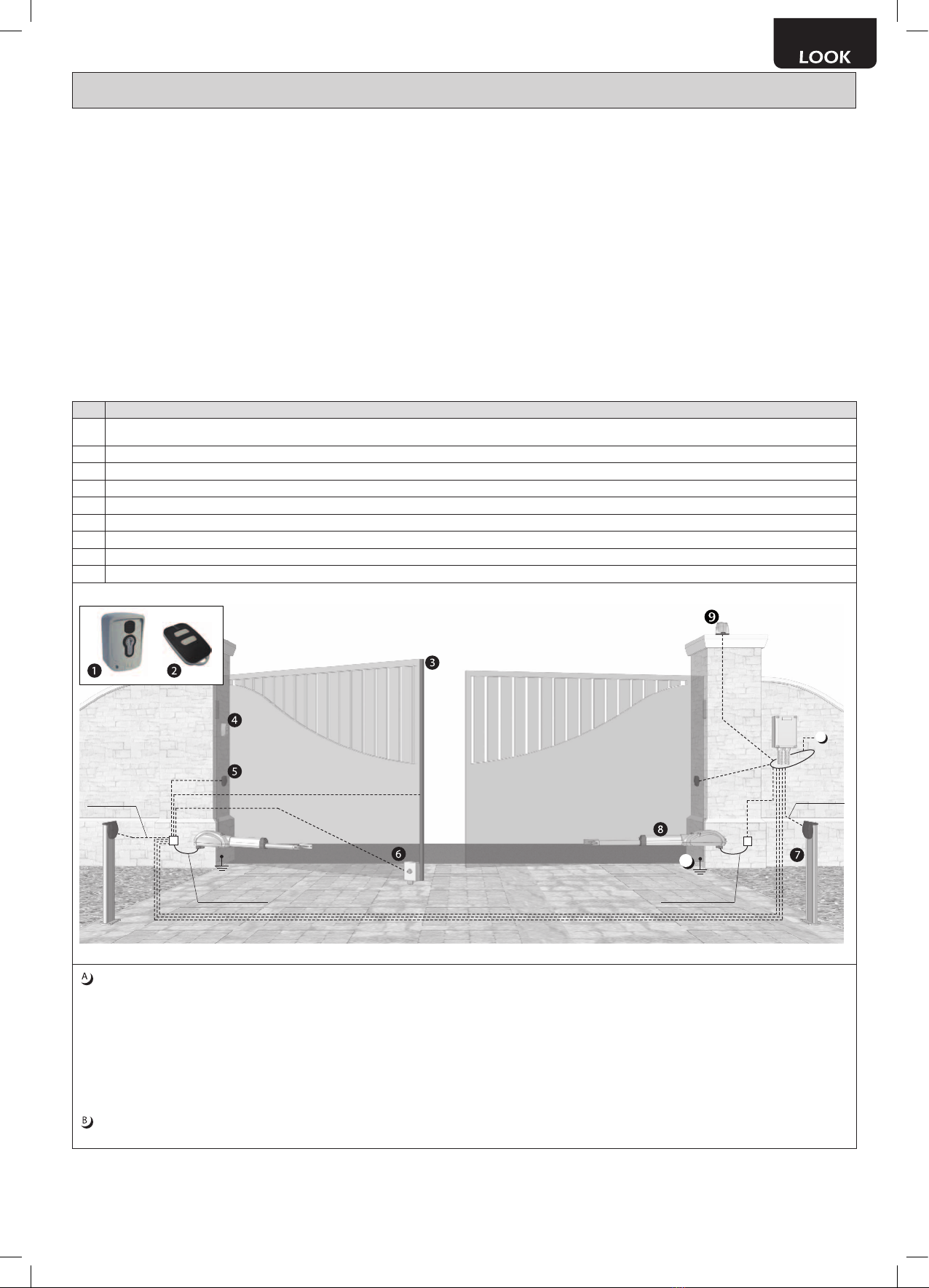
Esempio di installazion tipica - Example of typical installation - Exemple d’installation typique - Installationsbeispiel - Ejemplo de insta-
lación típica - Exemplo de instalação típica - Przyład standardowego systemu automatyzacji
Pos. Descrizione - Description - Description - Beschreibung - Descripción - Descrição - Opis
1Selettore a chiave antiscasso - Anti lock-picking key switch - Sélecteur à clé anti-intrusion - Einbruchfester Schlüsselschalter - Selector a llave antisabotaje - Interruptor de chave
burglar - Przełącznik kluczowy wandaloodporny
2Radiocomando - Remote-control - Radiocommande - Funksteuerung - Radiocomando - Comando via rádio - Nadajnik
3Safety edge - Bord sensible - Berührungssensible Schaltleiste - Borde sensible - Dispositivo sensível de protecção - Listwa bezpieczeństwa
4Selettore digitale - Radio keypad - Digicode radio - Digitalwahlschalter - Teclado digital radio - Teclado via radio - Bezprzewodowa klawiatura
5Fotocellule - Photocells - Photocellules - Fotozellen - Fotocélulas - Fotocélulas - Fotokomórki
6Elettroserratura - Electric lock - Électroserrure - Elektroschloss - Electrocerradura - Fechadura eléctrica - Elektozamek
7Colonnina Pilly 60 - Pilly 60 column - Colonnette Pilly 60 - Kleine Säule Pilly 60 - Columna Pilly 60 - Coluna Pilly 60 - Kolumienka Pilly 60
8LOOK
9Lampeggiante - Flashing light - Clignotant - Blinker - Lámpara - Intermitente - Lampa Ostrzegawcza
B
A
4 x 0,5 mm²
2 x 0,5 mm²
4x1,5 mm² (230V) o 3x1,5 mm² (24V) - 6 x 0,5 mm²
2 x 0,5 mm² - RG58
4 x 0,5 mm²
2 x 0,5 mm²
2 x 1,5 mm² 2 x 0,5 mm²
4 x 1 mm² (230V)
3 x 1 mm² (24V)
4 x 1 mm² (230V)
3 x 1 mm² (24V)
Collegarsi alla rete 230 V ± 10% 50-60 Hz tramite un interruttore onnipolare o altro dispositivo che assicuri la onnipolare disinserzione della rete, con
una distanza di apertura dei contatti ≥ 3 mm - Make the 230V ± 10% 50-60 Hz mains connection using an omnipolar switch or any other device that
guarantees the omnipolar disconnection of the mains network with a contact opening distance of 3 mm - Connectez-vous au réseau 230 V ± 10% 50-60
Hz au moyen d’un interrupteur omnipolaire ou d’un autre dispositif qui assure le débranchement omnipolaire du réseau, avec un écartement des contacts
égal à 3 mm. - Den Anschluss an das 230 V ~ ± 10% 50-60 Hz Netz mit einem Allpolschalter oder einer anderen Vorrichtung vornehmen, durch die eine
allpolige Netzunterbrechung bei einem Öffnungsabstand der Kontakte von ≥ 3 mm gewährleistet wird. - Efectuar la conexión a una línea eléctrica 230
V ± 10% 50-60 Hz a través de un interruptor omnipolar u otro dispositivo que asegure la omnipolar desconexión de la línea, con 3 mm de distancia de
abertura de los contactos. - Ligue na rede de 230 V. ± 10% 50-60 Hz mediante um interruptor omnipolar ou outro dispositivo que assegure que se desliga
de maneira omnipolar da rede, com abertura dos contactos de pelo menos 3 mm. de distância - Podłączyć się do sieci 230 V ± 10% 50-60 Hz poprzez
przełącznik jednobiegunowy lub inne urządzenie które zapewni brak zakłóceń w sieci, przy odległości między stykami ≥ 3 mm.
Collegare a terra tutte le masse metalliche - All metal parts must be grounded - Connectez toutes les masses métalliques à la terre - Alle Metallteile erden
- Conectar con la tierra todas las masas metálicas - Realize ligação à terra de todas as massas metálicas - Uziemić wszystkie elementy metalowe.
DEA System fornisce queste indicazioni che si possono ritenere valide per un
impianto tipo ma che non possono essere complete. Per ogni automatismo, in-
fatti, l’installatore deve valutare attentamente le reali condizioni del posto ed i
requisiti dell’installazione in termini di prestazioni e di sicurezza; sarà in base
a queste considerazioni che redigerà l’analisi dei rischi e progetterà nel detta-
glio l’automatismo. - DEA System provides the following instructions which are
valid for a typical system but obviously not complete for every system. For each
automatism the installer must carefully evaluate the real conditions existing
at the site. The installation requisites in terms of both performance and safety
must be based upon such considerations, which will also form the basis for
the risk analysis and the detailed design of the automatism. - DEA System
fournit ces indications que vous pouvez considérer comme valables pour une
installation-type, même si elles ne peuvent pas être complètes. En effet, pour
chaque automatisation, l’installateur doit évaluer attentivement les conditions
réelles du site et les pré-requis de l’installation au point de vue performances
et sécurité ; c’est sur la base de ces considérations qu’il rédigera l’analyse des
risques et qu’il concevra l’automatisation d’une manière détaillée. - Diese An-
gaben von DEA System können als gültig für eine Standardanlage angesehen
werden, können aber nicht erschöpfend sein. So muss der Installationsfach-
mann für jedes Automatiksystem sorgfältig die Voraussetzungen des Installa-
tionsortes sowie die Leistungs- und Sicherheitsanforderungen an die Instal-
lation abwägen; aufgrund dieser Überlegungen muss er die Risikobewertung
erstellen und genau das Automatiksystem entwickeln. - DEA System facilita
estas indicaciones que pueden considerarse válidas para una instalación tipo
pero que no pueden considerarse completas. El instalador, en efecto, tiene
que evaluar atentamente para cada automatismo las reales condiciones del
sitio y los requisitos de la instalación por lo que se reere a prestaciones y se-
guridad; en función de estas consideraciones redactará el análisis de riesgos
y efectuará el proyecto detallado del automatismo. - DEA System fornece estas
indicações que podem ser consideradas válidas para o equipamento padrão,
mas que podem não ser completas. Para cada automatismo praticamente
o técnico de instalação deverá avaliar com atenção as condições reais do
sítio e os requisitos da instalação em termos de performance e de segurança;
será em função destas considerações que realizará uma análise dos riscos e
projectará. - DEA System dostarcza wskazówek, do wykorzystania w typowej
instalacji ale nie będą one nigdy kompletne. Dla każdego typu automatyki,
instalator musi sam oszacować realne warunki miejsca montażu i wymogi in-
stalacyjne mając na uwadze przepisy dotyczące bezpieczeństwa. Na podsta-
wie zebranych informacji będzie w stanie przeanalizować zagrożenia mogące
wystąpić i zaprojektować w szczegółach automatyzację.

44
4
1
1
2
2
2
2
25 122110
810 / 1130
1010 / 1530
≥ 500 mm≥ 500 mm
≤ 250 mm
≥ 200 mm

45
Model αA
mm B
mm C
mm D
mm E
mm F
mm
320 90° 155 155 310 1100 90 0÷80
100° 125 165 316 1100 80 0÷20
520 90°
200 200 399 1500 100 0÷20
230 200 431 1500 100 150
290 200 496 1500 100 200
120° 135 200 418 1500 70 0÷20
351/SC - 351EN/SC
352/SC - 353/SC - 354/SC
371/SC - 371EN/SC - 372/SC
355/SC - 355EN/SC
356/SC - 357/SC
358/SC - 373/SC
374/SC
371/SCE
ATTENZIONE Per i modelli reversibili, a parità di lunghezza dell’anta, ridurre di 1/3 il peso ammissibile
massimo della porta rispetto a quanto indicato nel grafico “lunghezza-peso.
ATTENZIONE Se la lunghezza dell’anta è maggiore ai 2 mt o se si utilizzano modelli reversibili è necessario
installare l’elettroserratura per il blocco del cancello in posizione di chiusura.
WARNING With not self-locking models, with same leaf length, reduce of 1/3 the door admissible weight
compared to what indicated in “Length-weight” chart.
WARNING In case the leaf is more than 2 m long or in case you use not self-locking models, an electric-lock
must be installed to hold the gate in closing position.
ATTENTION Pour les modèles réversibles, avec des battants de longueur identique, réduire de 1/3 le poids
admissible maximum de la porte par rapport à ce qui est indiqué dans le graphique “ longueur-poids “.
ATTENTION Si la longueur du battant est plus de 2 mt., ou si vous utilisez un des modèles réversibles, il
faut installer une éléctro-serrure pour bloquer le portail en position de fermeture.
ACHTUNG Bei reversierbaren Modellen und gleicher Flügellänge das zulässige Höchstgewicht des Tors um
1/3 des in der Grafik „Länge-Gewicht" angegebenen Wertes reduzieren.
ACHTUNG Sollte die Flügellänge 2 m übersteigen oder sollten reversierbare Modelle verwendet werden,
muss ein Elektroschloss zur Blockierung des geschlossenen Tors installiert werden.
ATENCIÓN Para los modelos reversibles, de igual longitud que la hoja, reducir de 1/3 el peso admisible
máx. de la puerta, respecto a lo indicado en el gráfico “Longitud - Peso”.
ATENCIÓN Si el largo de la hoja es mayor de 2 mts., o se utilizan modelos reversibles, es necesario instalar
la electrocerradura para el bloqueo de la puerta en posición de cierre.
ATENÇÃO Para os modelos reversíveis, com o mesmo comprimento da folha, reduzir de 1/3 o peso máximo
do portão (com referimento ao gráfico “Comprimento-peso.
ATENÇÃO Se o comprimento da folha é maior de 2 mt ou com todos modelos reversíveis é necessário
utilizar a fechadura eléctrica para trancar o portão na posição de fecho.
UWAGA Dla modeli odwracalnych, na równej długości skrzydła, należy obniżyć maksymalny ciężar
dopuszczalny bramy o 1/3 w stosunku do wartości wskazanej na wykresie „długość-ciężar”.
UWAGA Jeśli długość skrzydła przekracza 2 m lub wykorzystywane są modele odwracalne, należy
zainstalować elektrozamek w celu zablokowania bramy na zamknięciu.
B
D
E
A
F
C
ATTENZIONE Nel caso l’operatore venisse usato in complessi condominiali,
per la movimentazione di porte o portoni pesanti o comunque in uso intensivo, si
deve saldare l’attacco posteriore come mostrato in Fig.”A” così da garantire la
durata del prodotto nel tempo.
WARNING In case the operator is subjected to intense use or to move heavy
gates, it is recommended to weld the rear bracket as shown in picture ”A” so to ensure a longer
product life.
ATTENTION En cas d’utilisation de l’opérateur pour un immeuble en copropriété pour
mouvementer grandes portes ou pour un usage intensif, il faut souder la fixation postérieur comme
montré en figure ”A” pour garantir la durée du produits dans le temps.
ACHTUNG Sollte der Antrieb für Mehrfamilienhäusern eingesetzt werden an und/oder schweren
Türen oder Toren bzw. oder bei hohem Verkehrsaufkommen, muss der verstellbare Pfostenflansch
wie in Fig. „A" gezeigt wird, fest geschweißt werden damit eine lange Lebensdauer des Produkts
gewährleistet ist.
ATENCIÓN En el caso que el automatismo venga usado en áreas condominiales, para mover
porte o portones pesados o sin embargo en un uso intensivo, se debe soldar el soporte posterior
como mostrado en Fig ”A”, así que se garantiza la duración del producto en el tiempo.
ATENÇÃO No caso do automatismo ser utilizado em condominios, em portões pesados ou para
uso intensivo, deve-se soldar o suporte posterior como indicado na figura ”A”, assim assegura-se
uma maior duração do produto.
UWAGA W przypadku gdy siłownik zostanie wykorzystany w zespole mieszkaniowym, do
otwierania drzwi wejściowych ciężkich oraz intensywnie użytkowanych, należy zespawać zaczep
tylny zgodnie z rys. A. Wydłuży to żywotność produktu.
Fig. A

46
D
A
C
A
+ Corsa in chiusura
+ Closing cycle
+ Course en fermeture
+ Schließrichtung
+ Carrera en cierre
+ Curso em fecho
+ Cykl zamyka
- Corsa in chiusura
- Closing cycle
- Course en fermeture
- Schließrichtung
- Carrera en cierre
- Curso em fecho
- Cykl zamyka
+ Corsa in apertura
+ Opening cycle
+ Course en ouverture
+ Öffnungsrichtung
+ Carrera en abertura
+ Curso em abre
+ Otwierające cykl
- Corsa in apertura
- Opening cycle
- Course en ouverture
- Öffnungsrichtung
- Carrera en abertura
- Curso em abre
- Otwierające cykl

47

48
Rosso, Red, Rouge, Rot, Rojo,
Vermelho, Czerwony, Красный
Blu, Blue, Bleu, Blau,
Azul, Niebieski, Синий
Giallo/Verde, Yellow/Green, Jaune/Vert,
Gelb/Grün, Amarillo/verde, Amarelo/Verde,
Żółty/Zielony ,Желтый/Зеленый
24V 230V Cable
13x1,5 mm² 4x1,5 mm²
H05RN-F23x1,5 mm² 4x1 mm²
FROR
2
1
2
NET /C
APRE
CHIUDE
3x1,5 mm²
APRE
CHIUDE
COMUNE
4x1 mm²
Nero, Black, Noir, Schwartz,
Negro, Preto, Czarny, Черный
Grigio, Grey, Gris, Grau, Gris,
Cinza, Szary, Серый
Marrone, Brown, Marron, Braun, Marrón,
Marrom, Brązowy, Коричневый
Giallo/Verde, Yellow/Green, Jaune/Vert,
Gelb/Grün, Amarillo/verde, Amarelo/Verde,
Żółty/Zielony ,Желтый/Зеленый

49
Tabella “ACCESSORI PRODOTTO”, Table “PRODUCT ACCESSORIES”, Tableau “ACCESSOIRES PRODUITS”, Tabelle „PRODUKTZUBEHÖR-
TEILE”, Tabla “ACCESORIOS PRODUCTO”, Tabela “ACESSÓRIOS DO PRODUTO”, Tabell “AKCESORIA DODATKOWE”.
Article
Code
Descrizione, Description, Description,
Beschreibung, Descripción, Descrição, Opis
CS320
629340
Copristelo corsa 320 / 520
Rod cover stroke 320 / 520 mm
Couvre tige course 320 / 520 mm
Kolbenabdeckung Kolbenhub 320 / 520
Cubre vástago para recorrido de 320 / 520 mm
Protecção do pistão, curso 320 / 520 mm
Osłona tłoka, wysuw 320 / 520 mm
CS520
629341
MAC-LOOK/P
629320
Prolunga per motori serie LOOK - MAC
Extension for MAC and LOOK rams
Prolongateur pour vérin MAC et LOOK
Verlängerung für Motoren der Baureihe MAC - LOOK
Extensión para pistones MAC y LOOK
Prolongamento para motores LOOK e MAC
Przedłużenie do MAC i LOOK
LOOK/SB
629380
Kit adattatore per ante in pendenza (pendenza max 8%)
Adapter kit for doors in slope. Max gradient 8%
Kit adaptateur puor vantails en pente. Pente maximale 8%
Adapterbausatz für Torügel auf Gefälle (Gefälle max. 8%)
Kit adaptador para puertas inclinadas. Inclinación max. 8%
Kit adattatore per ante in pendenza. Pendenza max 8%
Wspornik uchylny. Max nachylenie 8%
COL 515
629250
Cavo INOX 2 asole anticatuta per ante a battente
Anti-falling stainless steel cable with 2 holes for swing doors
Câble inox avec 2 xations anti-chute pour portails battants
Stahlseil Fallsicherung für Drehügel mit 2 Ösen
Cable en acero inoxidable anti-caida para puertas batientes
Cabo inox anti-queda com 2 furos para portas de batente
Linka stalowa z 2 uchwytami anty-upadkowa, do bram skrzydłowych


INSTRUCTIONS FOR THE FINAL USER
This guide has been prepared for the nal users of the automatism; the installer is required to deliver this guide and
illustrate its contents to the person in charge of the system. The latter must then provide similar instruction to all the other
users. These instructions must be carefully conserved and easily available for consultation when required.
Good preventive maintenance and frequent inspection ensures the long working life of the product. Contact the installer
regularly for routine maintenance and in event of anomaly.
SAFETY RULES
1. Always keep a safe distance from the automatism during operation and never touch any moving part.
2. Prevent children from playing near the automatism.
3. Perform the control and inspection operations prescribed in the maintenance schedule and immediately stop using the
automatism whenever signs of malfunction are noted.
4. Never disassemble parts of the product! All maintenance and repair operations must be performed only by qualied
personnel.
5. The release operation must sometimes be performed in emergencies! All users must be instructed on the use of the
release mechanism and the location of the release keys.
LOOK RELEASE MECHANISM
WARNING Disconnect the power supply from the control panel before releasing the operator. In case you cannot turn
the power off, you will necessarily have to re-lock the motor in the position in which it was unlocked.
All LOOK models are equipped with a release device which must be operated as follows:
1. Disconnect the power supply;
2. Turn the cap placed on the back of LOOK in order to discover the underlying shaped hole;
3. Insert the release key inside the shaped hole paying attention to the direction of insertion (Fig. 8.a).
4. Rotate 90 degrees (counterclockwise to unlock, clockwise to lock ) the release key (Fig. 8.b);
5. At this point LOOK is released and if no other obstructions are present, the gate is free to move;
6. The opposite procedure returns LOOK operator to normal working conditions;
7. Remember to protect the lock with the respective cover so that the operator is protected by water or powder (even when
it remains unlocked for a long time).
WARNING: During this operation gate may present uncontrolled movement: operate with extra care so to avoid any risk.
CLEANING AND INSPECTIONS
The only operation that the user can and must do is to remove branches, leaves, and any other object that might obstruct
the gate’s free movement. Warning! Always disconnect the power supply whenever performing operations on the gate!
DEA SYSTEM S.p.A. - Via Della Tecnica, 6 - ITALY
36013 PIOVENE ROCCHETTE (VI)
tel. +39 0445 550789 - fax +39 0445 550265
Internet http:\\www.deasystem.com - e-mail: [email protected]


DEA SYSTEM S.p.A.
Via Della Tecnica, 6 - 36013 PIOVENE ROCCHETTE (VI) - ITALY
tel: +39 0445 550789 - fax: +39 0445 550265
Internet: http:\\www.deasystem.com - E-mail: deasyste[email protected]
This manual suits for next models
16
Table of contents
Other Dea Gate Opener manuals

Dea
Dea OLI/N Series Product manual

Dea
Dea SWINGER Product manual

Dea
Dea BLINDO Installation guide

Dea
Dea BATTENTE ANGOLO Product manual

Dea
Dea ghost 200 Product manual

Dea
Dea LIVI 803E - 9NET Product manual

Dea
Dea Ghost 100 Series Product manual

Dea
Dea LIVI 500 Product manual

Dea
Dea ghost 200 User manual

Dea
Dea ANGOLO User manual

Dea
Dea REV Series Product manual

Dea
Dea LIVI 403E - 6NET Product manual

Dea
Dea ghost 200 Product manual

Dea
Dea SPACE Series Product manual

Dea
Dea LIVI N Series Product manual

Dea
Dea MAC STING Product manual

Dea
Dea MAC Product manual

Dea
Dea 202 E Product manual

Dea
Dea ghost 200 Product manual

Dea
Dea Ghost 100 Series Product manual