6 OF 7 IG050619-3.0
HYDROLUME
®
SLIM RGB LED STRIP LIGHT
INSTALLATION GUIDE
HYDROLUME® SLIM RGB LED Strip Light
INSTALLATION GUIDE
Wire
Gauge
10 W
.42 A
20 W
.83 A
30 W
1.3 A
40 W
1.7 A
50 W
2.1 A
60 W
2.5 A
18 AWG 134 . 68 . 45 . 33 . 27 . 22 .
16 AWG 215 . 109 . 72 . 54 . 43 . 36 .
14 AWG 345 . 174 . 115 . 86 . 69 . 57 .
12 AWG 539 . 272 . 181 . 135 . 108 . 90 .
10 AWG 784 . 397 . 263 . 197 . 158 . 131 .
INSTALLATION (676) (CONT.)
Wire
Gauge
10 W
.42 A
20 W
.83 A
30 W
1.3 A
40 W
1.7 A
50 W
2.1 A
60 W
2.5 A
70 W
2.9 A
80 W
3.3 A
100 W
4. 2 A
18 AWG 134 . 68 . 45 . 33 . 27 . 22 . 19 . 17 . 14 .
16 AWG 215 . 109 . 72 . 54 . 43 . 36 . 31 . 27 . 22 .
14 AWG 345 . 174 . 115 . 86 . 69 . 57 . 49 . 43 . 36 .
12 AWG 539 . 272 . 181 . 135 . 108 . 90 . 77 . 68 . 56 .
10 AWG 784 . 397 . 263 . 197 . 158 . 131 . 112 . 98 . 82 .
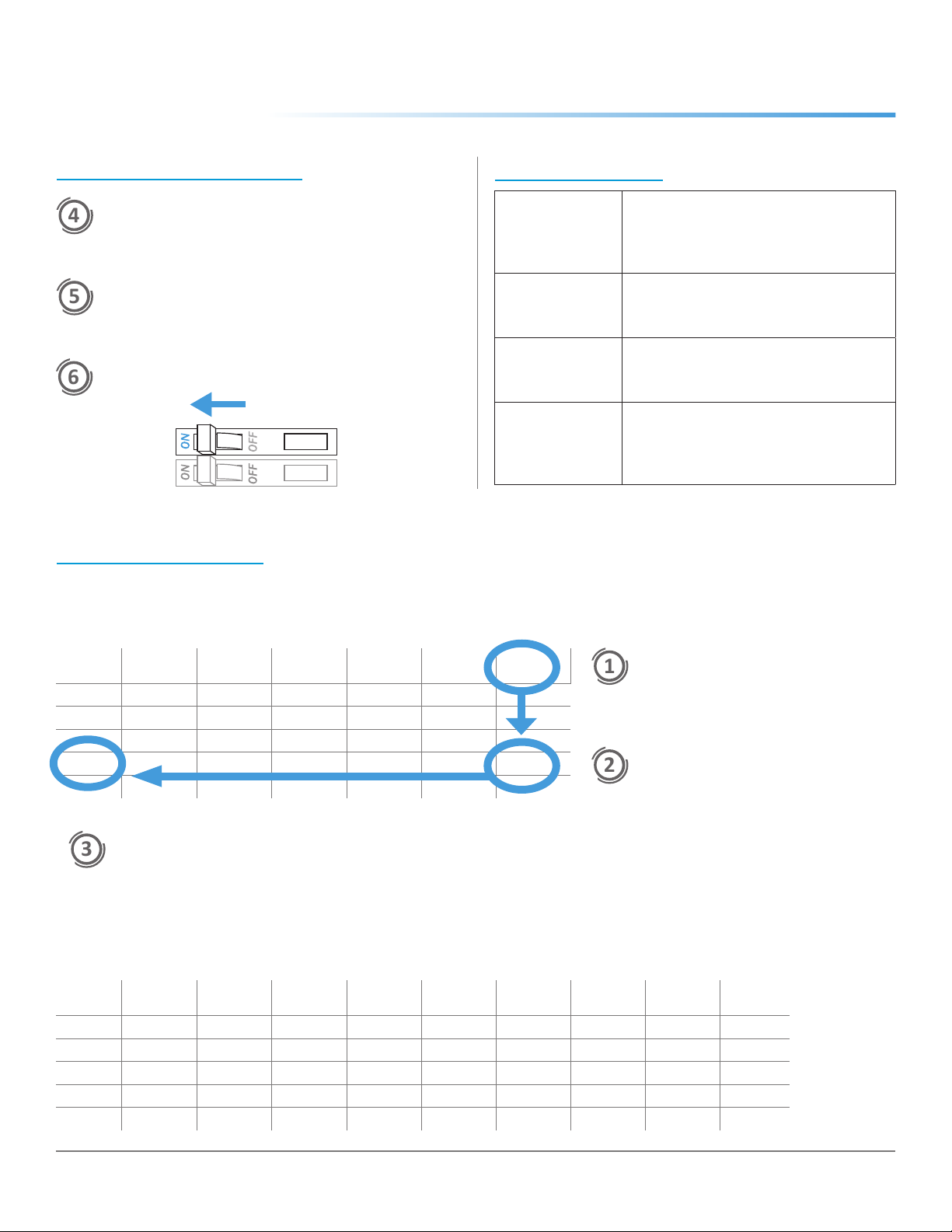
24V Voltage Drop & Wire Length Distance Chart
Example: 24V Voltage Drop & Wire Length Distance Chart
Determine load size. Let’s assume
load is 55 W. Round up to nearest
load.
Determine distance from driver
to load. Let’s assume the
distance is 90 ft.
It is recommended to install 12 AWG to
eliminate excess voltage drop.
VOLTAGE DROP CHARTS
For best performance and lumen output, ensure proper wire gauge is installed to compensate for voltage drop of low voltage circuits.
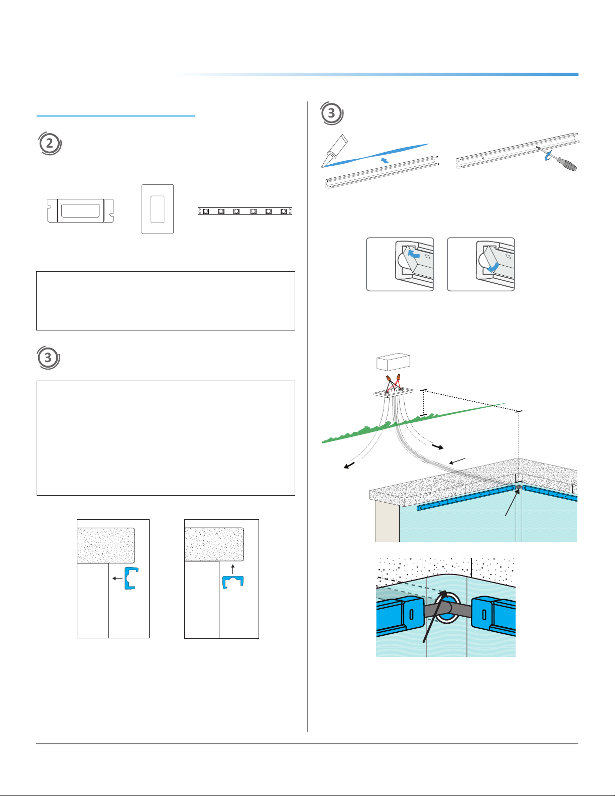
ATTACH CONTROL AND DRIVER
Verify a compable constant voltage driver is installed. Ulize
applicable wiring when installing outdoors.
REVIEW SYSTEM
Ensure all polaries are correct and connecons are secured.
TURN POWER ON AT CIRCUIT BREAKER
Shift in
brightness
and/or kelvin
• Ensure an appropriate gauge of
wire is installed between strip light
and LED driver. See VOLTAGE
DROP CHARTS.
Some LEDs
are not
functional
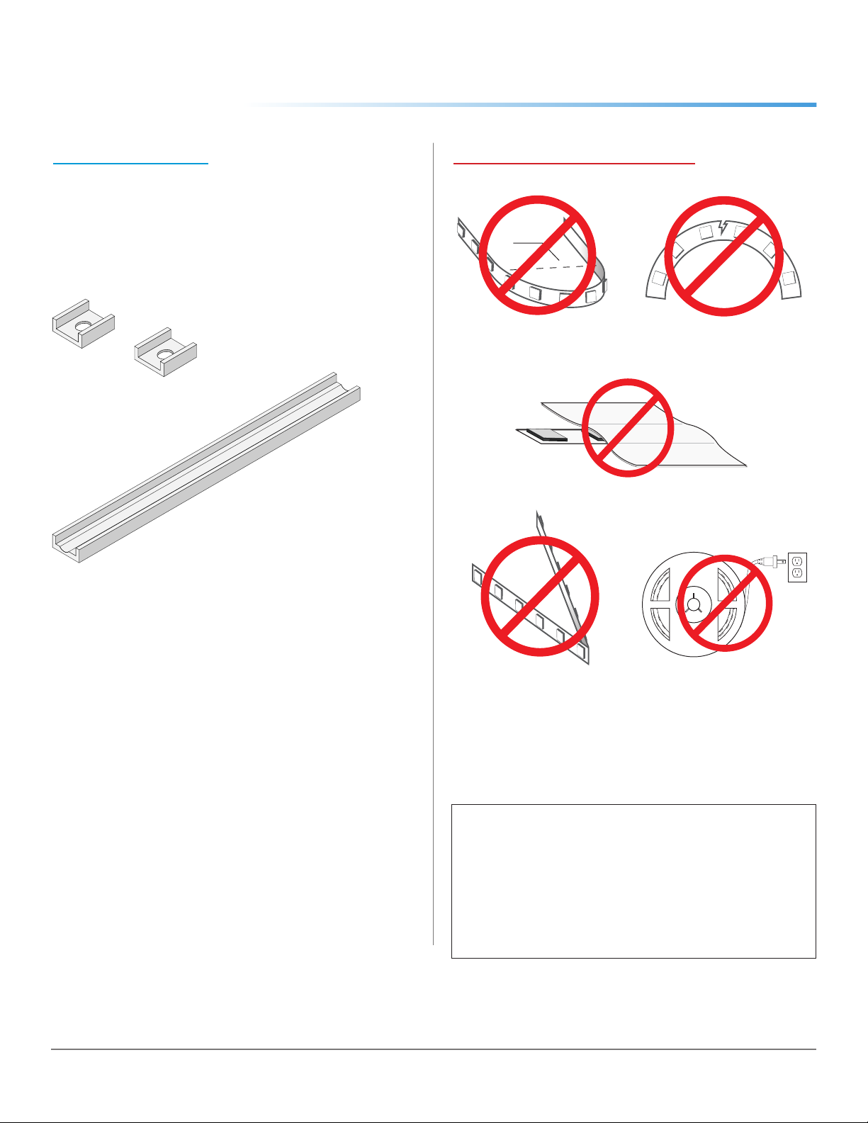
• Ensure strip light has not been bent
excessively, which could damage
circuitry.
Lights are
ickering
• Ensure a compatible driver and/or
dimming control is installed. Check
for loose connections.
Lights are
turning on/off
repeatedly
• Ensure driver is not overloaded. An
overloaded driver will trip the internal
auto-reset (of driver) repeatedly,
turning the system on/off.
TROUBLESHOOTING