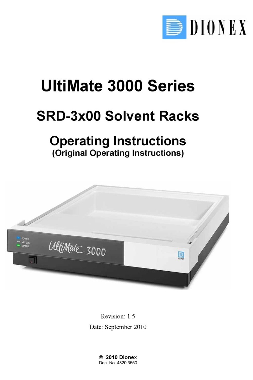
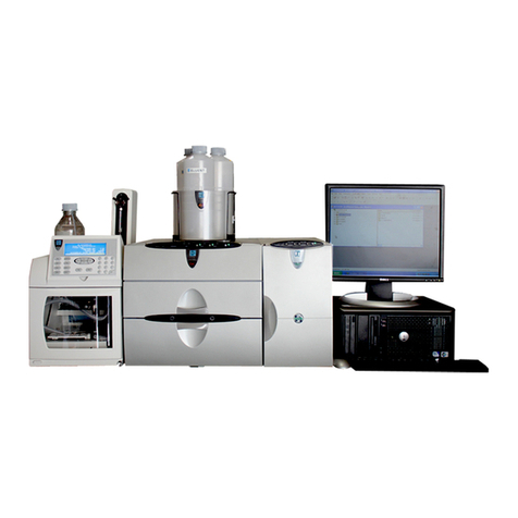
Dionex UltiMate 3000 User guide

UltiMate 3000 Nano and Cap
System Installation and Application
Revision: 1.0
Date: May 2006
© 2006 Dionex

UltiMate 3000 Nano and Cap- System Installation and Application

UltiMate 3000 Nano and Cap - System Installation and Application
i
Table of Contents
1Introduction ....................................................................................................................... 1
1.1 General ....................................................................................................................... 1
1.2 Safety Precautions...................................................................................................... 2
1.3 Unpacking .................................................................................................................. 2
1.4 Supported System Configurations.............................................................................. 3
1.5 Intended Use............................................................................................................... 5
2Installation ......................................................................................................................... 7
2.1 Facility Requirements ................................................................................................ 7
2.2 Rear Panel Connectors ............................................................................................... 8
2.2.1 Power Connection .................................................................................................. 9
2.2.2 Interfaces for Device Control................................................................................. 9
2.3 Opening the Front Panel............................................................................................. 9
2.4 Preparing the System................................................................................................ 10
3Application Examples and Fluid Connections ............................................................. 13
3.1 Manual Injection (Basic Configuration) .................................................................. 16
3.2 Direct Injection......................................................................................................... 20
3.3 Preconcentration....................................................................................................... 24
3.4 2D LC Salt Plug ....................................................................................................... 28
3.5 Comprehensive 2D LC............................................................................................. 33
3.6 Parallel LC................................................................................................................ 39
3.7 Installing a Trap Column.......................................................................................... 45
4Automated Control by Chromeleon .............................................................................. 47
4.1 General ..................................................................................................................... 47
4.2 Assigning a Flow Splitter to a Pump........................................................................ 49
4.3 Recording the Pump Pressure as a Separate Channel .............................................. 51
4.4 Synchronizing the Autosampler with a Pump.......................................................... 53
4.5 Displaying the Degasser-Related Parameters .......................................................... 54
5Soft Key Menus ............................................................................................................... 55
6Troubleshooting............................................................................................................... 57
7Routine Maintenance ...................................................................................................... 61
8Accessories and Spare Parts........................................................................................... 63
8.1 Basic Configuration Kits.......................................................................................... 64
8.1.1 Standard Devices.................................................................................................. 64
8.1.2 Biocompatible Devices ........................................................................................ 64
8.2 Direct Injection Kits................................................................................................. 64
8.2.1 Standard Devices:................................................................................................. 64
8.2.2 Biocompatible Devices: ....................................................................................... 64

UltiMate 3000 Nano and Cap- System Installation and Application
ii
8.3 Preconcentration Kits ............................................................................................... 65
8.3.1 Standard Devices:................................................................................................. 65
8.3.2 Biocompatible Devices ........................................................................................ 65
8.4 2D LC Salt Plug Kits................................................................................................ 65
8.4.1 Standard Devices.................................................................................................. 65
8.4.2 Biocompatible Devices ........................................................................................ 65
8.5 Comprehensive 2D LC Kits ..................................................................................... 65
8.5.1 Standard Devices.................................................................................................. 65
8.5.2 Biocompatible Devices ........................................................................................ 65
8.6 Parallel LC Kits........................................................................................................ 66
8.6.1 Standard Devices.................................................................................................. 66
8.6.2 Biocompatible Devices ........................................................................................ 66
8.7 Upgrade Kits ............................................................................................................ 66
8.7.1 Standard Devices.................................................................................................. 66
8.7.2 Biocompatible Devices ........................................................................................ 66
9Technical Information .................................................................................................... 67
10 Index ................................................................................................................................. 69

UltiMate 3000 Nano and Cap - System Installation and Application
1
1 Introduction
1.1 General
When working with analytical instrumentation, you should know the potential hazards of
using chemical solvents.
This document is intended as a supplementary guide to the Operating Instructions for the
individual modules of an UltiMate 3000 system (also called "the system" throughout the manual),
providing information about the installation and application of the entire system for nano and
capillary HPLC. The descriptions in the manual apply to the standard (stainless steel) and
biocompatible versions of the system modules. If some detail applies to only one version, the
version is identified by name.
In order to obtain a full understanding of the system, Dionex recommends that you review this
document and the Operating Instructions for the system modules thoroughly before beginning
installation and operation of the system.
At various points throughout the document, messages of particular importance are indicated by
certain symbols:
Please note: Indicates general information intended to optimize the performance of
the instrument.
Important: Indicates that failure to take note of the accompanying information may
result in damage to the instrument.
Important: Indique que ne pas tenir compte de l'information jointe peut
endommager l'instrument.
Warning: Indicates that failure to take note of the accompanying information may
result in personal injury.
Avertissement: Indique que ne pas tenir compte de l'information jointe peut entraîner
des blessures corporelles.
The information contained in this document is subject to change without notice and should not be
construed as a commitment by Dionex. Dionex assumes no responsibility for any errors that may
appear in this document. This document is believed to be complete and accurate at the time of
publication. In no event shall Dionex be liable for incidental or consequential damages in
connection with or arising from the use of this document.
CHROMELEON®is registered trademark and UltiMate™ is a trademark of Dionex. All other
trade or company names mentioned are subject to the copyright and the property and trademark
rights of the respective companies.
All rights reserved, including those for photomechanical reproduction and storage on electronic
media. No part of this publication may be copied or distributed, transmitted, transcribed, stored in
a retrieval system, or transmitted into any human or computer language, in any form or by any
means, electronic, mechanical, magnetic, manual, or otherwise, or disclosed to third parties
without the express written permission of Dionex.

UltiMate 3000 Nano and Cap- System Installation and Application
2
1.2 Safety Precautions
To avoid the possibility of personal injury and/or damage to the UltiMate system, observe the
safety precautions for the individual system modules (→Operating Instructions for the
instruments).
Important: When connecting the capillaries, make sure that the connectors are free
from contaminants. Even minute particles may cause damage to the flow
splitter, flow control valve, and column.
Important: Lorsque vous connectez les capillaires, assurez-vous que les raccords sont
exempts de tout contaminant. Même d'infimes particules peuvent causer
des dommages au système (ex. diviseur de débit, vanne de régulation de
débit et colonne).
Please note: Use only solvents and bottled water of at least HPLC Grade (0.2 µm,
filtered), or better LC-MS Grade, and buffers that are compatible with
components in the flow path of the flow manager. If water from water
purification systems that are not properly maintained is used, polymeric
contamination may seriously damage the column and may rapidly block
solvent filters. Note the special properties of the solvents such as viscosity,
boiling point, UV absorption (UV/VIS detector), and refractive index
(refractive index detector).
Buffer concentration: Typically up to 1 mol/L.
1.3 Unpacking
All electrical and mechanical components of the system modules are carefully tested before
the instruments are shipped from the factory. After unpacking, please inspect the modules for
any signs of mechanical damage that may have occurred during transit.
Please note: Immediately report any shipping damage to both the incoming carrier and
Dionex. Shipping insurance will compensate for the damage only if
reported immediately.
Please note: Keep the original shipping container and the packing material. They
provide excellent protection for the instrument in case of future transit.
Shipping the instrument in any other packaging automatically voids the
product warranty.
Unpack the instruments as follows:
•Place the shipping container on the floor and remove the accessories kit and the power cord.
•Grasp the instrument by the sides. Slowly and carefully, pull unit out of the shipping
container and place it on a stable surface.
Important: To prevent the instrument from falling, always lift the unit by the
sides. Do not lift the unit by the packaging material or the front panel.

UltiMate 3000 Nano and Cap - System Installation and Application
3
Important: Afin d'empêcher l'instrument de tomber, saisissez-la par les côtés. Ne
soulevez l'instrument à l’aide du matériau d'emballage ou par la porte
du panneau avant.
•Remove the foam inserts.
•Check off the contents of the accessories kit pack against the accessories list.
Important: To prevent damage to the instrument when lifting or moving, always hold
it by the bottom or sides.
Important: Afin d'éviter d'endommager l'instrument lorsque que vous le soulevez ou
le déplacez, saisissez-la toujours par le bas ou les côtés de l'unité.
1.4 Supported System Configurations
For an overview of the currently available system modules, refer to the table below. If you
have any questions, do not hesitate to contact your Dionex sales representative or distributor.
Please note: For more information about the configuration of the individual modules,
refer to the related Operating Instructions.
Application UltiMate 3000 System Module Part No.
SRD-3600—Solvent rack with 6-channel vacuum degasser
(intended, e.g., for use with a DGP-3600)
—or—
SR-3000—Solvent rack for secure positioning of solvent bottles (without
degasser, intended, e.g., for use with an LPG-3400)
5035.9230
5035.9245
DGP-3600—Ternary dual low-pressure micro gradient pump
(with loading pump and micro pump in one enclosure)
Standard pump (DGP-3600M)
Biocompatible pump (DGP-3600MB)
—or—
LPG-3400—Quaternary low-pressure micro gradient pump
Standard pump (LPG-3400M)
Biocompatible pump (LPG-3400MB)
5035.0050
5037.0060
5035.0045
5037.0055

UltiMate 3000 Nano and Cap- System Installation and Application
4
Application UltiMate 3000 System Module Part No.
VWD-3100—Variable wavelength detector for one wavelength
VWD-3400—Variable wavelength detector for four wavelengths
with nano flow cell (must be ordered separately)
5074.0005
5074.0010
6074.0270
FLM-3100(B) with two 10-port micro switching valves
Standard flow manager (FLM-3100)
Biocompatible flow manager (FLM-3100B)
—or—
FLM-3200(B) with 10-port micro and 6-port nano switching valves
Standard flow manager (FLM-3200)
Biocompatible flow manager (FLM-3200B)
—or—
FLM-3300(B) with one 10-port micro switching valve
Standard flow manager (FLM-3300)
Biocompatible flow manager (FLM-3300B)
5720.0010
5721.0010
5720.0020
5721.0020
5720.0030
5721.0030
Nano HPLC
Note: These flow managers are fitted with a splitter cartridge
for a split ratio of 1:1000.
VWD-3100—Variable wavelength detector for one wavelength
VWD-3400—Variable wavelength detector for four wavelengths
with capillary flow cell (must be ordered separately)
5074.0005
5074.0010
6074.0280
FLM-3100(B) with two 10-port micro switching valves
Standard flow manager (FLM-3100)
Biocompatible flow manager (FLM-3100B)
—or—
FLM-3200(B) with 10-port micro and 6-port nano switching valves
Standard flow manager (FLM-3200)
Biocompatible flow manager (FLM-3200B)
—or—
FLM-3300(B) with one 10-port micro switching valve
Standard flow manager (FLM-3300)
Biocompatible flow manager (FLM-3300B)
5720.0015
5721.0015
5720.0025
5721.0025
5720.0035
5721.0035
Capillary
HPLC
Note: These flow managers are fitted with a splitter cartridge
for a split ratio of 1:100.
VWD-3100—Variable wavelength detector for one wavelength
VWD-3400—Variable wavelength detector for four wavelengths
with micro flow cell (must be ordered separately)
5074.0005
5074.0010
6074.0290
FLM-3100(B) with two 10-port micro switching valves
Standard flow manager (FLM-3100)
Biocompatible flow manager (FLM-3100B)
—or—
FLM-3200(B) with 10-port micro and 6-port nano switching valves
Standard flow manager (FLM-3200)
Biocompatible flow manager (FLM-3200B)
—or—
FLM-3300(B) with one 10-port micro switching valve
Standard flow manager (FLM-3300)
Biocompatible flow manager (FLM-3300B)
5720.0018
5721.0018
5720.0028
5721.0028
5720.0038
5721.0038
Micro HPLC
Note: These flow managers are fitted with a splitter cartridge
for a split ratio of 1:6.

UltiMate 3000 Nano and Cap - System Installation and Application
5
VWD-3100—Variable wavelength detector for one wavelength
VWD-3400—Variable wavelength detector for four wavelengths
with nano flow cell (must be ordered separately)
5074.0005
5074.0010
6074.0270
FLM-3100(B) with two 10-port micro switching valves
Standard flow manager (FLM-3100)
Biocompatible flow manager (FLM-3100B)
—or—
FLM-3200(B) with 10-port micro and 6-port nano switching valves
Standard flow manager (FLM-3200)
Biocompatible flow manager (FLM-3200B)
—or—
FLM-3300(B) with one 10-port micro switching valve
Standard flow manager (FLM-3300)
Biocompatible flow manager (FLM-3300B)
5720.0015
5721.0015
5720.0025
5721.0025
5720.0035
5721.0035
Monolithic
HPLC
Note: These flow managers are fitted with a splitter cartridge
for a split ratio of 1:100.
WPS-3000T(B)— Autosampler with temperature control
Standard autosampler (WPS-3000)T
Biocompatible autosampler (WPS-3000TB)
—or—
WPS-3000(B)— Autosampler without temperature control
Standard autosampler (WPS-3000)
Biocompatible autosampler (WPS-3000B)
5820.0010
5821.0010
5820.0020
5821.0020
1.5 Intended Use
The UltiMate 3000 system is designed to perform equally well as system for routine analyses
or as a sophisticated research instrument for use in capillary, nano, and micro HPLC (high
performance liquid chromatography) applications.
The system is controlled by the Chromeleon Chromatography Management System. However, it
can also be operated with other data systems, such as Analyst®(Applied Biosystems/MDS
Sciex), HyStar™ (Bruker Daltonics), or Xcalibur®(Thermo Electron Corporation). To do so,
installation of the DCMSLink (Dionex Chromatography Mass Spectrometry Link) software is
required.
Please note that the system may be operated only using the accessories originally supplied with
the system modules and within its technical specification (→page 67).
If there is any question regarding appropriate usage, contact Dionex before proceeding.
Dionex cannot be held liable for any damage, material or otherwise, resulting from inappropriate
or improper use of the system.

UltiMate 3000 Nano and Cap- System Installation and Application
6

UltiMate 3000 Nano and Cap - System Installation and Application
7
2 Installation
2.1 Facility Requirements
After unpacking the modules of the UltiMate 3000 system, allow the units to warm up for
approximately 4 hours before connecting them to the power supply. This delay allows any
condensation that might have occurred during shipping to evaporate. After 4 hours, check the
modules; if the condensation is still there, allow them to continue to warm up (without
connecting them to the mains) until the condensation is completely gone.
Install the system in the laboratory on a stable surface that is free of vibration. Make sure that the
surface is resistant to solvents. Avoid locations with extreme changes in temperature (such as
direct sunlight or drafts) and high humidity. Allow sufficient clearance behind the system for
power connections and ventilation.
Dionex recommends that you stack the individual modules of an UltiMate 3000 system, for
example, as shown below. Note that the arrangement of the system modules depends on the
application (→Application Examples and Fluid Connections, page 13).
Fig. 1: Example for an UltiMate 3000 system
Autosampler
Flow Mana
g
e
r
Pump
Solvent Rack
Detecto
r

UltiMate 3000 Nano and Cap - System Installation and Application
9
2.2.1 Power Connection
Use the power cords from the accessories kits to connect the modules to the mains. The
instruments are equipped with a standard power supply unit with an automatic voltage
selector. Thus, no adjustment is required to adapt the line voltage to local voltage
requirements.
Please note: The SRD-3600 solvent rack is usually connected to the mains via the
pump (→Fig. 2). However, an external power supply unit (part no.
6510.0004) is available as an option.
2.2.2 Interfaces for Device Control
Apart from the solvent rack, all modules of an UltiMate 3000 system can be connected to the
server PC separately. However, Dionex recommends interconnecting the modules, and then
connecting the system to the Chromeleon server PC via only one USB connection, e.g., from
the autosampler (→Fig. 2).
Please note: The SRD-3600 solvent rack can be operated with Chromeleon via the
pump.
For information about the connection ports on the system modules, as well as the connector
pinout, refer to the Operating Instructions for the respective instrument.
2.3 Opening the Front Panel
To provide easy access to the components in the instrument compartments, the front panels of
the autosampler, detector, pump, and solvent rack tilt upward. The open cover locks in its
topmost position. The front panel of the flow manager tilts downward.
Important: When lifting or moving an instrument, always lift by the bottom or sides.
Lifting the instrument by the front panel may damage the front panel door.
Important: Lorsque vous soulevez ou déplacez un instrument, saisissez la toujours par
le dessous ou les côtés l'unité. Soulever l'unité par le panneau avant risque
d'endommager la porte du panneau avant.

UltiMate 3000 Nano and Cap- System Installation and Application
10
2.4 Preparing the System
Important: The system modules are filled with 2-propanol or an isopropyl alcohol-to-
water mixture when being shipped from the factory. During initial
operation of the modules, make sure that the solvents used are miscible.
Otherwise, use an appropriate intermediate solvent.
Important: Les instruments dans un système UltiMate 3000 sont stockés sous 2-
propanol ou isopropanol et eau. Lors du démarrage initial des instruments,
assurez-vous que les solvants utilisés soient miscibles. Sinon, suivez les
étapes intermédiaires appropriées.
•Observe the information about the facility requirements when installing the system.
•Connect the drain tubing from the devices' accessories kits to the outlet of the modules to
direct liquids that might have gathered in the enclosure to the waste. To do so, you must cut
the tubing to appropriate lengths (see table below). The outlets are on the bottom right of the
devices.
Please note: You may connect the tubing as shown in Fig. 3. To do so, use the
connecting pieces from the devices' accessories kits.
Fig. 3: Connecting drain tubing
*
In addition to the outlets
described above, the flow
manager and the solvent rack
are equipped with another
outlet on the rear panel
(→note, page 11).
*
*
Connect the connecting pieces
and tubing on these outlets.
Additional outlet on the
WPS-3000T autosampler
Additional outlet on the
flow manager

UltiMate 3000 Nano and Cap - System Installation and Application
11
For the system structure shown in Fig. 3, Dionex recommends cutting the tubing to the
following lengths:
Tubing from Length (mm)
Solvent rack to pump 215
Pump to detector 133
Detector to flow manager 217
Flow manager to autosampler 272
Flow manager to Tee (for security loop) 140
Pump, detector or autosampler to Tee 30
Connect the drain tubing from the solvent rack to the pump and from the pump to the
detector as shown in Fig. 4 a. Dionex recommends connecting the drain tubing from the flow
manager as shown in Fig. 4 b. This is to avoid that the gas sensor in the flow manager is
influenced by the drain tubing from the other modules. As an alternative, you may direct the
drain tubing from the Tee of the flow manager separately to the waste container. Always
connect the drain tubing from the bottom module as shown in Fig. 4 c.
a b c
Fig. 4: Connected drain tubing
Important: The drain tube must remain below the drain port. If the drain tube is
above the drain port, the liquid may flow back into the interior and
cause damage to the instrument. Also, be careful not to use tubing that
is bent.
Important: Afin d'éviter d'endommager l'instrument, assurez-vous qu'aucune
pièce des tubes n'est placée plus haute que le port de raccordement.
Wrong Correct
Please note: In addition to the outlets described above, the flow manager and the
solvent rack are equipped with another outlet on the rear panel. Also,
the flow manager and the WPS-3000T autosampler with temperature
control have an additional outlet at the bottom right (→Fig. 3). Make
sure to connect all outlets to the required tubing as described in the
Operating Instructions for the devices!
Connecting
piece (Tee)

UltiMate 3000 Nano and Cap- System Installation and Application
12
•Prepare the individual modules as described in the Operating Instructions for the respective
instrument.
•Connect the modules on the rear panel as described in Rear Panel Connectors (→page 8).
•For examples of the fluid connections between the system modules, refer to Application
Examples and Fluid Connections (→page 13).
•Use the power cords shipped with the instruments to connect the units to the mains. Turn on
the instruments by pressing the power switch on the rear panel.

UltiMate 3000 Nano and Cap - System Installation and Application
13
3 Application Examples and Fluid Connections
Different system configurations allow you to use the UltiMate 3000 system for various
applications. For information about the related system setup and the fluid connections in the
system, refer to:
•Manual Injection (→page 16)
•Direct Injection (→page 20)
•Preconcentration (→page 24)
•2D LC Salt Plugs (→page 28)
•Comprehensive 2D LC (→page 33)
•Parallel LC (→page 39)
When installing the fluid connections in an UltiMate 3000 system, keep the following in
mind:
Important: Different fitting systems are used in an UltiMate 3000 system. Therefore,
install the capillaries and fittings only at the positions for which they are
intended.
Important: Différents types de raccords sont utilisés dans le système UltiMate 3000.
Par conséquent, installez les capillaires et les raccords uniquement dans
aux endroits où ils sont prévus.
Important: When you operate biocompatible system modules, observe the instructions
for connecting the capillaries and other components. Refer to the related
sections of the Operating Instructions for the module(s).
Important: Avant de accorder les capillaires où des autres éléments à un module
biocompatible, référez-vous aux sections correspondantes dans le mode
d'emploi pour le(s) module(s).
Important: Dionex recommends starting the fluid connections for the system modules
at the pump. Connect the capillary to the pump first and rinse thoroughly
before connecting the other end of the capillary to another module.
Important: Lorsque vous connectez les capillaires, respectez la séquence suivante:
Raccordez le capillaire à la pompe. Rincez le capillaire avant de raccorder
l'autre fin du capillaire à l'autre unité.
Important: When connecting the capillaries, make sure that the connectors are free
from contaminants. Even minute particles may cause damage to the flow
splitter, flow control valve, and column.

UltiMate 3000 Nano and Cap- System Installation and Application
14
Important: Lorsque vous connectez les capillaires, assurez-vous que les raccords sont
exempts de tout contaminant. Même d'infimes particules peuvent causer
des dommages au système (ex. diviseur de débit, vanne de régulation de
débit et colonne).
Important: Use only the capillaries shipped with the modules and original Dionex
spare capillaries.
Important: Utilisez uniquement les capillaires fournis avec les unités et les capillaires
de rechange d'origine Dionex.
Important: To connect the capillaries to an injection valve or selector valve, install
only the ferrules and fittings shipped with the capillaries.
Important: Pour brancher les capillaires à une vanne d'injection ou de sélection,
installez uniquement les ferrules et les raccords livrés avec la vanne.
Important: Reuse used fittings and ferrules only for the same capillary connection.
This is to avoid increased dead volume.
Important: La réutilisation des raccords et ferrules n’est possible que pour la
connexion capillaire d’origine, afin d’éviter l’apparition de volumes morts
Please note: The inlets of the pump's outlet units are fitted with frit holders and inline
filters. The pump is shipped with steel frits with a porosity of 0.5 µm.
Check the permeability of the filter frits at regular intervals. When the
pump delivers water at a flow rate of 2 ml/min and when the outlet is
open, the pressure should not exceed 4 bar. If necessary, replace the filter
frits (part no. 6000.0045 = 10 filter frits for DGP-3600M and LPG-3400M
pumps or 6268.0002 for 10 filter frits for DGP-3600MB or LPG-3400MB
pumps) as described in the Operating Instructions for the pump.
Please note: Keep in mind that the flow splitter in the flow manager, the flow cell in the
detector and the associated capillaries depend on the specific application
and that it might be necessary to replace them as necessary.

UltiMate 3000 Nano and Cap - System Installation and Application
15
The following flow splitters and flow cells are available:
Description Part No.
Splitter cartridge (standard) for nano HPLC applications
(split ratio 1:1000)
6720.3150A
Splitter cartridge (standard) for nano HPLC applications
(split ratio 1:300)
6720.3155A
Splitter cartridge (standard) for capillary HPLC applications
(split ratio 1:100)
6720.3160A
Splitter cartridge (standard) for capillary HPLC applications
(split ratio 1:15)
6720.3165A
Splitter cartridge (standard) for micro HPLC applications
(split ratio 1:6)
6720.3170A
Splitter cartridge (biocompatible) for nano HPLC applications
(split ratio 1:1000)
6721.3150A
Splitter cartridge (biocompatible) for nano HPLC applications
(split ratio 1:300)
6721.3155A
Splitter cartridge (biocompatible) for capillary HPLC applications
(split ratio 1:100)
6721.3160A
Splitter cartridge (biocompatible) for capillary HPLC applications
(split ratio 1:15)
6721.3165A
Splitter cartridge (biocompatible) for micro HPLC applications
(split ratio 1:6)
6721.3170A
Flow cell for nano HPLC applications 6074.0270
Flow cell for capillary HPLC applications 6074.0280
Flow cell for micro HPLC applications 6074.0290
For nano HPLC applications, the inner diameter of the capillaries is
20 µm.
For capillary HPLC applications, the inner diameter is 50 µm.
For micro HPLC applications, the inner diameter is 75 µm. If the back
pressure generated by the connecting tubing is too high, tubing with an
inner diameter of 130 µm can be used.
For applications with Monolithic columns with an inner diameter of
100 µm, the inner diameter of the connecting capillaries is 20 µm.
For applications with Monolithic columns with an inner diameter of 200
µm, the inner diameter of the connecting capillaries before the column is
50 µm. After the column, Dionex recommends an inner diameter of
20 µm.

UltiMate 3000 Nano and Cap- System Installation and Application
16
3.1 Manual Injection (Basic Configuration)
For this application, the sample is injected manually and directed to the separation column via
the switching valve in the flow manager.
Dionex recommends that you stack the system modules as shown below:
Fig. 5: Module arrangement for manual injection
The system includes the modules listed in the table below. In addition, the appropriate Basic
Configuration Kit (→section 8.1, page 64) is required.
Part No.System Module
Nano HPLC Capillary HPLC Micro HPLC Monolith. HPLC
SR-3000 5035.9200
LPG-3400 5035.0045 (standard) or 5037.0055 (biocompatible)
FLM-3300
Standard
Biocompatible
5720.0030
5021.0030
5720.0035
5021.0035
5720.0038
5021.0038
5720.0035
5021.0035
Basic Configuration Kit
Standard
Biocompatible
6720.0065
6721.0065
6720.0082
6721.0082
6720.0083
6721.0083
6720.0084
6721.0084
SR-3000 Solven
t
Rac
k
LPG-3400 Pump
FLM-3300 Flow Manager
Other manuals for UltiMate 3000
1
Table of contents
Other Dionex Laboratory Equipment manuals

Dionex
Dionex TCC-100 User manual

Dionex
Dionex AS-HV User manual

Dionex
Dionex MSQ User manual

Dionex
Dionex As User manual

Dionex
Dionex P680 User manual

Dionex
Dionex ProPac WCX-10 Assembly instructions

Dionex
Dionex DX-120 User manual

Dionex
Dionex ICS-90 User manual

Dionex
Dionex ICS-2100 User manual

Dionex
Dionex IONPAC AG9-SC GUARD COLUMN User manual

Dionex
Dionex ICS-1000 User manual

Dionex
Dionex P680 User manual

Dionex
Dionex UltiMate 3000 Series User manual

Dionex
Dionex ICS-90 User manual

Dionex
Dionex P680 User manual

Dionex
Dionex UltiMate 3000 User guide

Dionex
Dionex ICS-900 User manual

Dionex
Dionex RF-2000 User manual

Dionex
Dionex ICS-3000 User manual