Dionex ICS-1000 User manual

ICS-1000 ION CHROMATOGRAPHY SYSTEM
OPERATOR’S MANUAL
© 2003 Dionex Corporation
Document No. 031879
Revision 01
March 2003

©2003 by Dionex Corporation
All rights reserved worldwide.
Printed in the United States of America.
This publication is protected by federal copyright law. No part of this publication
may be copied or distributed, transmitted, transcribed, stored in a retrieval system, or
transmitted into any human or computer language, in any form or by any means,
electronic, mechanical, magnetic, manual, or otherwise, or disclosed to third parties
without the express written permission of Dionex Corporation, 1228 Titan Way,
Sunnyvale, California 94088-3603 U.S.A.
DISCLAIMER OF WARRANTY AND LIMITED WARRANTY
THIS PUBLICATION IS PROVIDED “AS IS” WITHOUT WARRANTY OF
ANY KIND. DIONEX CORPORATION DOES NOT WARRANT,
GUARANTEE, OR MAKE ANY EXPRESS OR IMPLIED
REPRESENTATIONS REGARDING THE USE, OR THE RESULTS OF THE
USE, OF THIS PUBLICATION IN TERMS OF CORRECTNESS, ACCURACY,
RELIABILITY, CURRENTNESS, OR OTHERWISE. FURTHER, DIONEX
CORPORATION RESERVES THE RIGHT TO REVISE THIS PUBLICATION
AND TO MAKE CHANGES FROM TIME TO TIME IN THE CONTENT
HEREINOF WITHOUT OBLIGATION OF DIONEX CORPORATION TO
NOTIFY ANY PERSON OR ORGANIZATION OF SUCH REVISION OR
CHANGES.
TRADEMARKS
MMS™ MicroMembrane™ Suppressor is a trademark of Dionex Corporation.
AES® Atlas Electrolytic Suppressor, Chromeleon®, OnGuard®, and SRS® Self-
Regenerating Suppressor are registered trademarks of Dionex Corporation.
Teflon® is a registered trademark of E.I. duPont de Nemours & Co.
Windows® is a registered trademark of Microsoft Corporation.
PRINTING HISTORY
Revision 01, March 2003

Doc. 031879-01 3/03 i
Contents
1 • Introduction
1.1 Introduction to Ion Chromatography (IC) . . . . . . . . . . . . . . . . . . . . . . .1-1
1.2 Overview of the ICS-1000 . . . . . . . . . . . . . . . . . . . . . . . . . . . . . . . . . . .1-4
1.3 About This Manual . . . . . . . . . . . . . . . . . . . . . . . . . . . . . . . . . . . . . . . .1-5
1.3.1 Safety Messages and Notes . . . . . . . . . . . . . . . . . . . . . . . . . . .1-6
1.3.2 Safety Labels . . . . . . . . . . . . . . . . . . . . . . . . . . . . . . . . . . . . . .1-8
2 • Features
2.1 Operating Features . . . . . . . . . . . . . . . . . . . . . . . . . . . . . . . . . . . . . . . . .2-1
2.1.1 Front Panel . . . . . . . . . . . . . . . . . . . . . . . . . . . . . . . . . . . . . . . .2-1
2.1.2 Top Cover . . . . . . . . . . . . . . . . . . . . . . . . . . . . . . . . . . . . . . . . .2-3
2.1.3 Component Panel . . . . . . . . . . . . . . . . . . . . . . . . . . . . . . . . . . .2-4
2.1.4 Rear Panel . . . . . . . . . . . . . . . . . . . . . . . . . . . . . . . . . . . . . . . . .2-7
2.2 Flow Schematic . . . . . . . . . . . . . . . . . . . . . . . . . . . . . . . . . . . . . . . . . . .2-9
2.3 The Chromeleon Interface . . . . . . . . . . . . . . . . . . . . . . . . . . . . . . . . . .2-11
2.3.1 The Chromeleon Main Window and Browser . . . . . . . . . . . .2-12
2.3.2 The ICS-1000 Control Panels . . . . . . . . . . . . . . . . . . . . . . . . .2-13
2.4 System Component Details . . . . . . . . . . . . . . . . . . . . . . . . . . . . . . . . .2-19
2.4.1 Vacuum Degas Assembly (Optional) . . . . . . . . . . . . . . . . . .2-19
2.4.2 Eluent Valve . . . . . . . . . . . . . . . . . . . . . . . . . . . . . . . . . . . . . .2-21
2.4.3 Pump . . . . . . . . . . . . . . . . . . . . . . . . . . . . . . . . . . . . . . . . . . . .2-21

ICS-1000 Ion Chromatography System
ii Doc. 031879-01 3/03
2.4.4 Injection Valve . . . . . . . . . . . . . . . . . . . . . . . . . . . . . . . . . . . 2-24
2.4.5 Column Heater (Optional) . . . . . . . . . . . . . . . . . . . . . . . . . . . 2-26
2.4.6 Suppressor . . . . . . . . . . . . . . . . . . . . . . . . . . . . . . . . . . . . . . . 2-27
2.4.7 DS6 Heated Conductivity Cell . . . . . . . . . . . . . . . . . . . . . . . 2-27
3 • Operation and Maintenance
3.1 Operation Overview . . . . . . . . . . . . . . . . . . . . . . . . . . . . . . . . . . . . . . . 3-1
3.2 Power Up the System . . . . . . . . . . . . . . . . . . . . . . . . . . . . . . . . . . . . . . 3-3
3.3 Start Chromeleon . . . . . . . . . . . . . . . . . . . . . . . . . . . . . . . . . . . . . . . . . 3-4
3.4 Set Up the Eluent Reservoir . . . . . . . . . . . . . . . . . . . . . . . . . . . . . . . . . 3-6
3.4.1 Prepare the Eluent . . . . . . . . . . . . . . . . . . . . . . . . . . . . . . . . . . 3-6
3.4.2 Degas the Eluent . . . . . . . . . . . . . . . . . . . . . . . . . . . . . . . . . . . 3-6
3.4.3 Filter the Eluent . . . . . . . . . . . . . . . . . . . . . . . . . . . . . . . . . . . . 3-7
3.4.4 Fill the Reservoir . . . . . . . . . . . . . . . . . . . . . . . . . . . . . . . . . . . 3-8
3.4.5 Set the Eluent Level . . . . . . . . . . . . . . . . . . . . . . . . . . . . . . . . . 3-8
3.4.6 Connect the Reservoir . . . . . . . . . . . . . . . . . . . . . . . . . . . . . . . 3-8
3.5 Check All Connections . . . . . . . . . . . . . . . . . . . . . . . . . . . . . . . . . . . . . 3-9
3.6 Prime the Pump . . . . . . . . . . . . . . . . . . . . . . . . . . . . . . . . . . . . . . . . . . 3-9
3.7 Set System Operating Conditions . . . . . . . . . . . . . . . . . . . . . . . . . . . . 3-10
3.8 Equilibrate the System and Verify Operational Status . . . . . . . . . . . 3-11
3.9 Prepare Samples . . . . . . . . . . . . . . . . . . . . . . . . . . . . . . . . . . . . . . . . . 3-12
3.9.1 Collecting and Storing Samples . . . . . . . . . . . . . . . . . . . . . . 3-12
3.9.2 Pretreating Samples . . . . . . . . . . . . . . . . . . . . . . . . . . . . . . . . 3-12
3.9.3 Diluting Samples . . . . . . . . . . . . . . . . . . . . . . . . . . . . . . . . . . 3-13

Contents
Doc. 031879-01 3/03 iii
3.10 Loading and Injecting Samples . . . . . . . . . . . . . . . . . . . . . . . . . . . . . .3-14
3.10.1 Loading Samples with a Syringe . . . . . . . . . . . . . . . . . . . . . .3-15
3.10.2 Loading Samples with a Vacuum Syringe . . . . . . . . . . . . . . .3-16
3.10.3 Loading Samples with an Autosampler . . . . . . . . . . . . . . . . .3-16
3.10.4 Injecting Samples . . . . . . . . . . . . . . . . . . . . . . . . . . . . . . . . . .3-17
3.10.5 Example Chromeleon Commands for Loading and Injecting
Samples 3-17
3.11 Process Samples . . . . . . . . . . . . . . . . . . . . . . . . . . . . . . . . . . . . . . . . .3-18
3.11.1 Manual Sample Processing . . . . . . . . . . . . . . . . . . . . . . . . . .3-18
3.11.2 Automatic (Batch) Sample Processing . . . . . . . . . . . . . . . . . .3-19
3.12 Maintenance . . . . . . . . . . . . . . . . . . . . . . . . . . . . . . . . . . . . . . . . . . . .3-21
4 • Troubleshooting
4.1 Alarms and Error Conditions . . . . . . . . . . . . . . . . . . . . . . . . . . . . . . . . .4-3
4.2 Liquid Leaks . . . . . . . . . . . . . . . . . . . . . . . . . . . . . . . . . . . . . . . . . . . . .4-9
4.3 Pump Difficult to Prime or Loses Prime . . . . . . . . . . . . . . . . . . . . . . .4-11
4.4 Pump Does Not Start . . . . . . . . . . . . . . . . . . . . . . . . . . . . . . . . . . . . . .4-13
4.5 No Flow . . . . . . . . . . . . . . . . . . . . . . . . . . . . . . . . . . . . . . . . . . . . . . . .4-14
4.6 Erratic Flow/Pressure Reading . . . . . . . . . . . . . . . . . . . . . . . . . . . . . .4-15
4.7 Excessive System Backpressure . . . . . . . . . . . . . . . . . . . . . . . . . . . . .4-15
4.8 Peak “Ghosting” . . . . . . . . . . . . . . . . . . . . . . . . . . . . . . . . . . . . . . . . .4-16
4.9 Nonreproducible Peak Height or Retention Time . . . . . . . . . . . . . . . .4-17
4.10 Abnormal Retention Time or Selectivity . . . . . . . . . . . . . . . . . . . . . .4-17
4.11 No Cell Response . . . . . . . . . . . . . . . . . . . . . . . . . . . . . . . . . . . . . . . .4-18
4.12 High Cell Output . . . . . . . . . . . . . . . . . . . . . . . . . . . . . . . . . . . . . . . . .4-18

ICS-1000 Ion Chromatography System
iv Doc. 031879-01 3/03
4.13 Baseline Noise or Drift . . . . . . . . . . . . . . . . . . . . . . . . . . . . . . . . . . . . 4-19
4.14 Vacuum Degas Assembly Does Not Run . . . . . . . . . . . . . . . . . . . . . . 4-20
5•Service
5.1 Diagnostic and Calibration Procedures . . . . . . . . . . . . . . . . . . . . . . . . 5-1
5.1.1 Chromeleon Wellness Panel Overview . . . . . . . . . . . . . . . . . . 5-2
5.1.2 Calibrating the Conductivity Cell . . . . . . . . . . . . . . . . . . . . . . 5-4
5.1.3 Calibrating the Flow Rate . . . . . . . . . . . . . . . . . . . . . . . . . . . . 5-6
5.1.4 Calibrating the Vacuum Degas Assembly . . . . . . . . . . . . . . . . 5-7
5.2 Isolating a Restriction in the Liquid Lines . . . . . . . . . . . . . . . . . . . . . . 5-7
5.3 Replacing Tubing and Fittings . . . . . . . . . . . . . . . . . . . . . . . . . . . . . . . 5-9
5.4 Rebuilding the Injection Valve . . . . . . . . . . . . . . . . . . . . . . . . . . . . . . 5-10
5.5 Cleaning and Replacing the Pump Check Valves . . . . . . . . . . . . . . . 5-11
5.6 Replacing a Pump Piston Seal and Piston Rinse Seal . . . . . . . . . . . . 5-13
5.7 Replacing a Pump Piston . . . . . . . . . . . . . . . . . . . . . . . . . . . . . . . . . . 5-17
5.8 Replacing the Waste Valve or Priming Valve O-Ring . . . . . . . . . . . . 5-18
5.9 Replacing the Conductivity Cell . . . . . . . . . . . . . . . . . . . . . . . . . . . . . 5-20
5.10 Replacing the Suppressor . . . . . . . . . . . . . . . . . . . . . . . . . . . . . . . . . . 5-22
5.11 Replacing the Column Heater . . . . . . . . . . . . . . . . . . . . . . . . . . . . . . . 5-23
5.12 Replacing the Column Heater Heat Exchanger . . . . . . . . . . . . . . . . . 5-25
5.13 Replacing the Eluent Valve . . . . . . . . . . . . . . . . . . . . . . . . . . . . . . . . 5-26
5.14 Replacing the Leak Sensor . . . . . . . . . . . . . . . . . . . . . . . . . . . . . . . . . 5-28
5.15 Priming with Isopropyl Alcohol . . . . . . . . . . . . . . . . . . . . . . . . . . . . . 5-29
5.16 Changing Main Power Fuses . . . . . . . . . . . . . . . . . . . . . . . . . . . . . . . 5-30

Contents
Doc. 031879-01 3/03 v
A • Specifications
A.1 Electrical . . . . . . . . . . . . . . . . . . . . . . . . . . . . . . . . . . . . . . . . . . . . . . . A-1
A.2 Physical . . . . . . . . . . . . . . . . . . . . . . . . . . . . . . . . . . . . . . . . . . . . . . . . A-1
A.3 Environmental . . . . . . . . . . . . . . . . . . . . . . . . . . . . . . . . . . . . . . . . . . . A-1
A.4 Front Panel . . . . . . . . . . . . . . . . . . . . . . . . . . . . . . . . . . . . . . . . . . . . . . A-2
A.5 Pump . . . . . . . . . . . . . . . . . . . . . . . . . . . . . . . . . . . . . . . . . . . . . . . . . . A-2
A.6 Detector . . . . . . . . . . . . . . . . . . . . . . . . . . . . . . . . . . . . . . . . . . . . . . . . A-3
A.7 Conductivity Cell with Heat Exchanger . . . . . . . . . . . . . . . . . . . . . . . A-3
A.8 Injection Valve . . . . . . . . . . . . . . . . . . . . . . . . . . . . . . . . . . . . . . . . . . A-3
A.9 Vacuum Degas Assembly (Optional) . . . . . . . . . . . . . . . . . . . . . . . . . A-3
A.10 Column Heater (Optional) . . . . . . . . . . . . . . . . . . . . . . . . . . . . . . . . . . A-4
B • Installation
B.1 Facility Requirements . . . . . . . . . . . . . . . . . . . . . . . . . . . . . . . . . . . . . B-1
B.2 Unpacking the ICS-1000 System . . . . . . . . . . . . . . . . . . . . . . . . . . . . B-2
B.2.1 Unpacking the Computer (North America only). . . . . . . . . . . B-4
B.2.2 Unpacking the Computer (outside North America) . . . . . . . . B-4
B.3 Installing Chromeleon . . . . . . . . . . . . . . . . . . . . . . . . . . . . . . . . . . . . . B-5
B.4 Installing the Chromeleon Software License . . . . . . . . . . . . . . . . . . . B-6
B.5 Connecting the ICS-1000 to the Chromeleon PC . . . . . . . . . . . . . . . . B-9
B.5.1 Connecting the ICS-1000 to the PC . . . . . . . . . . . . . . . . . . . . B-9
B.5.2 Connecting Additional USB Devices . . . . . . . . . . . . . . . . . . B-10
B.6 Connecting the Power Cord . . . . . . . . . . . . . . . . . . . . . . . . . . . . . . . . B-11
B.7 Turning On the ICS-1000 Power . . . . . . . . . . . . . . . . . . . . . . . . . . . . B-12

ICS-1000 Ion Chromatography System
vi Doc. 031879-01 3/03
B.8 Setting Up Chromeleon . . . . . . . . . . . . . . . . . . . . . . . . . . . . . . . . . . .B-13
B.8.1 Assigning the ICS-1000 to a Timebase . . . . . . . . . . . . . . . . .B-13
B.8.2 Assigning DX-LAN Devices to the Timebase (Optional) . . .B-16
B.9 Installing and Plumbing the Columns and Suppressor . . . . . . . . . . . .B-19
B.9.1 Column Heater Setup (Optional) . . . . . . . . . . . . . . . . . . . . . .B-19
B.9.2 Installing the Columns . . . . . . . . . . . . . . . . . . . . . . . . . . . . . .B-20
B.9.3 Installing the Suppressor . . . . . . . . . . . . . . . . . . . . . . . . . . . .B-21
B.10 Connecting the Waste Lines . . . . . . . . . . . . . . . . . . . . . . . . . . . . . . . .B-23
B.10.1 Installing the Gas Separator Waste Tube . . . . . . . . . . . . . . . .B-23
B.11 Setting Up the Eluent Reservoir . . . . . . . . . . . . . . . . . . . . . . . . . . . . .B-25
B.12 Setting Up a Chromeleon Application . . . . . . . . . . . . . . . . . . . . . . . .B-26
B.12.1 Verifying Chromeleon Communication . . . . . . . . . . . . . . . . .B-35
B.13 Setting the Eluent Level . . . . . . . . . . . . . . . . . . . . . . . . . . . . . . . . . . .B-35
B.14 Priming the Pump . . . . . . . . . . . . . . . . . . . . . . . . . . . . . . . . . . . . . . . .B-36
B.14.1 Priming the Eluent Lines with a Syringe . . . . . . . . . . . . . . . .B-36
B.14.2 Priming with the Prime Button. . . . . . . . . . . . . . . . . . . . . . . .B-38
B.15 Equilibrating the System . . . . . . . . . . . . . . . . . . . . . . . . . . . . . . . . . .B-39
B.16 Verifying Operational Status . . . . . . . . . . . . . . . . . . . . . . . . . . . . . . .B-39
B.17 Connecting an AS50 Autosampler (Optional) . . . . . . . . . . . . . . . . . .B-40
B.17.1 AS50 Configuration Requirements . . . . . . . . . . . . . . . . . . . .B-40
B.17.2 AS50 Connections . . . . . . . . . . . . . . . . . . . . . . . . . . . . . . . . .B-41
B.17.3 Enable AS50 Control of the Injection Valve . . . . . . . . . . . . .B-43
B.18 Connecting an AS40 Automated Sampler (Optional) . . . . . . . . . . . .B-44
B.19 Analog Output Connection (Optional) . . . . . . . . . . . . . . . . . . . . . . . .B-46
B.20 Pressurizing the Eluent Reservoir (Optional) . . . . . . . . . . . . . . . . . . .B-46

Contents
Doc. 031879-01 3/03 vii
B.20.1 Connecting the Gas Source (Optional) . . . . . . . . . . . . . . . . . B-47
B.20.2 Pressurizing the Eluent Reservoir (Optional) . . . . . . . . . . . . B-48
B.21 Pump Continuous Seal Wash Connections (Optional) . . . . . . . . . . . B-49
B.22 Manually Connecting to a Control Panel . . . . . . . . . . . . . . . . . . . . . B-51
B.23 Installation Troubleshooting . . . . . . . . . . . . . . . . . . . . . . . . . . . . . . . B-53
C • TTL and Relay Control
C.1 TTL and Relay Connections . . . . . . . . . . . . . . . . . . . . . . . . . . . . . . . . C-1
C.1.1 Selecting TTL Input Functions and Control Types. . . . . . . . . C-3
C.2 Controlling TTL and Relay Outputs . . . . . . . . . . . . . . . . . . . . . . . . . . C-5
C.3 Example Setup for Stand-Alone Operation . . . . . . . . . . . . . . . . . . . . . C-7
D • Reordering Information
E•FAQ
E.1 How do I hook up an autosampler? . . . . . . . . . . . . . . . . . . . . . . . . . . . E-1
E.2 How do I print? . . . . . . . . . . . . . . . . . . . . . . . . . . . . . . . . . . . . . . . . . . E-1
E.3 Why are the retention times moving? . . . . . . . . . . . . . . . . . . . . . . . . . E-1
E.4 How do I adjust retention times? . . . . . . . . . . . . . . . . . . . . . . . . . . . . . E-1
E.5 When should I remake standards? . . . . . . . . . . . . . . . . . . . . . . . . . . . . E-2
E.6 When should I remake eluents? . . . . . . . . . . . . . . . . . . . . . . . . . . . . . . E-2
E.7 How do I start Chromeleon? . . . . . . . . . . . . . . . . . . . . . . . . . . . . . . . . E-2
E.8 How do I delete data? . . . . . . . . . . . . . . . . . . . . . . . . . . . . . . . . . . . . . E-2
E.9 How do I back up data? . . . . . . . . . . . . . . . . . . . . . . . . . . . . . . . . . . . . E-2

ICS-1000 Ion Chromatography System
viii Doc. 031879-01 3/03
E.10 How do I shut off the system? . . . . . . . . . . . . . . . . . . . . . . . . . . . . . . . E-2
E.11 How do I store columns? . . . . . . . . . . . . . . . . . . . . . . . . . . . . . . . . . . . E-2
E.12 How do I know when a column is dirty? . . . . . . . . . . . . . . . . . . . . . . .E-3
E.13 How do I clean a column? . . . . . . . . . . . . . . . . . . . . . . . . . . . . . . . . . . E-3
E.14 Why is the conductivity high? . . . . . . . . . . . . . . . . . . . . . . . . . . . . . . . E-3
F • Glossary

Doc. 031879-01 3/03 1-1
1 • Introduction
1.1 Introduction to Ion Chromatography (IC)
The Dionex ICS-1000 Ion Chromatography System (ICS-1000) performs ion
analyses using suppressed or non-suppressed conductivity detection. An ion
chromatography system typically consists of a liquid eluent, a high-pressure
pump, a sample injector, a guard and separator column, a chemical suppressor, a
conductivity cell, and a data collection system.
Before running a sample, the ion chromatography system is calibrated using a
standard solution. By comparing the data obtained from a sample to that obtained
from the known standard, sample ions can be identified and quantitated. The data
collection system, typically a computer running chromatography software,
produces a chromatogram (a plot of the detector output vs. time). The
chromatography software converts each peak in the chromatogram to a sample
concentration and produces a printout of the results.
ICS-1000 Ion Chromatography System
1-2 Doc. 031879-01 3/03
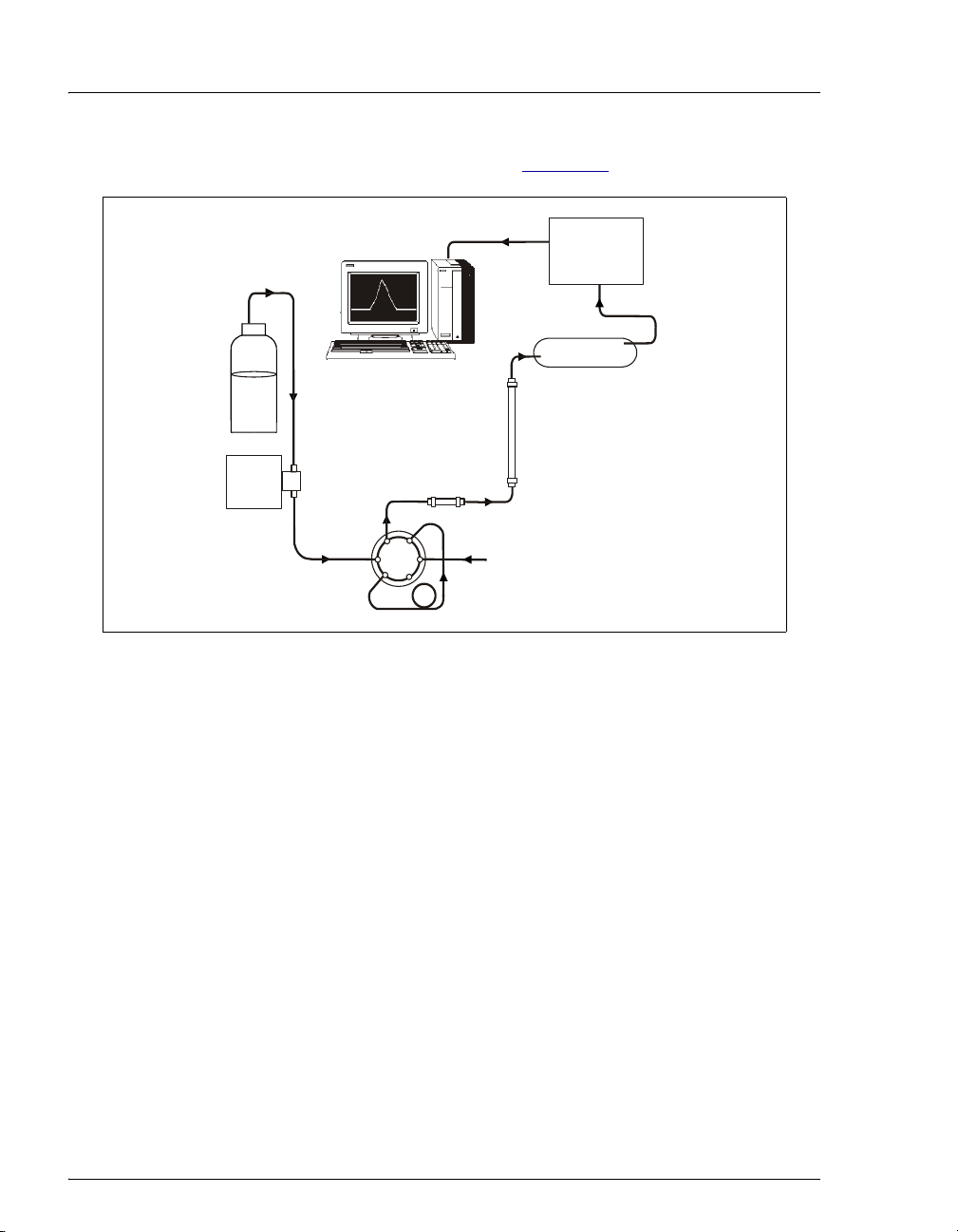
A typical IC analysis consists of 6 stages (see Figure 1-1).
1. Eluent Delivery
•Eluent, a liquid that helps to separate the sample ions, carries the
sample through the ion chromatography system. The ICS-1000 is an
isocratic delivery system. This means that the eluent composition and
concentration remain constant throughout the run.
2. Sample Injection
•The liquid sample is loaded into a sample loop either manually or
automatically (if an automated sampler is installed). When triggered,
the ICS-1000 injects the sample into the eluent stream.
•The pump pushes the eluent and sample through the guard and
separator columns (chemically-inert tubes packed with a polymeric
resin). The guard column removes contaminants that might poison the
separator column.
Figure 1-1. Ion Analysis Process
Guard Column
Separator
Column
Pump
Conductivity
Cell
Injection
Valve
Suppressor
1. Eluent
Delivery
3. Separation
5. Detectio
n
6
. Data Analysis
Sample Loop
Sample
Eluent
4. Suppression
2. Sample
Injection

1 • Introduction
Doc. 031879-01 3/03 1-3
3. Separation
•As the eluent and sample are pumped through the separator column,
the sample ions are separated. In the ICS-1000, the mode of
separation is called ion exchange. This is based on the premise that
different sample ions migrate through the IC column at different rates,
depending upon their interactions with the ion exchange sites.
4. Suppression
•After the eluent and sample ions leave the column, they flow through
a suppressor that selectively enhances detection of the sample ions
while suppressing the conductivity of the eluent.
5. Detection
•A conductivity cell measures the electrical conductance of the sample
ions as they emerge from the suppressor and produces a signal based
on a chemical or physical property of the analyte.
6. Data Analysis
•The conductivity cell transmits the signal to a data collection system.
•The data collection system (for the ICS-1000, this is Chromeleon®)
identifies the ions based on retention time, and quantifies each analyte
by integrating the peak area or peak height. The data is quantitated by
comparing the sample peaks in a chromatogram to those produced
from a standard solution. The results are displayed as a chromatogram
and the concentrations of ionic analytes can be automatically
determined and tabulated.

ICS-1000 Ion Chromatography System
1-4 Doc. 031879-01 3/03
1.2 Overview of the ICS-1000
The ICS-1000 is an integrated ion chromatography system containing a pump,
injection valve, column heater, and conductivity detector. Other system
components, including a guard column, separator column, and suppressor vary,
depending on the analyses to be performed.
The ICS-1000 can optionally be configured with a column heater for temperature
control of the column.
ICS-1000 operation is controlled remotely by a personal computer running
Windows®2000 or Windows XP and Chromeleon software (version 6.5 SP2 or
later). Chromeleon also provides data acquisition and data processing functions.
For communication between the ICS-1000 and Chromeleon, the ICS-1000 is
connected to a USB (Universal Serial Bus) port on the computer or a USB hub.
For installation instructions, see Section B.5 and also refer to Installing the
Chromeleon IC System (Document No. 031883).

1 • Introduction
Doc. 031879-01 3/03 1-5
1.3 About This Manual
Chapter 1
Introduction Introduces ion analysis and the ICS-1000; explains the
conventions used in this manual, including safety-related
information.
Chapter 2
Features
Overview
Provides an overview of ICS-1000 operating features and
system components; introduces the Chromeleon user
interface.
Chapter 3
Operation and
Maintenance
Provides operating instructions and describes routine
preventive maintenance procedures.
Chapter 4
Troubleshooting Lists problems and presents step-by-step procedures for
how to isolate and eliminate the cause of each problem.
Chapter 5
Service Provides step-by-step instructions for routine service and
parts replacement procedures that the user can perform.
Appendix A
Specifications Lists the ICS-1000 specifications and installation site
requirements.
Appendix B
Installation Describes how to install the ICS-1000.
Appendix C
TTL and Relay
Control
Describes the ICS-1000 TTL and relay control features.
Appendix D
Reordering
Information
Lists spare parts for the ICS-1000.
Appendix E
FAQ Provides answers to frequently asked questions about
ICS-1000 operation.
Appendix F
Glossary Defines terms commonly used in ion analysis.
ICS-1000 Ion Chromatography System
1-6 Doc. 031879-01 3/03
1.3.1 Safety Messages and Notes
This manual contains warnings and precautionary statements that can
prevent personal injury and/or damage to the ICS-1000 when properly
followed. Safety messages appear in bold type and are accompanied by
icons, as shown below.
Messages d'avertissement en français
Indicates an imminently hazardous situation which, if not avoided, will
result in death or serious injury.
Indicates a potentially hazardous situation which, if not avoided,
could result in death or serious injury.
Indicates a potentially hazardous situation which, if not avoided, may
result in minor or moderate injury. Also used to identify a situation or
practice that may seriously damage the instrument, but will not cause
injury.
Indicates that the function or process of the instrument may be
impaired. Operation does not constitute a hazard.
Signale une situation de danger immédiat qui, si elle n'est pas évitée,
entraînera des blessures graves à mortelles.
Signale une situation de danger potentiel qui, si elle n'est pas évitée,
pourrait entraîner des blessures graves à mortelles.
Signale une situation de danger potentiel qui, si elle n'est pas évitée,
pourrait entraîner des blessures mineures à modérées. Également
utilisé pour signaler une situation ou une pratique qui pourrait
gravement endommager l'instrument mais qui n'entraînera pas de
blessures.

1 • Introduction
Doc. 031879-01 3/03 1-7
Warnhinweise in Deutsch
Notes
Informational messages also appear throughout this manual. These are
labeled NOTE and are in bold type:
NOTE NOTES call attention to certain information. They alert
you to an unexpected result of an action, suggest how to
optimize instrument performance, etc.
Bedeutet unmittelbare Gefahr. Mißachtung kann zum Tod oder
schwerwiegenden Verletzungen führen.
Bedeutet eine mögliche Gefährdung. Mißachtung kann zum Tod oder
schwerwiegenden Verletzungen führen.
Bedeutet eine mögliche Gefährdung. Mißachtung kann zu kleineren
oder mittelschweren Verletzungen führen. Wird auch verwendet, wenn
eine Situation zu schweren Schäden am Gerät führen kann, jedoch
keine Verletzungsgefahr besteht.

ICS-1000 Ion Chromatography System
1-8 Doc. 031879-01 3/03
1.3.2 Safety Labels
The ICS-1000 meets EN 61010-1:1993 (safety), CAN/CSA-C22.2 No.
1010.1-92 (safety), UL 3101-1/10.93 (safety), EN 50082-1:1992
(susceptibility), EN 55011:1991 (emissions). The TUV GS, C, US Mark
safety labels and the CE Mark label on the ICS-1000 attest to compliance
with these standards.
The symbols below appear on the ICS-1000 or on ICS-1000 labels.
Alternating current
Protective conductor terminal (earth ground)
Power supply is on
Power supply is off
Doc. 031879-01 3/03 2-1
2•Features
This chapter describes key ICS-1000 features and introduces the Chromeleon user
interface.
2.1 Operating Features
2.1.1 Front Panel
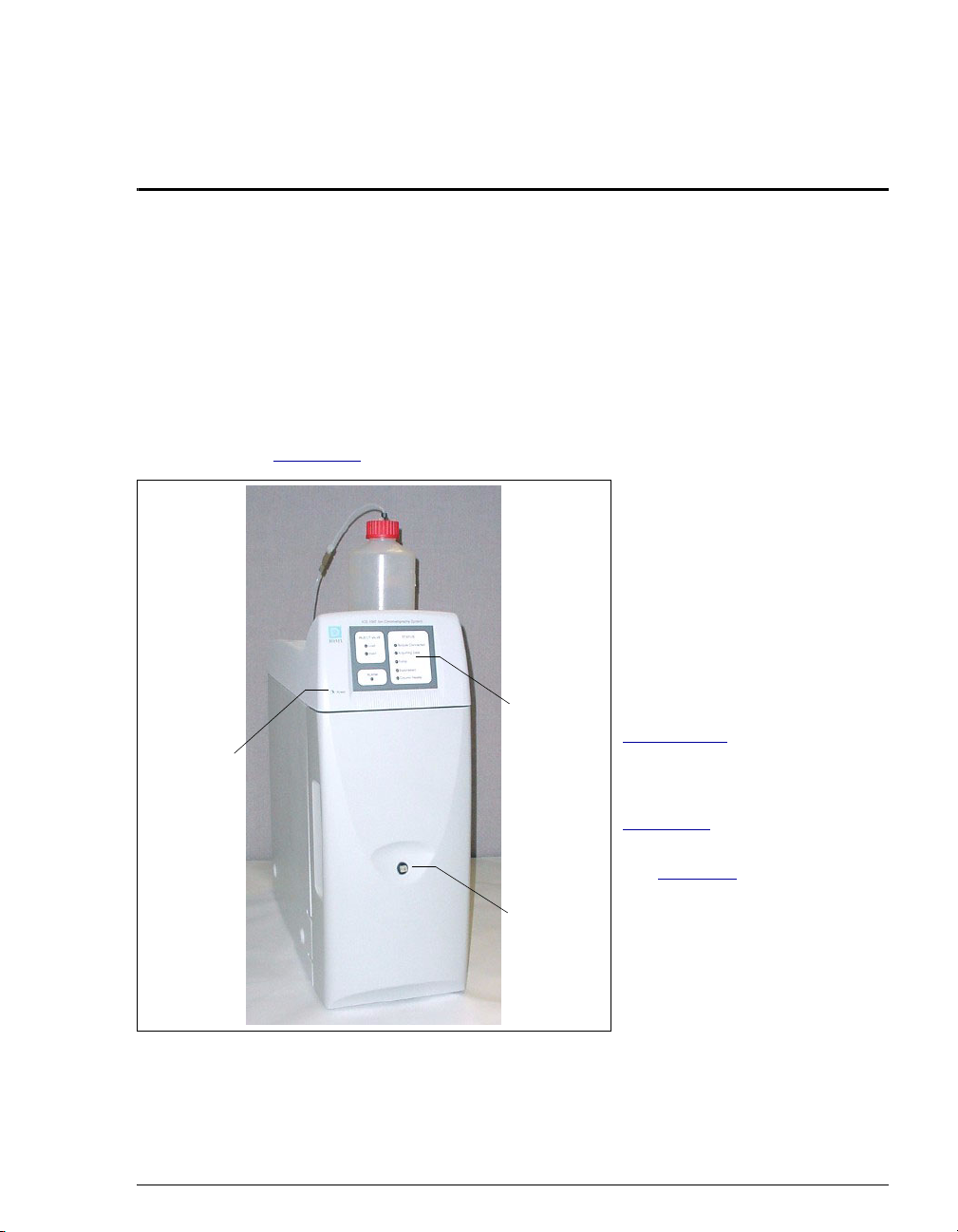
Figure 2-1 illustrates the front panel of the ICS-1000.
Injection Port
The sample to be analyzed can
be injected manually into the
injection port, using a syringe.
For automated sample
injection, the ICS-1000 must be
connected to an autosampler.
For more information about
sample injection, see
Section 3.10.
LEDs
The status LEDs (see
Figure 2-2) indicate the status
of various system functions.
See Table 2-1for a description
of each LEDs function. The
power LED indicates whether
the ICS-1000 power is on.
Figure 2-1. ICS-1000 Front Panel
Status
LEDs
Injection
Port
Power
LED
ICS-1000 Ion Chromatography System
2-2 Doc. 031879-01 3/03
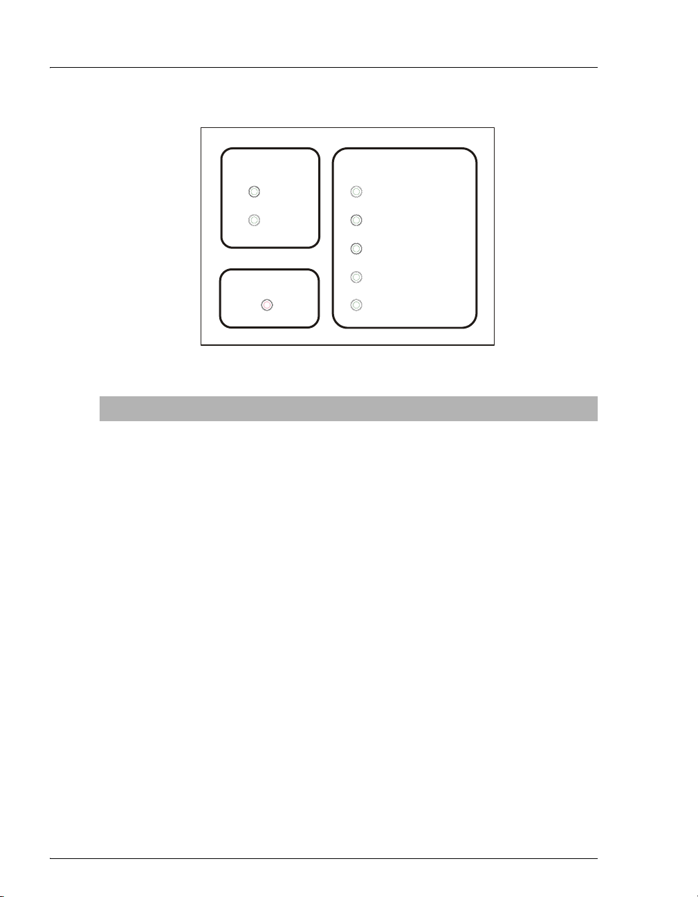
Figure 2-2. Status LEDs
LED Label If On (Green) If Flashing
Load Injection valve is in Load
position.
Valve error.
Inject Injection valve is in Inject
position.
Valve error.
Alarm No “on” (green) state. Error detected. Check the Chromeleon
Audit Trail for the cause.
Module
Connected
ICS-1000 is connected to
a Chromeleon timebase.
Does not flash.
Acquiring
Data
Sequence or manual data
acquisition is in progress.
Sequence has stopped due to an error.
Pump Pump is on. High or low pressure limit is exceeded.
The pump is turned off
Suppressor Suppressor is on and
current is being applied to
it.
Continuity check failed or suppressor is
over the voltage, current, or power limit.
The suppressor is turned off
Column
Heater
Column heater is at set
temperature.
Column heater is transitioning to a new
temperature.
Table 2-1. ICS-1000 Status LED States
ALARM
Inject
INJECT VALVE
Load
Column Heater
Acquiring Data
Suppressor
Pump
STATUS
Module Connected
Table of contents
Other Dionex Laboratory Equipment manuals

Dionex
Dionex P680 User manual

Dionex
Dionex UltiMate 3000 Series User manual

Dionex
Dionex IONPAC AG9-SC GUARD COLUMN User manual

Dionex
Dionex ICS-2100 User manual

Dionex
Dionex ICS-3000 User manual

Dionex
Dionex ICS-90 User manual

Dionex
Dionex UltiMate 3000 User guide

Dionex
Dionex TCC-100 User manual

Dionex
Dionex DX-120 User manual

Dionex
Dionex P680 User manual


