Dionex ICS-900 User manual

ICS-900 Ion Chromatography System
Operator’s Manual
Document No. 065215
Revision 02
September 2009

©2009 by Dionex Corporation
All rights reserved worldwide.
Printed in the United States of America.
This publication is protected by federal copyright law. No part of this publication
may be copied or distributed, transmitted, transcribed, stored in a retrieval system, or
transmitted into any human or computer language, in any form or by any means,
electronic, mechanical, magnetic, manual, or otherwise, or disclosed to third parties
without the express written permission of Dionex Corporation, 1228 Titan Way,
Sunnyvale, California 94088-3603 U.S.A.
DISCLAIMER OF WARRANTY AND LIMITED WARRANTY
THIS PUBLICATION IS PROVIDED “AS IS” WITHOUT WARRANTY OF
ANY KIND. DIONEX CORPORATION DOES NOT WARRANT,
GUARANTEE, OR MAKE ANY EXPRESS OR IMPLIED
REPRESENTATIONS REGARDING THE USE, OR THE RESULTS OF THE
USE, OF THIS PUBLICATION IN TERMS OF CORRECTNESS, ACCURACY,
RELIABILITY, CURRENTNESS, OR OTHERWISE. FURTHER, DIONEX
CORPORATION RESERVES THE RIGHT TO REVISE THIS PUBLICATION
AND TO MAKE CHANGES FROM TIME TO TIME IN THE CONTENT
HEREINOF WITHOUT OBLIGATION OF DIONEX CORPORATION TO
NOTIFY ANY PERSON OR ORGANIZATION OF SUCH REVISION OR
CHANGES.
TRADEMARKS
AES, AMMS, Chromeleon, CMMS, and SRS are registered trademarks of Dionex
Corporation. MMS, MicroMembrane, and OnGuard are trademarks of Dionex
Corporation.
Teflon and Tefzel are registered trademarks of E.I. du Pont de Nemours and
Company.
Microsoft, Windows 2000, and Windows XP are registered trademarks of Microsoft
Corporation.
PRINTING HISTORY
Revision 01, March 2008
Revision 02, September 2009

Doc. 065215-02 9/09 i
1 • Introduction. . . . . . . . . . . . . . . . . . . . . . . . . . . . . . . . . . . . . . . . . . . . . . 1
1.1 Overview of the ICS-900 . . . . . . . . . . . . . . . . . . . . . . . . . . . . . . . . . . . . . 1
1.2 The ICS-900 Operator’s Manual . . . . . . . . . . . . . . . . . . . . . . . . . . . . . . . 2
1.2.1 Overview . . . . . . . . . . . . . . . . . . . . . . . . . . . . . . . . . . . . . . . . . . 2
1.3 Safety and Regulatory Information . . . . . . . . . . . . . . . . . . . . . . . . . . . . . 3
1.3.1 Safety Messages and Notes . . . . . . . . . . . . . . . . . . . . . . . . . . . . 3
1.3.2 Safety Symbols . . . . . . . . . . . . . . . . . . . . . . . . . . . . . . . . . . . . . . 5
1.3.3 Declaration of Conformity . . . . . . . . . . . . . . . . . . . . . . . . . . . . . 6
2•Description. . . . . . . . . . . . . . . . . . . . . . . . . . . . . . . . . . . . . . . . . . . . . . . 7
2.1 Operating Features . . . . . . . . . . . . . . . . . . . . . . . . . . . . . . . . . . . . . . . . . . 7
2.1.1 Front Door and Top Cover . . . . . . . . . . . . . . . . . . . . . . . . . . . . . 7
2.1.2 Component Mounting Panel . . . . . . . . . . . . . . . . . . . . . . . . . . . . 9
2.1.3 Rear Panel . . . . . . . . . . . . . . . . . . . . . . . . . . . . . . . . . . . . . . . . . 11
2.2 Fluid Schematic . . . . . . . . . . . . . . . . . . . . . . . . . . . . . . . . . . . . . . . . . . . 14
2.3 System Component Details . . . . . . . . . . . . . . . . . . . . . . . . . . . . . . . . . . 16
2.3.1 Pump . . . . . . . . . . . . . . . . . . . . . . . . . . . . . . . . . . . . . . . . . . . . . 16
2.3.2 Pressure Transducer . . . . . . . . . . . . . . . . . . . . . . . . . . . . . . . . . 17
2.3.3 Injection Valve with Sample Loop . . . . . . . . . . . . . . . . . . . . . . 18
2.3.4 MMS 300 MicroMembrane Suppressor . . . . . . . . . . . . . . . . . . 19
2.3.5 Displacement Chemical Regeneration (DCR) . . . . . . . . . . . . . 20
Contents

ICS-900 Operator’s Manual
ii Doc. 065215-02 9/09
2.3.6 Conductivity Cell and DS5 Detection Stabilizer . . . . . . . . . . . .21
2.4 Chromeleon and Chromeleon Xpress Software . . . . . . . . . . . . . . . . . . .23
2.4.1 The Panel Tabset . . . . . . . . . . . . . . . . . . . . . . . . . . . . . . . . . . . .23
2.4.2 Software Control Modes . . . . . . . . . . . . . . . . . . . . . . . . . . . . . .24
2.4.3 System Wellness and Predictive Performance . . . . . . . . . . . . .25
3 • Operation and Maintenance . . . . . . . . . . . . . . . . . . . . . . . .27
3.1 Operation Overview . . . . . . . . . . . . . . . . . . . . . . . . . . . . . . . . . . . . . . . .27
3.2 Turning On the ICS-900 Power . . . . . . . . . . . . . . . . . . . . . . . . . . . . . . .28
3.3 Connecting to Chromeleon or Chromeleon Xpress . . . . . . . . . . . . . . . .28
3.4 Preparing the Eluent . . . . . . . . . . . . . . . . . . . . . . . . . . . . . . . . . . . . . . . .29
3.5 Preparing the Regenerant . . . . . . . . . . . . . . . . . . . . . . . . . . . . . . . . . . . .30
3.6 Priming the Pump . . . . . . . . . . . . . . . . . . . . . . . . . . . . . . . . . . . . . . . . . .32
3.7 Equilibrating the System . . . . . . . . . . . . . . . . . . . . . . . . . . . . . . . . . . . .35
3.8 Verifying Operational Status . . . . . . . . . . . . . . . . . . . . . . . . . . . . . . . . .35
3.9 Configuring Standby Mode . . . . . . . . . . . . . . . . . . . . . . . . . . . . . . . . . .36
3.10 Preparing Samples . . . . . . . . . . . . . . . . . . . . . . . . . . . . . . . . . . . . . . . . .37
3.10.1 Collecting and Storing . . . . . . . . . . . . . . . . . . . . . . . . . . . . . . . .37
3.10.2 Pretreating . . . . . . . . . . . . . . . . . . . . . . . . . . . . . . . . . . . . . . . . .37
3.10.3 Diluting . . . . . . . . . . . . . . . . . . . . . . . . . . . . . . . . . . . . . . . . . . .38
3.11 Processing Samples . . . . . . . . . . . . . . . . . . . . . . . . . . . . . . . . . . . . . . . .39
3.11.1 Overview . . . . . . . . . . . . . . . . . . . . . . . . . . . . . . . . . . . . . . . . . .39
3.11.2 Manually Processing Samples . . . . . . . . . . . . . . . . . . . . . . . . . .40
3.11.3 Automatically Processing Samples (Batch Processing) . . . . . .42

Contents
Doc. 065215-02 9/09 iii
3.11.4 Loading and Injecting Samples with an Autosampler . . . . . . . 44
3.11.5 Loading and Injecting Samples with a Syringe . . . . . . . . . . . . 46
3.11.6 Example Chromeleon Commands for Loading and
Injecting Samples . . . . . . . . . . . . . . . . . . . . . . . . . . . . . . . . . . . 48
3.12 Maintenance . . . . . . . . . . . . . . . . . . . . . . . . . . . . . . . . . . . . . . . . . . . . . 49
4 • Troubleshooting . . . . . . . . . . . . . . . . . . . . . . . . . . . . . . . . . . . . . . . 51
4.1 Alarms and Error Conditions . . . . . . . . . . . . . . . . . . . . . . . . . . . . . . . . . 51
4.2 Liquid Leaks . . . . . . . . . . . . . . . . . . . . . . . . . . . . . . . . . . . . . . . . . . . . . 57
4.3 Pump Difficult to Prime or Loses Prime . . . . . . . . . . . . . . . . . . . . . . . . 58
4.4 Pump Does Not Start . . . . . . . . . . . . . . . . . . . . . . . . . . . . . . . . . . . . . . . 59
4.5 No Flow . . . . . . . . . . . . . . . . . . . . . . . . . . . . . . . . . . . . . . . . . . . . . . . . . 59
4.6 Erratic Flow/Pressure Reading . . . . . . . . . . . . . . . . . . . . . . . . . . . . . . . 59
4.7 Excessive System Backpressure . . . . . . . . . . . . . . . . . . . . . . . . . . . . . . 60
4.8 Peak “Ghosting” . . . . . . . . . . . . . . . . . . . . . . . . . . . . . . . . . . . . . . . . . . 60
4.9 Nonreproducible Peak Height or Retention Time . . . . . . . . . . . . . . . . . 61
4.10 Abnormal Retention Time or Selectivity . . . . . . . . . . . . . . . . . . . . . . . 61
4.11 No Detector Response . . . . . . . . . . . . . . . . . . . . . . . . . . . . . . . . . . . . . . 62
4.12 High Detector Output . . . . . . . . . . . . . . . . . . . . . . . . . . . . . . . . . . . . . . 62
4.13 Baseline Noise or Drift . . . . . . . . . . . . . . . . . . . . . . . . . . . . . . . . . . . . . 63
5•Service. . . . . . . . . . . . . . . . . . . . . . . . . . . . . . . . . . . . . . . . . . . . . . . . . . . . 65
5.1 Diagnostics and Calibrations . . . . . . . . . . . . . . . . . . . . . . . . . . . . . . . . . 65
5.1.1 Opening the Wellness Panel . . . . . . . . . . . . . . . . . . . . . . . . . . . 65

ICS-900 Operator’s Manual
iv Doc. 065215-02 9/09
5.1.2 Wellness Panel Features . . . . . . . . . . . . . . . . . . . . . . . . . . . . . .67
5.1.3 Calibrating the Pressure Transducer . . . . . . . . . . . . . . . . . . . . .69
5.1.4 Calibrating the Cell . . . . . . . . . . . . . . . . . . . . . . . . . . . . . . . . . .70
5.1.5 Calibrating the Flow Rate . . . . . . . . . . . . . . . . . . . . . . . . . . . . .72
5.2 Replacing Tubing and Fittings . . . . . . . . . . . . . . . . . . . . . . . . . . . . . . . .73
5.3 Isolating a Restriction in the Liquid Plumbing . . . . . . . . . . . . . . . . . . . .74
5.4 Cleaning Eluent Bottles . . . . . . . . . . . . . . . . . . . . . . . . . . . . . . . . . . . . .76
5.5 Changing the Sample Loop . . . . . . . . . . . . . . . . . . . . . . . . . . . . . . . . . .76
5.6 Cleaning and Replacing Pump Check Valves . . . . . . . . . . . . . . . . . . . .77
5.7 Replacing a Pump Piston Seal and Backup Seal . . . . . . . . . . . . . . . . . .80
5.8 Replacing a Pump Piston . . . . . . . . . . . . . . . . . . . . . . . . . . . . . . . . . . . .86
5.9 Replacing the Waste Valve Seal . . . . . . . . . . . . . . . . . . . . . . . . . . . . . . .87
5.10 Rebuilding the Injection Valve . . . . . . . . . . . . . . . . . . . . . . . . . . . . . . . .88
5.11 Replacing the Conductivity Cell . . . . . . . . . . . . . . . . . . . . . . . . . . . . . . .90
5.12 Replacing the Suppressor . . . . . . . . . . . . . . . . . . . . . . . . . . . . . . . . . . . .91
5.13 Changing the Main Power Fuses . . . . . . . . . . . . . . . . . . . . . . . . . . . . . .92
A • Specifications . . . . . . . . . . . . . . . . . . . . . . . . . . . . . . . . . . . . . . . . . .93
A.1 Electrical . . . . . . . . . . . . . . . . . . . . . . . . . . . . . . . . . . . . . . . . . . . . . . . . .93
A.2 Physical . . . . . . . . . . . . . . . . . . . . . . . . . . . . . . . . . . . . . . . . . . . . . . . . . .93
A.3 Environmental . . . . . . . . . . . . . . . . . . . . . . . . . . . . . . . . . . . . . . . . . . . .93
A.4 Front and Rear Panel LEDs . . . . . . . . . . . . . . . . . . . . . . . . . . . . . . . . . .94
A.5 Pump . . . . . . . . . . . . . . . . . . . . . . . . . . . . . . . . . . . . . . . . . . . . . . . . . . . .94
A.6 Injection Valve . . . . . . . . . . . . . . . . . . . . . . . . . . . . . . . . . . . . . . . . . . . .95

Contents
Doc. 065215-02 9/09 v
A.7 Suppressors . . . . . . . . . . . . . . . . . . . . . . . . . . . . . . . . . . . . . . . . . . . . . . 95
A.8 Column Heater/Thermostat . . . . . . . . . . . . . . . . . . . . . . . . . . . . . . . . . . 96
A.9 Conductivity Detector and Flow Cell . . . . . . . . . . . . . . . . . . . . . . . . . . 96
A.10 Autosampler . . . . . . . . . . . . . . . . . . . . . . . . . . . . . . . . . . . . . . . . . . . . . 97
A.11 System Software . . . . . . . . . . . . . . . . . . . . . . . . . . . . . . . . . . . . . . . . . . 98
B • Reordering Information . . . . . . . . . . . . . . . . . . . . . . . . . . . . . 99
C • TTL and Relay Control . . . . . . . . . . . . . . . . . . . . . . . . . . . . . 101
C.1 Connecting a TTL or Relay . . . . . . . . . . . . . . . . . . . . . . . . . . . . . . . . . 102
C.2 Selecting TTL Input Control Modes and Functions . . . . . . . . . . . . . . 103
C.3 Configuring Relay Output 1 or 2 to Respond to the Pump Flow . . . . 106
C.4 Controlling TTL and Relay Outputs . . . . . . . . . . . . . . . . . . . . . . . . . . 108
C.5 Controlling an AS40 Automated Sampler with a Relay . . . . . . . . . . . 110
D•FAQ. . . . . . . . . . . . . . . . . . . . . . . . . . . . . . . . . . . . . . . . . . . . . . . . . . . . . . 113
D.1 How do I connect to an autosampler? . . . . . . . . . . . . . . . . . . . . . . . . . 113
D.2 How often should I perform calibrations? . . . . . . . . . . . . . . . . . . . . . . 113
D.3 Why are the retention times moving? . . . . . . . . . . . . . . . . . . . . . . . . . 113
D.4 How do I adjust retention times? . . . . . . . . . . . . . . . . . . . . . . . . . . . . . 114
D.5 When should I remake standards? . . . . . . . . . . . . . . . . . . . . . . . . . . . . 114
D.6 When should I remake eluents? . . . . . . . . . . . . . . . . . . . . . . . . . . . . . . 114
D.7 How do I start Chromeleon or Chromeleon Xpress? . . . . . . . . . . . . . 114
D.8 How do I back up data? . . . . . . . . . . . . . . . . . . . . . . . . . . . . . . . . . . . . 114

ICS-900 Operator’s Manual
vi Doc. 065215-02 9/09
D.9 How do I delete data? . . . . . . . . . . . . . . . . . . . . . . . . . . . . . . . . . . . . . .114
D.10 How do I shut off the system? . . . . . . . . . . . . . . . . . . . . . . . . . . . . . . .115
D.11 How do I store columns? . . . . . . . . . . . . . . . . . . . . . . . . . . . . . . . . . . .115
D.12 How do I know when a column is dirty? . . . . . . . . . . . . . . . . . . . . . . .115
D.13 How do I clean a column? . . . . . . . . . . . . . . . . . . . . . . . . . . . . . . . . . .115
D.14 Why is the conductivity high? . . . . . . . . . . . . . . . . . . . . . . . . . . . . . . .115
E • Introduction to Ion Chromatography (IC) . . . . .117
F • Glossary. . . . . . . . . . . . . . . . . . . . . . . . . . . . . . . . . . . . . . . . . . . . . . . . .119
Index

Doc. 065215-02 9/09 1
1 • Introduction
1.1 Overview of the ICS-900
The Dionex ICS-900 Ion Chromatography System (ICS-900) performs isocratic
ion analyses using suppressed conductivity detection. The ICS-900 is an
integrated ion chromatography system consisting of a pump, an injection valve,
and a conductivity cell. Other system components (guard column, separator
column, and suppressor) are ordered separately.
The ICS-900 is controlled with a PC running Windows®XP or Windows®2000
and the Chromeleon®Chromatography Management System (version 6.8 SP4 or
later) or Chromeleon Xpress. The Chromeleon Chromatography Management
System provides complete instrument control, data acquisition, and data
management. Chromeleon Xpress provides real-time control and monitoring of
Dionex chromatography instruments, but does not include data management
capabilities.
For communication between the ICS-900 and the PC on which Chromeleon or
Chromeleon Xpress is installed, the ICS-900 must be connected to a USB
(Universal Serial Bus) port on the PC or a USB hub. For details, refer to the
ICS-900 Ion Chromatography System Installation Instructions (Document No.
065214). The manual is provided on the Dionex Reference Library CD-ROM
(P/N 053891) and in the ICS-900 Ship Kit (P/N 067768).
NOTE For an introduction to basic ion chromatography
concepts, see Appendix E.

ICS-900 Operator’s Manual
2Doc. 065215-02 9/09
1.2 The ICS-900 Operator’s Manual
1.2.1 Overview
The electronic version (i.e., PDF file) of the ICS-900 operator’s manual
contains numerous hypertext links that can take you to other locations
within the file. These links include:
•Table of contents entries
•Index entries
•Cross-references (underlined in blue) to sections, figures, tables, etc.
If you are not familiar with how to navigate PDF files, refer to the Help
system for Adobe® Acrobat® or Adobe Reader®for assistance.
Chapter 1
Introduction Introduces the ICS-900; explains the conventions
used in this manual, including safety-related
information.
Chapter 2
Description Describes ICS-900 operating features, the
chromatographic flow path, and the software
required for ICS-900 control.
Chapter 3
Operation and
Maintenance
Provides operating instructions for the ICS-900
and describes routine preventive maintenance
procedures.
Chapter 4
Troubleshooting Lists problems and presents step-by-step
procedures for how to isolate and eliminate the
cause of each problem.
Chapter 5
Service Provides step-by-step instructions for routine
service and parts replacement procedures that the
user can perform.
Appendix A
Specifications Provides specifications and installation site
requirements for the ICS-900.
Appendix B
Reordering
Information
Lists spare parts for the ICS-900.

1 • Introduction
Doc. 065215-02 9/09 3
1.3 Safety and Regulatory Information
The ICS-900 was manufactured by Dionex Corporation at the following location:
527 Lakeside Drive, Sunnyvale, CA 94088-3603 U.S.A. The ICS-900 is designed
for IC (ion chromatography) applications and should not be used for any other
purpose. Operation of an ICS-900 in a manner not specified by Dionex may result
in personal injury.
If there are questions regarding appropriate usage, contact Dionex Technical
Support. In the U.S., call 1-800-346-6390. Outside the U.S., call the nearest
Dionex office.
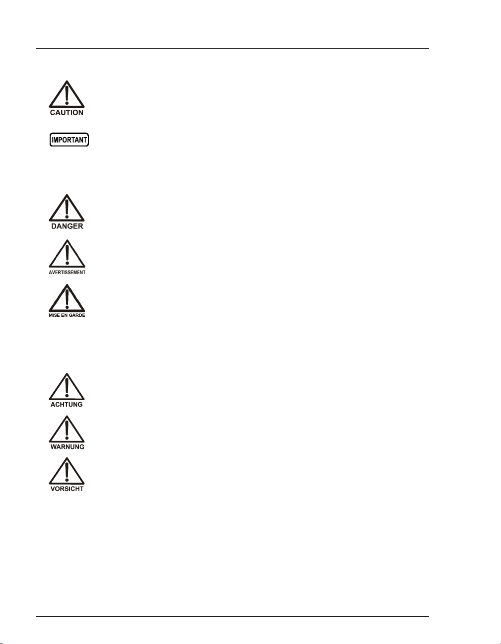
1.3.1 Safety Messages and Notes
This manual contains warnings and precautionary statements that can
prevent personal injury and/or damage to the ICS-900 when properly
followed. Safety messages appear in bold type and are accompanied by
icons, as shown below.
Appendix C
TTL and Relay
Control
Describes the ICS-900 TTL and relay control
features.
Appendix D
FAQ Provides answers to frequently asked questions
about ICS-900 operation.
Appendix E
Introduction to Ion
Chromatography
Describes basic ion chromatography concepts.
Appendix F
Glossary
Provides definitions of terms commonly used in
ion chromatography.
Indicates an imminently hazardous situation which, if not avoided, will
result in death or serious injury.
Indicates a potentially hazardous situation which, if not avoided,
could result in death or serious injury.
ICS-900 Operator’s Manual
4Doc. 065215-02 9/09
Messages d'avertissement en français
Warnhinweise in Deutsch
Indicates a potentially hazardous situation which, if not avoided, may
result in minor or moderate injury. Also used to identify a situation or
practice that may seriously damage the instrument, but will not cause
injury.
Indicates that the function or process of the instrument may be
impaired. Operation does not constitute a hazard.
Signale une situation de danger immédiat qui, si elle n'est pas évitée,
entraînera des blessures graves à mortelles.
Signale une situation de danger potentiel qui, si elle n'est pas évitée,
pourrait entraîner des blessures graves à mortelles.
Signale une situation de danger potentiel qui, si elle n'est pas évitée,
pourrait entraîner des blessures mineures à modérées. Également
utilisé pour signaler une situation ou une pratique qui pourrait
gravement endommager l'instrument mais qui n'entraînera pas de
blessures.
Bedeutet unmittelbare Gefahr. Mißachtung kann zum Tod oder
schwerwiegenden Verletzungen führen.
Bedeutet eine mögliche Gefährdung. Mißachtung kann zum Tod oder
schwerwiegenden Verletzungen führen.
Bedeutet eine mögliche Gefährdung. Mißachtung kann zu kleineren
oder mittelschweren Verletzungen führen. Wird auch verwendet, wenn
eine Situation zu schweren Schäden am Gerät führen kann, jedoch
keine Verletzungsgefahr besteht.
1 • Introduction
Doc. 065215-02 9/09 5
Notes
Informational messages also appear throughout this manual. These are
labeled NOTE and are in bold type:
NOTE NOTES call attention to certain information. They
alert you to an unexpected result of an action,
suggest how to optimize instrument performance,
etc.
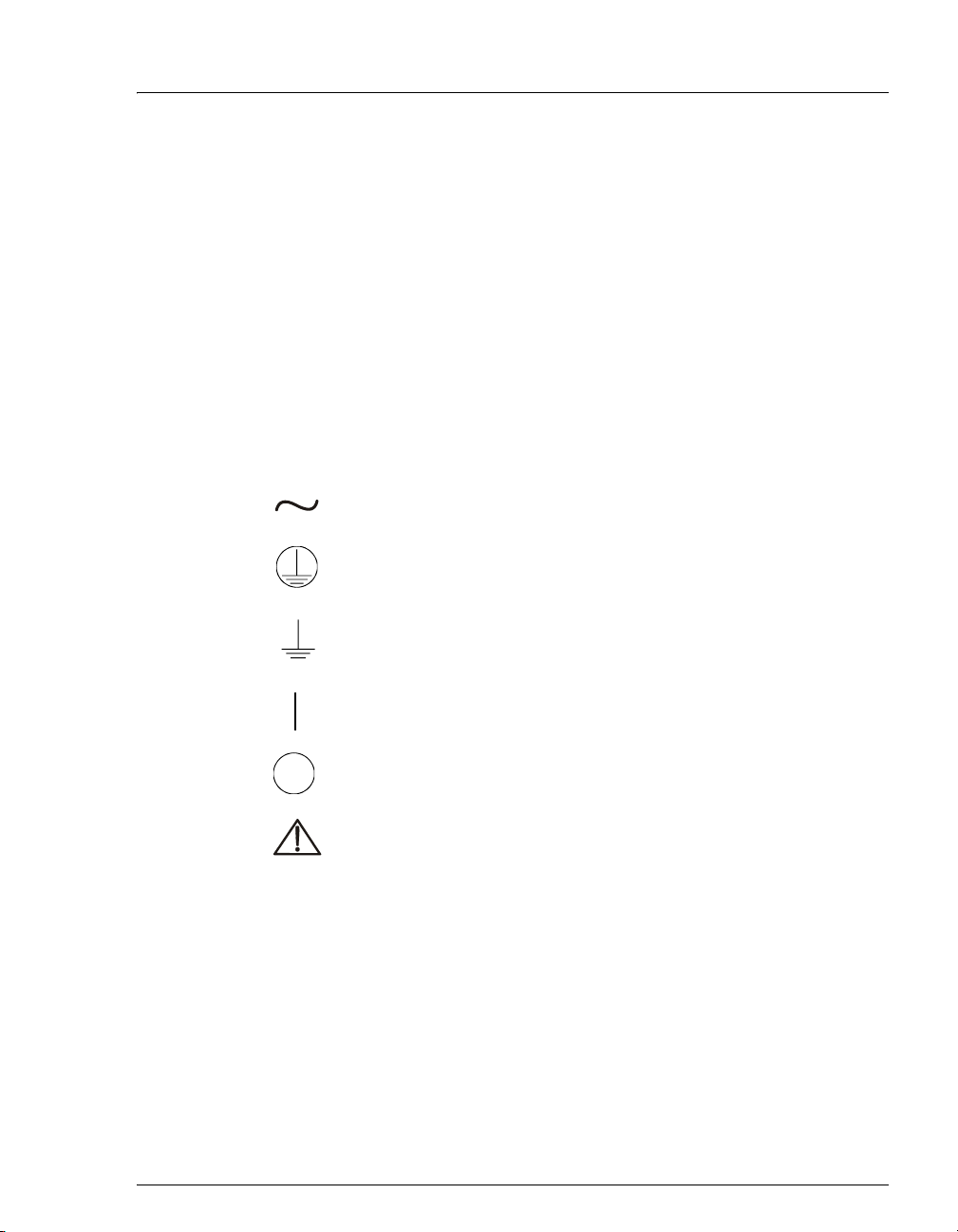
1.3.2 Safety Symbols
These symbols appear on the ICS-900 or on ICS-900 labels:
Alternating current
Primary protective conductor terminal
Secondary protective conductor terminal
Power supply is on
Power supply is off
Indicates a potential hazard. Refer to this operator’s
manual for an explanation of the hazard and how to
proceed.

ICS-900 Operator’s Manual
6Doc. 065215-02 9/09
1.3.3 Declaration of Conformity
The cETLus and CE marks on the ICS-900 model/data label indicate that
the ICS-900 is in compliance with the following standards.


ICS-900 Operator’s Manual
8Doc. 065215-02 9/09
LEDs
Three status LEDs (described below) are on the ICS-900 front door.
Other status information and alarm messages are displayed in the Audit
Trail in Chromeleon or Chromeleon Xpress. For a description of these
messages, see Section 4.1
Injection Port
The injection port can be connected to the injection valve inside the
ICS-900. The sample to be analyzed is injected into the injection port
using a syringe. For automated sample injections, the ICS-900 injection
valve can be connected to an autosampler, instead of to the injection port.
For more information about sample injection, see Section 3.11.5.
Eluent and Regenerant Bottles
The ICS-900 top cover is molded to hold one eluent bottle assembly
(P/N 062510) and one regenerant bottle assembly (anion, P/N 068222;
cation, P/N 068223).
•Eluent carries the sample through the ICS-900 and facilitates the ion
separation process. The type of eluent used depends on the analyses
LED Label If On (Green) If Flashing
Power ICS-900 power is on Does not flash
Ready System check passed, but
sequence not yet started
(LED stays on until run starts
or sequence is aborted)
System check failed (occurs if
system check executes for
10 minutes without success)
Run Running/acquiring data Error/alarm/fault (including
injection valve position)

2 • Description
Doc. 065215-02 9/09 9
performed. For example, an ICS-900 configured for anion analyses
uses carbonate eluent, while an ICS-900 configured for cation
analyses uses methanesulfonic acid (MSA) eluent.
•Regenerant renews the suppressor’s ability to suppress eluent
conductivity. An ICS-900 configured for anion analyses uses dilute
sulfuric acid regenerant. An ICS-900 configured for cation analyses
uses tetrabutylammonium hydroxide (TBAOH) regenerant. For more
information about suppressor regeneration, see Section 2.3.5.
2.1.2 Component Mounting Panel
Figure 2-2 shows the components installed on the component panel
behind the ICS-900 front door.
Figure 2-2. ICS-900 Component Mounting Panel
MMS 300
Suppressor
Injection Valve
Pressure
Transducer
Pump Heads
1
2
3
4
5
6
7
8
Separator Column
Guard Column
Tubing Chase
Conductivity Cell
(Housed in DS5
Detection Stabilize
r
1
2
5
46
7
3
8
9Backpressure
Tubing
9

ICS-900 Operator’s Manual
10 Doc. 065215-02 9/09
Conductivity Cell
The flow-through heated conductivity cell measures the electrical
conductance of analyte ions as they pass through the cell. A heat
exchanger inside the cell regulates the temperature to 40 °C (104 °F). The
cell is housed inside a DS5 Detection Stabilizer (P/N 067761). For details
about the conductivity cell and DS5 Detection Stabilizer, see
Section 2.3.1.
MMS™ 300 MicroMembrane Suppressor
The MMS 300 suppressor reduces the eluent conductivity and enhances
the conductivity of the sample ions, thereby increasing detection
sensitivity. For details about the MMS 300 suppressor, see Section 2.3.4.
Separator and Guard Columns
Both the separator and guard columns are packed with resin and perform
the separation of the sample ions. The main function of the guard column
is to trap contaminants and remove particulates that might damage the
separator column.
Pressure Transducer
The pressure transducer measures the system backpressure. See
Section 2.3.2 for details about the pressure transducer.
Pump Heads
The ICS-900 includes a dual-piston serial pump. The flow rate can be set
from 0.01 mL/min to 5.00 mL/min. However, for optimum performance,
set the flow rate to between 0.20 and 3.00 mL/min. Setting the flow rate
to 0.00 mL/min turns off the pump. For details about the pump, see
Section 2.3.1.
Injection Valve
The injection valve is a six-port, electrically-activated valve. For details
about the injection valve, see Section 2.3.3.
2 • Description
Doc. 065215-02 9/09 11
Tubing Chase
The tubing chase routes tubing from the component panel, through the
ICS-900 interior, to the rear panel.
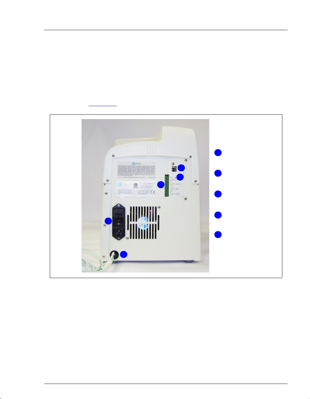
2.1.3 Rear Panel
Figure 2-3 illustrates the ICS-900 rear panel.
USB Connector
The USB connector connects the ICS-900 to the PC on which
Chromeleon or Chromeleon Xpress is installed. For the standard system
configuration of one ICS-900 connected to a PC, connect a USB cable
between the USB connector on the ICS-900 and a USB port on the PC.
For detailed connection instructions, refer to the ICS-900 Ion
Chromatography System Installation Instructions (Document
Figure 2-3. ICS-900 Rear Panel
Link LED
Fuse Holder,
Power Switch, and
Power Receptacle
Plumbing and
Waste Lines
1
2
3
4
5
TTL and Relay
Connector
USB Connector
1
2
3
4
5

ICS-900 Operator’s Manual
12 Doc. 065215-02 9/09
No. 065214), provided on the Dionex Reference Library CD-ROM
(P/N 053891) and in the ICS-900 Ship Kit (P/N 067768).
Link LED
The Link LED indicates the communication status
between the ICS-900 and the PC on which
Chromeleon or Chromeleon Xpress is installed.
TTL and Relay Connector
The TTL and Relay connector strip provides two TTL outputs, two relay
outputs, and four TTL inputs. The outputs can be used to control
functions in other TTL- or relay-controllable devices. The inputs can be
used to switch the injection valve position, turn the pump on and off, and
perform an autozero command. For connection instructions, see
Appendix C.
Fuse Holder, Power Switch, and Power Receptacle
•The fuse holder contains two fast-blow IEC 127 fuses rated 3.15 A
(P/N 954745). For instructions on how to change the fuses, see
Section 5.13.
•The power switch provides on/off control of power to the ICS-900.
•The power cord plugs into the IEC 320 three-prong receptacle.
LED Status Description
On The ICS-900 and the PC are linked, but no data is currently
being transmitted or received
Flashing The ICS-900 and the PC are linked and data is being
transmitted
Off The ICS-900 and the PC are not currently linked
The power supply cord is used as the main disconnect device. Make
sure the socket-outlet is located near the ICS-900 and is easily
accessible.
Le cordon d'alimentation principal est utilisé comme dispositif
principal de débranchement. Veillez à ce que la prise de base soit
située/installée près du module et facilement accessible.
Link
Table of contents
Other Dionex Laboratory Equipment manuals

Dionex
Dionex UltiMate 3000 User guide

Dionex
Dionex ICS-1000 User manual

Dionex
Dionex ICS-2100 User manual

Dionex
Dionex ICS-3000 User manual

Dionex
Dionex IONPAC AG9-SC GUARD COLUMN User manual

Dionex
Dionex As User manual

Dionex
Dionex ICS-90 User manual

Dionex
Dionex P680 User manual

Dionex
Dionex MSQ User manual

Dionex
Dionex TCC-100 User manual

Dionex
Dionex ICS-90 User manual

Dionex
Dionex DX-120 User manual

Dionex
Dionex RF-2000 User manual

Dionex
Dionex ProPac WCX-10 Assembly instructions

Dionex
Dionex P680 User manual

Dionex
Dionex UltiMate 3000 User guide

Dionex
Dionex AS-HV User manual

Dionex
Dionex UltiMate 3000 Series User manual

Dionex
Dionex P680 User manual


