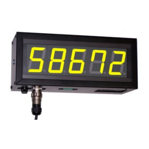
Ditel DMR21 F Series User manual

DMR21xF
DISPLAY CONFIGURATION
Once the device is powered on, it goes directly to indicate the internal software version and then sequentially
the data to be displayed that have been selected (current time HH:MM, date DD-MM and temperature in ºC).
Fully configurable and controllable via PC and USB cable with the MP Tools software (available on our
website) and access to the configuration of the main parameters via infrared control (optional). It is possible,
from a weekly calendar, to set up to two time slots for switching on and off per day
It is possible as an option to mount, among others, a relay output module with 12 configurable alarms in
clock mode and up to 15 presets in chronometer mode, a GPS module for time synchronization, a module for
Ethernet TCP/IP or WiFi communication and SNTP synchronization. , etc.
CONFIGURATION AND CONTROL FROM THE IR REMOTE CONTROL:
Menu key: Main key used to access the configuration menu. Register number appears on flashing mode on
the left and the character "A" on the right.
Keys "" , "": To go to the next register or to change the value of the selected register.
Keys "+V" , "-V": To increase or decrease the luminosity without entering on configuration menu.
Tecla "OK": To validate changes. A new press shows "ST ?" and a following confirms to save the changes
made. For the registers related to the clock (1 to 5) and chronometer (47 to 55), the menu is not exited until
the configuration sequence of the same has been completed. Register settings are not lost when power is
removed from the equipment.
Keys "Exit": To exit the menu without saving the changes. Also to return to clock mode from chornometer
mode.
Keys "": Quick access to clock registers.
Keys "⚫": Switches from clock mode to chronometer mode.
Keys " ": Displays alternately with each press 'hour:minutes' or 'minutes:seconds'.
TABLE OF MENU REGISTERS FOR IR REMOTE CONTROL:
QUICK INSTALLATION GUIDE: CLOCK, CALENDAR AND CHRONOMETER
REG. Value Description REG. Value Description
0- Test display 34 - Shows the software version
10 a 99 Set the year 35 1 a 99 DTP address. Device identification number (ID)
21 a 12 Set the month 36 - % of luminosity captured by the sensor
31 a 31 Set the day 37 - % of instantaneous luminosity delivered by the sensor
40 a 23 Set the hour 38 - Shows the internal temperature of the equipment
50 a 59 Set the minutes 39 - Shows outside temperature
60 a 99 Brightness level (0:Auto; 1 to 99: Manual) 40 - Shows the number of synchronized satellites (Only for GPS)
71 a 99 Minimum brightness (% of light defined for sensor) 41 - Maximum temperature value reached inside the equipment
81 a 99 Maximum brightness threshold (%) defined for sensor 45 0 / 1 Shows clock-calendar or clock-calendar+chronometer (0=clock-
calendar/1=clock-calendar+chronometer)
91 a 99 Speed of change of LED brightness according to external light 46 0 a 2 Chronometer work mode. 0=Up; 1=Down; 2=Up with final time
10 0 / 1 Enable alternative lighting that activates during set hours 47 0 a 23 (default time 1) Preset time 1 (asc./desc. chrono) (hours)
11 1 a 99 Alternative luminosity percentage 48/49 0 a 59 Preset time 1 (up/down chrono) (minutes and seconds)
12 0 a 23 Alternative brightness start time 50 0 a 23 Preset time 2 (down chrono) (hours)
13 0 / 1 Alternative brightness end time 51/52 0 a 59 Preset time 2 (down chrono) (minutes and seconds)
14 0 / 1 Shows or not the time in clock-calendar mode (0=NO/1=YES) 53 0 a 23 Preset time 3 (down chrono) (hours)
15 0 / 1 Time format (0=24H/1=12H) 54/55 0 a 59 Preset time 3 (down chrono) (minutes and seconds)
16 0 / 1 Shows or not the date in clock-calendar mode (0=NO/1=YES) 62 0 a 12 Selection of clock alarm number (activate relay 1).
17 0 / 1 Shows or not the temperature in clock-calendar mode
(0=NO/1=YES) 63 0 / 1 Activate selected clock alarm (by default fixed from Monday to
Sunday).
19 4 a 99 Time in seconds that the clock-calendar-temp is displayed 64 0 a 23 Define selected clock alarm minutes.
20 0 a 7 0:Random; 1:Immediate; 2:Ascending; 3:Descending; 4:Upward
shutter; 5:Lower shutter; 6:Odometer; 7: Progressive brightness (7-
segment clock only: 0, 1 and 7) 65 0 a 59 Define selected clock alarm minutes
21 1 a 99 Effect speed (pixels/s) (Only for matrix clocks) 70 1 / 0 Shows battery level. (1=OK/0=Replace)
23 -12 a +14 Define difference from default time zone (GMT+1) 72 1 / 0 Device On/Off auto. (0=Disabled 1= Enabled)
24 0 / 1 Enable/disable automatic time change (0=NO/1=YES 73 a 76 0-23/59 Hour/minute auto power on. Hour/minute auto off.
33 9ºC Offset de temperatura. Suma o resta los grados indicados 99 - Reset to return to factory settings
Chronometer:
To work with the chronometer press the "⚫" key. To exit press the "Exit" key.
When chronometer stopped, press the "OK" key to start.
When chronometer running, press "OK" again to pause.
When chronometer running, press the "⚫" key to reset the time to 0 or to a predefined value for down mode.
On down mode, press the "⚫"key tochange between the three predefined times
Arrows
Exit
OK
Clock
menu
Menu
Hour:min
min:sec
Chronometer
Luminosity

26.11.20 30728505
DISEÑOS Y TECNOLOGÍA, S.A.
Xarol, 6B P.I. Les Guixeres
08915 Badalona (Barcelona) - España
Tel. +34 933 394 758
Fax +34 934 903 145
Email: dtl@ditel.es ; web: www.ditel.es
DIMENSIONS
MOUNTING
The displays are supplied by default with the power cable, the
remote control for its configuration (option), a mini USB cable, a
temperature probe, WiFi/GPS antenna (option). For its installation,
fix the brackets on the wall and hang the device
Rear view of the display with mounting brackets.
Access to
connectors
THE ADVANCED CONFIGURATION OF THE PARAMETERS OF THE
MODULES IS DONE THROUGH THE "MP Tools" APPLICATION
AVAILABLE ON OUR WEBSITE.
66mm
210mm
770mm
268mm
95mm
79mm
TECHNICAL SPECIFICATIONS
POWER SUPPLY AND FUSES
DMR21xF:..................... 88-264V AC 47/63Hz or 125-373V DC
Maximum consumption ................................................... 70VA
Recommended fuse ......................................................... T 5A
VISUALIZATION
Approx. max. reading dist............................................ 100m
LED type......................................................................... Oval
LED diameter............................................................... 5mm
Digit number ....................................................................... 4
Digit height ................................................................ 210mm
LED colors available ................. Amber, red, white, green, blue
.(by default Amber or red . for the rest consult minimum order )
Automatic brightness intensity control or by software (0-100%)
Viewing angle ............................... 70º horizontal, 35º vertical
Clock drift .......................................................... < 2min./year
SNTP sync period .................................................. 10 minutes
ENVIRONMENTAL CONDITIONS
Working temperature ............................................ -10ºC ÷ 50ºC
Relative humidity (non condensing) ..................... <90% @ 40ºC
Protection degree .............................................................. IP54
MATERIALS
Front.. ............................................... .transparent polycarbonate
Case...................................................................Black aluminium
Weight ................................................................................ 7kg
COMUNICATION
Ports ............................................................. Mini USB (default)
.................................................RS232/RS485, Ethernet (10/100)
......WiFi (availability depending on radio regulation of the country)
Protocols ............................................................... DTPM, SNTP
Transmission rate ................ 1200 to 115200 Baud (configurable)
Remote IR control range...........................max 10m (no sun lihgt)
TEMPERATURE PROBE
Accuracy (-15ºC ÷ 60Cº) ...............................................≤ ±1.5ºC
RELAY OUTPUTS
Type and máximum current ............................. SPDT, 8A/250Vac
Connection terminals can be directly
reached through rear right side of the
device as shown in figure above.
The instrument provides 1, 2, 3 or 4 rear
connectors depending on the option that it
is mounted. See figures. Connectors type
are: RJ45 (Ethernet), Mini-B (USB), RJ12
(RS232), Mini combicon (RS485/2 relay
outputs), SMA (GPS/WiFi anthena).
Cable alimentación implementado a través
de prensaestopa.
Terminals for RS485 and Digital inputs
connector admit cables with section from
0.14mm2 up to 1.5mm2 (AWG 28÷16).
*GPS OPTION: Install the supplied GPS
antenna in a place with good reception, to
allow the equipment to synchronize from
the signal received from at least 3
satellites.
GPS CON-
NECTOR
USB PORT
OPTIÓN /A: (GPS*)
USB PORT
ETHERNET
PORT
OPTION /NE:
(ETHERNET)
OPTIÓN /NW: (WiFi)
2 relay outputs
PIN 1 NC 1
PIN 2 COM. 1
PIN 3 NO 1
PIN 4 N.C.
PIN 5 N.C.
PIN 6 N.C.
6 5 4 3 2 1
2 RELAY OUTPUTS
Depending on
configurationeach relay
is activated by the
clock or the
chronometer.
RS 232
PIN 1 GND
PIN 2,3 N.C.
PIN 4 TxD
PIN 5 RxD
PIN 6 5V DC OUT
6...1
USB PORT
RS 485
PIN 1 B
PIN 2 NC
PIN 3 A
1 2 3
OPTION /X:
(RS232 / RS485)
CONNECTIONS
LED's WiFi STATUS:
Red: OFF (conected) / Blinking (no
conected, check WiFi settings).
Green:Blink slow(OK) /OFF (fault) /
Blink fast (configuration mode).
Amber:Data transmisión.
USB PORT
WiFi PORT
WARNING
Isolation:
3000Vrms for 1 minute to
input/output terminals
and power terminals
ALIMENTATION
88-264V AC
125-373V DC
70VA
Recommended
fuse: (5A)
IMPORTANT!
To guarantee electrical safety according to EN 61010-1 a protective
external fuse against overcurrents must be installed.
Directives EMC 2014/30/EU LVD 2014/35/EU
Standards EN 61326-1EN 61010-1
CE Conformity.
WARNING: If this instrument is not installed and used in
accordance with this instructions, the protection provided by it
against hazards may be impaired.
To meet the requirements of EN 61010-1 standard, where the unit is
permanently connected to main supply, its is obligatory to install a circuit
breaking device easy reachable to the operator and clearly marked as
the disconnecting device.
According to Directive 2012/19/EU, you cannot dispose of this
appliance as normal urban waste. You can return it, free of
charge, to the place where it was purchased so that controlled
treatment and recycling can be carried out.
Mounting
support Wall
support
Other Ditel Measuring Instrument manuals

Ditel
Ditel Kosmos series User manual

Ditel
Ditel KOSMOS JUNIOR-C User manual

Ditel
Ditel KOSMOS MICRA-D User manual

Ditel
Ditel KOSMOS ALPHA-C User manual

Ditel
Ditel KOSMOS MICRA-M User manual

Ditel
Ditel IDEAL-P User manual

Ditel
Ditel IORD1826 User manual

Ditel
Ditel KOSMOS PICA-F User manual

Ditel
Ditel JUNIOR JR-D User manual

Ditel
Ditel DINOS DT203/NE User manual

Ditel
Ditel IOX121LTH User manual

Ditel
Ditel DINOS DN Series User manual

Ditel
Ditel DN119/NN User manual

Ditel
Ditel Kosmos series User manual

Ditel
Ditel DN109/NN User manual

Ditel
Ditel KOSMOS ALPHA-P User manual

Ditel
Ditel KOSMOS PICA-T User manual

Ditel
Ditel JUNIOR JR-D User manual

Ditel
Ditel DN129/NN User manual

Ditel
Ditel DINOS DT Series User manual