dji Spreading WingsS800 EVO User manual

Spreading Wings S800 EVO
User Manual
V 1.06
2013.10.14 Revision
www.dji.com

Disclaimer
Thank you for purchasing this DJI product. Please regularly visit the S800 EVO web page at www.dji.com, which is
updated regularly. Product information, technical updates and manual corrections will be available on this web page.
Due to unforeseen changes or product upgrades, the information contained in the manual is subject to change
without notice.
Read this disclaimer carefully before using this product. By using this product, you hereby agree to this disclaimer
and signify that you have read them fully. Please strictly follow the manual to assemble and use the product. The
manufacturer and seller assume no liability for any resulting damage or injury arising from the operation or use of
this product.
DJI is registered trademark of DJI Innovations. Names of product, brand, etc., appearing in this manual are
trademarks or registered trademarks of their respective owner companies. This product and manual are copyrighted
by DJI Innovations with all rights reserved. No part of this product or manual shall be reproduced in any form
without the prior written consent or authorization of DJI Innovations. No patent liability is assumed with respect to
the use of the product or information contained herein.

Profile
S800 EVO is a multi-rotor designed for aerial photograph which integrates reinforced mechanical structures,
stabilized dynamical system and high-efficiency power supply. Integrated designs make assembly and configuration
become especially easy and fast; retractable landing gear, foldable propellers and collapsible GPS Mount are
conveniently portable for optimal user experiences. Retractable landing gears and vibration dampers coordinate to
create omnidirectional aerial view and high quality photograph. Combined with professional DJI multi-rotor
autopilot system S800 EVO will achieve hovering, cruising and other steady flight elements, which can be applied
for aerial photography and other aero-modeling activities.
460mm(Length)
425mm(Width)
320mm(Heigth)
155mm
(Top
Width)
350mm(Length)
240mm(Diameter)

Contents
Disclaimer................................................................................................................................................................................................................ 2
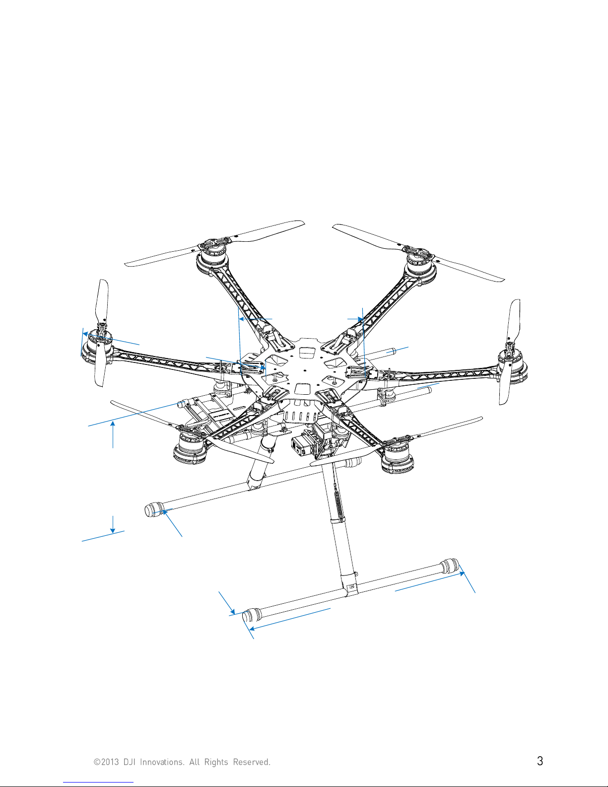
Profile....................................................................................................................................................................................................................... 3
Contents.................................................................................................................................................................................................................. 4
Product Usage Cautions ................................................................................................................................................................................... 5
In The Box............................................................................................................................................................................................................... 6
Tools Needed ........................................................................................................................................................................................................ 6
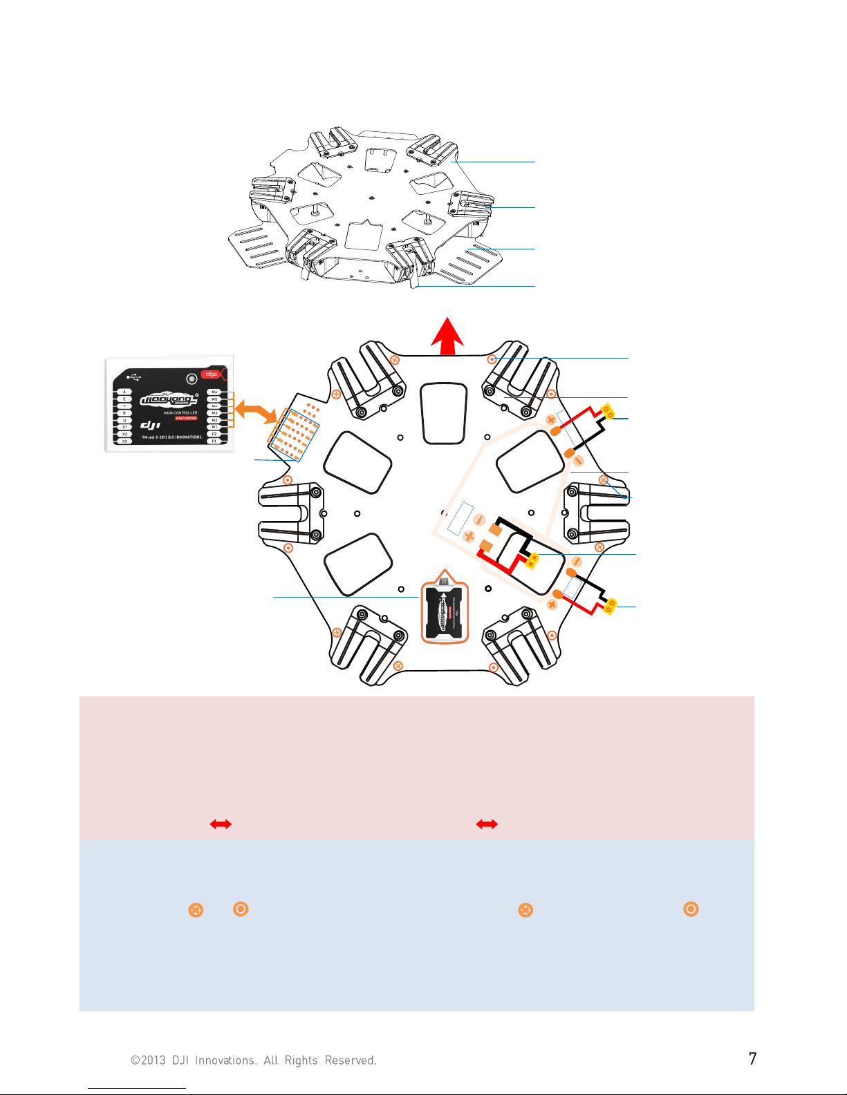
Center Frame Wiring ......................................................................................................................................................................................... 7
Attach Electric Equipment to Center Frame............................................................................................................................................. 8
Mount Frame Arms............................................................................................................................................................................................ 10
Mount Landing Gear..........................................................................................................................................................................................12
1 Assembly & Connection.......................................................................................................................................................................12
2 Travel Calibration..................................................................................................................................................................................13
3 Transmitter Setting...............................................................................................................................................................................14
4 Usage .........................................................................................................................................................................................................14
5 Mount Battery Bracket........................................................................................................................................................................16
Assembly ................................................................................................................................................................................................................17
Install the IMU Mount (Optional) ..................................................................................................................................................................18
Appendix................................................................................................................................................................................................................19
ESC Sound...................................................................................................................................................................................................19
ESC LED.......................................................................................................................................................................................................19
Specifications............................................................................................................................................................................................ 20
FAQ (Trouble Shooting)...................................................................................................................................................................................21
Solder ESC...................................................................................................................................................................................................21
Assemble the Vibration Absorber of Motors..................................................................................................................................21
Spare Parts Listing.............................................................................................................................................................................................22

Product Usage Cautions
When flying, the fast rotating propellers may cause serious damage(s) and injuries. Therefore, please fly with a high
safety in mind at all time.
Assembly Cautions
(1) Mount the GPS Module with a bracket, to avoid interference with the power board of center frame.
(2) For IMU mounting, make sure the arrow direction marking on the IMU is pointing to the aircraft nose.
(3) The receiver is strongly recommended to be attached under the bottom board of center frame, and the
head of antenna is downward without any obstacle. Otherwise the aircraft may be out of control, since
the wireless signal may be lost.
(4) Mount the arms correctly.
a) Center frame Arm
b) Center frame Arm
(5) For removing screws in the bottom board, please proceed with cautious, avoiding damages. Do not
remove any other screws fixed with glue.
(6) Notice matching the indications is very important, please pay attention to them.
Flight Cautions
(1) With DJI WKM autopilot system, make sure the output signal of WKM F1~F2 and M1~M6 are all normal,
to avoid serious damages and injuries.
(2) Keep flying the multi-rotor a distance from people, building, high-voltage lines, tall trees, water, etc.
(3) Make sure to use 6S LiPo battery for power supply.
(4) Do not get close to or touch the working motors and propellers, which will cause serious injury.
(5) Do not over load the multi-rotor.
(6) Make sure the propellers and the motors are installed correctly and firmly before flying.
(7) Make sure all parts of product are in good condition before each flight. Do not fly with wore or broken
parts.
(8) Strongly recommend you to use DJI parts as much as possible.
Others
(1) If you have any problem you cannot solve, please contact your dealer or DJI customer service.

In The Box
Center Frame×1
Frame Arm×6
Retracting Mechanism×2
Landing Gear Support Tube ×2
Base Pipe×2
H Frame Connection Pipe×1、Spring×2
Package of 3-PIN Servo Cable ×1
Silicone Rubber Damper ×4
Package of Battery Tray×1
Package of IMU Mount×1
GPS Fixed Seat×1
Screw Package for Frame×1
Screw Package for Landing Gear×1
Out of The Box Guidance ×2
Tools Needed
2.0mm Hex Wrench, 2.5mm Hex Wrench
For mounting screws.
Thread Locker
For fastening screws.
Nylon Cable Tie
For binding devices and wires.
Scissors
Diagonal Cutting Pliers
Foam Double Sided Adhesive Tape
For fixing receiver, controller and other modules.

Center Frame Wiring
The top board is a power distribution board, and the bottom board is for loading autopilot system components.
Top Board
Bottom Board
Buckle
Slot
M1
M2
M3
M4
M6
M5
BATT
PM
GIMBAL
IMU Front
Aircraft Nose
To Battery
To PMU
XT60 Male
XT60 Female
XT60 Female
To Gimbal
M1
M2
M3
M4
M5
M6
Motor clock-wise
ESC signal outlet
To main controller
Mark
IMU mount position
Circuit line
Parallel Circuit
Motor number
Mark
Motor counter clock-wise
Mark
Top Board
Notes:
(1) For IMU mounting, make sure the arrow direction marking on the IMU is pointing to the aircraft nose.
(2) Connect the 3-pin connectors (M1~M6) of servo cable from WKM M.C. to ESC signal socket (M1~M6) on
center frame markings accordingly.
(WKM M.C. M1 ESC signal socket M1, …… , WKM M.C. M6 ESC signal socket M6)
Tips:
(1) The main battery power leads, gimbal and PMU leads are on the bottom surface of the top board.
(2) Markings and stand for the propeller rotation direction. means clock-wise, and means
counter clock-wise.
(3) If other lead connector is required, please cut the original connector and solder on the new one. (But NOT
Recommend.)

Attach Electric Equipment to Center Frame
1. (Fig.1)Remove the screws in the bottom board.
2. (Fig.2)Attach the IMU module into IMU position in the center frame. Ensure the IMU casing is out of
touching the top board edge, as vibration can cause IMU mal-function.
3. (Fig.2)Please attach DJI Autopilot System parts onto the bottom board (not including GPS modules.
4. (Fig.2)Connect the Autopilot System and receiver. Please refer to DJI
WKM User Manual
for details.
5. (Fig.3)Please fix all the screws to bottom board, and use adequate thread locker.
6. (Fig.4)Attach the GPS Fixed Seat to the top board (near to the M3), then mount the GPS Module to the
GPS Fixed Seat with a bracket.
7. Configure Autopilot System. Please refer to DJI
WKM User Manual
.
Note:
(1) Make sure to mount the IMU module at the IMU position first, and the mount orientation is correct.
(2) Mount the GPS with a bracket, to avoid interference from center frame power board.
(3) Make sure the USB port of the M.C. is pointing outwards for easy access.
(4) Please wire neatly. Make sure the wires will not be cut by the edge of frames.
(5) Install the screws with appropriate strength to prevent damage threads.
(6) Watch out clamping fingers when folding the GPS Bracket.
To GIMBAL Lead
To the CAN Port of
GPS/Compass Module
You can attach the LED
Module to the support
tube.
Note: Risk of wire cut
off by the Retracting
Mechanism.
GPS/Compass
Module
Micro-USB
Port faces
outwards for
connection
convenience
Receiver
(D-BUS)You can wire the LED
through the bottom board
To PM Lead
Fig.1 Remove the screws Fig.2 Attach the Autopilot System

Fig.3 Fix the screws
Note: for DJI A2 user,
please use the
component in red; for
WKM user, it is not
required.
Fig.4 Mount the GPS Fixed Seat and GPS module
Mind You Fingers
Fig.5 Note of folding the GPS Bracket

©2012 DJI Innovations. All Rights Reserved. 10
Mount Frame Arms
Step 1
Step 2
Motor rotation direction
Clock-wise
Counter clock-wise
Motor
ESC
LED
Copper contacts
Screw
Propeller
Cover
(1)
Step 3
Step 4
Step 5
(2)
35o
Horizontal
Vertical
Horizontal
Step1: Check the arms.
(1) Make sure the copper contacts are in good condition without bend or severe wear.
(2) Make sure the propellers are without crack, and screws in propeller cover tight.
(3) Make sure the motors are mounted firmly, and rotate freely.
(4) We recommend you to mount the arms with red propeller cover to M1 and M2 to indicate the nose
of aircraft.
(5) Distinguish the marks and on the arms.
Arm Center frame
Arm Center frame
Step2: Insert the frame arm into center frame vertically.
Step3: Slowly rotate the frame arm upward until positioned completely.
Step4: Press down the buckle to lock the arm. Make sure the arm does not move.
Step5: Make sure the buckle is pressed down correctly, about 35o under normal circumstances.
Notes:
(1) Please add some lubricant at the position (1) if it is hard to press down the buckle.
(2) Slowly rotate the frame arm to prevent from breaking the copper contacts.

(3) Please refer to (2) to make sure the arm is perfectly positioned.
(4) Make sure to use appropriate strength to press down the buckle correctly.
(5) Do not hot plug arms.
Tips:
(1) LED is on after motor start.
Step 6 Double Check
Arms①②are aircraft nose, arms④⑤ are aircraft tail. See from top, motors on arms①③⑤ rotate counter
clockwise; motors on arms②④⑥ rotate clockwise.
Aircraft Nose
①
②
③
④
⑤
⑥

Mount Landing Gear
By using a 2-position switch of R/C transmitter, you can control the landing gear to retract remotely.
1 Assembly & Connection
The part with the control board attached is defined as left, and the other part is right. Make sure to make a
distinction between the left and the right servos.
RIN
L
Control Board
Servo
Arm
Center Line
Servo
Servo Arm Installation
Finished
Servo Assembly
Right art of the
anding ear
P
LG
Left Servo
Right Servo
Left Servo
Right Servo
SET Button
LED
Receiver Channel
ADircraft oseNirection
Left art of
the
P
LGanding ear
DANGER!!!
DO NOT TOUCH!
step1: Servo Installation
(If the servos have already been installed, please skip this step.)
1. (Shown in the Fig) Define and mark the two HS-7954SH servos from Hitec as left servo and right servo.
2. Connect the left servo to the [L] port on the control board, and the right servo to the [R] port.
3. Keep pressing the SET button with aid of a small tool, and then power on. You will see the yellow LED
beside SET button flashes quickly, and then wait until the servos have finished their position initialization.
4. Make sure the servo arm is parallel to the servo’s center line.
5. Power off, assemble the left and right servos to the left and the right parts of the landing gear.
Tips: If you use your own servos, it is recommended to use the dedicated programmer from Hitec to enlarge the
servo travel from 120° to 150°, and then install servos by the above steps. Servos from DJI have been enlarged
servo travel.
step2: Mechanical Assembly

1. Assemble the left and right parts respectively, and then fix the screws at the joints with appropriate
thread locker.
2. Connect the left and right parts with connecting rod.
3. For safety reasons, make sure to connect the springs to both parts.
step3: Electrical Connections
1. Plug the cables from the servos into the correct ports on the control board. Make sure the right servo is
connected to the [R] port, and the left servo to the [L] port.
2. Connect the required 2-position switch of R/C receiver to the [IN] port.
2Travel Calibration
If the Landing Gear you got has been installed with the servos, please skip this step. Otherwise, calibrate the system
using the following procedures.
1. For safety reasons, please keep your hands away from any link mechanism to avoid injury.
2. Make sure the [R], [L] and [IN] connections are correct and firmly connected.
3. Hang the Landing Gear in the air during calibration, as the landing gear will move.
4. Keep pressing the SET button using a small tool and power on. You can see the LED flashes YELLOW
quickly, and then press the SET button once again. The system begins auto calibration with the indication
of the LED flashing YELLOW slowly. DO NOT obstruct any moving part during auto calibration.
5. The left-part is calibrated, the left link mechanism first moves up then moves down automatically. Then
the right-part is calibrated, the right link mechanism first moves up then moves down automatically.
6. After calibration, both left and right parts are in the [Lower] position, and the LED is solid GREEN on.
Then the landing gear will work normally.
Notes:
(1) If the LED is solid YELLOW on during calibrating, it means that there is something wrong with the
calibration, please re-do the Servo Installation of the Assembly & Connection section, since the servo arm
might be installed with a wrong angle.
(2) Please avoid any obstruction during calibrating. If the landing gear is blocked from moving, please
recalibrate the landing gear by the above steps.
(3) If the [R] and [L] servo cables are reversed, the travel will not be measured correctly. Please connect
correctly and recalibrate the landing gear using the above steps.

3Transmitter Setting
Select a 2-position switch (default setting is OK) of
Transmitter as the control input of the landing gear, and
then make sure the corresponding port of receiver is
connected to the [IN] port on control board.
Fig. 1
Fig. 2
4 Usage
The landing gear can be used by following the steps below after assembly & connection.
1. Make sure the transmitter & receiver batteries are fully charged.
2. Toggle the switch to the [Lower] position, and then turn on the transmitter.
3. Make sure the [R], [L] and [IN] connections are correct and firmly connected.
4. Make sure the Landing Gear is at the [Lower] position, and then power on the system. If the green LED is
solid on, then this is a normal start. If the LED flashes GREEN slowly, please re-calibrate the system
according to the procedure of Travel Calibration.
5. Make sure to toggle the switch to the [Retracted] position ONLY AFTER you takeoff the aircraft.
6. When the aircraft is landing, please toggle the switch to the [Lower] position for a safe landing.
Retracted:Toggle the switch to
this position to retract the
landing gear (Fig.1)
Lower:Toggle the switch to this
position to lower the landing
gear (Fig. 2)
Tips:
(1) If the switch of Transmitter has FailSafe function,
set the FailSafe value to the [Lower] position, so
that the landing gear will be in [Lower] status when
the receiver enters FailSafe mode, to land the
aircraft safely.
(2) To avoid false switch triggering, you can use the
slide lever or other trim as the landing gear’s
control switch.

Tips
(1) The system will turn off the servo power temporarily within 3 seconds after the landing gear has reached
the target position.
(2) When powering on the system, if the Transmitter switch is at the [Retracted] position, which is the unsafe
signal for the landing gear, the LED will quickly flash RED. Toggle the switch to the [Lower] position.
(3) If there is an abnormal signal or no signal input into the [IN] port the LED will slowly flash RED. Please
check the receiver and the connections.
(4) If the power consumption of servos is too large during usage, the LED will be solid RED on. If this status
lasts more than 4 seconds, the landing gear will lower and the LED will flash GREEN slowly. Please
re-calibrate the system.
LED Indicator
System works normally
Hasn’t been calibrated
Need re-calibration
Wrong calibration
Enter the calibration mode
System is calibrating
Motor stall
Input signal is unsafe when power on the Transmitter
Input signal is abnormal
Specifications
Parameter
Range
Parameter
Range
Working Voltage
3S~6S (LiPo)
Input Signal
PWM (High-Pulse Width 800us~2200us)
Working Current
Max 1A@6S
Output Signal
PWM(Mid Position is 1520us) in 90Hz
Working Temperature
-20~70oC
Output Voltage
6V
Total Weight
875g
Servo Travel
150 o (Minimum120 o)

5 Mount Battery Bracket
Step1: Mount the retaining clip and the bracket, fix screws (but not tighten).
M2.5X5
Retaining Clips
Chamfer Outwards
Bracket
Notch Outwards
Step2: Place the battery mounting board and adjust its position, and then tighten all screws.
Ensure to align
90o
Parallel Correct
Parallel Parallel
Battery Mounting Board
About 131mm

Assembly
Assembly
(2)
①
②
③
④
⑤⑥
(1)
Vibration Absorber
Coaxial Align Not
Coaxial
Align knob to mark Insert knob into arm Rotate knob
Aircraft
Nose
Mark
Knob
Vibration Damper Mount
Vibration Damper Mount Details
Not
Coaxial
1. Align all knobs on H frame to the marks; refer to fig (1).
2. Lie frame and Landing Gear horizontally, insert knobs into arms ③and ⑥first, and then adjust to
insert the others into the arms.
3. Make sure the Vibration Damper Mount is correct, and then rotate the knob to the end, as fig (2) shown.
Notes:
Ensure all knobs on the H frame aligned to the marks, and they would go through the arms successfully.

Install the IMU Mount (Optional)
If you wish to achieve a smooth and steady fight, carry out the following procedures to install the IMU Mount.
1. (Fig.1) Remove the screws to dismount the Battery Bracket.
2. (Fig.2) Fix the IMU Mount and remount the Battery Bracket.
3. (Fig.3) Adjust the IMU Mount and the Battery Bracket, and then fix all the screws.
4. (Fig.4) Attach the IMU Module; make sure that the arrow on LOGO is pointing to the aircraft nose.
Fig.1 Fig.2
Aircraft Nose
Arrow on
IMU LOGO
Fig.3 Fig.4

Appendix
ESC Sound
ESC State
Sound
Ready
♪1234567--B--B
Throttle stick is not at bottom
BBBBBB…
Input signal abnormal
B--------B--------B…
Input voltage abnormal
BB---BB---BB---BB…
ESC LED
ESC State
LED
Standby
Off
Motor rotating
Solid Red or Green On
Motor rotating at full throttle position
Solid Yellow On
Tips:
DJI ESCs are specially designed for multi-rotors. When use with DJI autopilot systems, you do not have to setup
any parameters or calibrate travel range.

Specifications
Frame
Diagonal Wheelbase
800mm
Frame Arm Length
350mm
Frame Arm Weight
(with Motor, ESC, Propeller )
356g
Center Frame Diameter
240mm
Center Frame Weight
550g
Landing Gear Size
460mm(Length)×425mm(Width)×320mm(Height)
(Top width: 155mm)
Retractable Landing Gear Weight
(Including Battery Tray)
1050g
Motor
Stator Size
41×14mm
KV
400rpm/V
Max Power
500W
Weight (with Cooling Fan)
158g
ESC
Current
40A OPTO
Voltage
6S LiPo
Signal Frequency
30Hz ~ 450Hz
Drive PWM Frequency
8KHz
Weight (with Radiators)
35g
Propeller (Foldable)
Material
Carbon Fiber
Size
15×04 in
Weight
10g
Flight Parameters
Takeoff Weight
6.0Kg ~ 8.0Kg
Total Weight
3.7Kg
Power Battery
LiPo (6S、10000mAh~15000mAh、15C(Min))
Max Power Consumption
3000W
Hover Power Consumption
800W(@ Takeoff Weight 6.7Kg)
Hover Time
Max: 20 min (@15000mAh&6.7KgTakeoff Weight)
Working Environment Temperature
-10 ~ +40 oC
This manual suits for next models
1
Table of contents
Other dji Quadcopter manuals

dji
dji mavic Installation guide

dji
dji Matrice 100 User manual

dji
dji Phantom 2 Vision + User manual

dji
dji Phantom 2 Vision + User manual

dji
dji Phantom 2 Vision + User manual

dji
dji MAVIC 2 ZOOM Installation guide

dji
dji Inspire 1 User manual

dji
dji Mini 2 User manual

dji
dji PHANTOM 3 4K User manual

dji
dji Phantom 3 Advanced User manual

dji
dji Phantom 2 Vision + User manual

dji
dji Matrice M210 User manual

dji
dji PHANTOM 3 PROFESSIONAL User manual

dji
dji PHANTOM 4 M-SPECTRAL User manual

dji
dji mavic Instruction Manual

dji
dji P4 MULTISPECTRAL User manual

dji
dji MAVIC PRO User manual

dji
dji MAVIC PRO User manual

dji
dji Phantom 3 SE User manual

dji
dji MAVIC PRO User manual