800-641-4282
INTRUSION •FIRE • ACCESS • NETWORKS
www.dmp.com 2500 North Partnership Boulevard
Designed, Engineered and
Assembled in U.S.A. Springeld, Missouri 65803-8877
LT-1231 1.01 © 2015 Digital Monitoring Products, Inc.
15155
B. Press the button beneath YES on the next screen to activate the device.
Note: The ACTIVATE CELL prompt will only display if a CDMA modem is installed.
Diagnostics
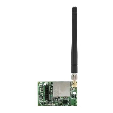
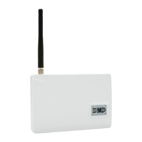
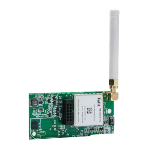
The XR100/XR500 Series panels provide a Diagnostics function to test the Communication integrity and Cellular Signal
strength of the 464-263C. To use Diagnostics, reset the panel, enter the Diagnostics code 2313 (DIAG), and press COMMAND
until COMM STATUS displays.
Communication Status
Select COMM STATUS from the Diagnostics menu. The panel tests the 464-263C for the following items.
• Modem Operating • Cellular Tower Detected • NOC Success
• Identied • Registered • Communication Path Integrity
Cellular Signal
Select CELL SIGNAL from the Diagnostics menu. The panel tests and indicates the strength of the signal
using a bar display. One bar indicates a weak signal and seven bars indicate a strong signal.
Wiring Specications for LX-Bus
When planning an LX-Bus installation, keep in mind the following specications:
1. DMP recommends using 18 or 22-gauge unshielded wire for all keypad and LX-Bus circuits. Do Not use twisted pair or
shielded wire for LX-Bus and keypad bus data circuits. To maintain auxiliary power integrity when using 22-gauge wire do
not exceed 500 feet. When using 18-gauge wire do not exceed 1,000 feet. Install an additional power supply to increase
the wire length or add devices.
2. Maximum distance for any one circuit (length of wire) is 2,500 feet regardless of the wire gauge. This distance can be in
the form of one long wire run or multiple branches with all wiring totaling no more than 2,500 feet. As wire distance from
the panel increases, DC voltage on the wire decreases.
3. Maximum number of devices per 2,500 feet circuit is 40.
Note: Each panel allows a specic number of supervised keypads. Add additional keypads in the unsupervised mode. Refer
to the panel installation guide for specic number of supervised keypads allowed.
4.
Maximum voltage drop between the panel (or auxiliary power supply) and any device is 2.0 VDC. If the voltage at any device
is less than the required level, add an auxiliary power supply at the end of the circuit. When voltage is too low, the devices
cannot operate properly. For additional information refer to the LX-Bus/Keypad Bus Wiring Application Note (LT-2031).
FCC Information
This device complies with Part 15 of the FCC Rules. Afx the included FCC label to the exterior of the panel enclosure in plain sight.
Operation is subject to the following two conditions:
(1) This device may not cause harmful interference, and
(2) this device must accept any interference received, including interference that may cause undesired operation.
Changes or modications made by the user and not expressly approved by the party responsible for compliance could void the user’s
authority to operate the equipment.
NOTE: This equipment has been tested and found to comply with the limits for a Class B digital device, pursuant to part 15 of the
FCC Rules. These limits are designed to provide reasonable protection against harmful interference in a residential installation. This
equipment generates, uses and can radiate radio frequency energy and, if not installed and used in accordance with the instructions,
may cause harmful interference to radio communications. However, there is no guarantee that interference will not occur in a particular
installation. If this equipment does cause harmful interference to radio or television reception, which can be determined by turning the
equipment off and on, the user is encouraged to try to correct the interference by one or more of the following measures:
- Reorient or relocate the receiving antenna.
- Increase the separation between the equipment and receiver.
- Connect the equipment into an outlet on a circuit different from that to which the receiver is connected.
- Consult the dealer or an experienced radio/TV technician for help.
-XX dBm
SIGNAL: ▐▐▐▐
Specications
Primary Power 12 VDC from panel
Current Draw
Standby: 15mA
Alarm (Nominal):
48mA
Peak (~150mS): 85mA
Accessories
381-2 18” Coax Cable
381-12 12’ Coax Extension
381-25 25’ Coax Extension
383 Antenna
386 Wall Mount Antenna Bracket
Certications
Cellular FCC ID: MIVCNN0301
ANSI/UL 1076 Proprietary Burglar
ANSI/UL 1610 Central Station Burglar

