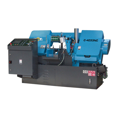
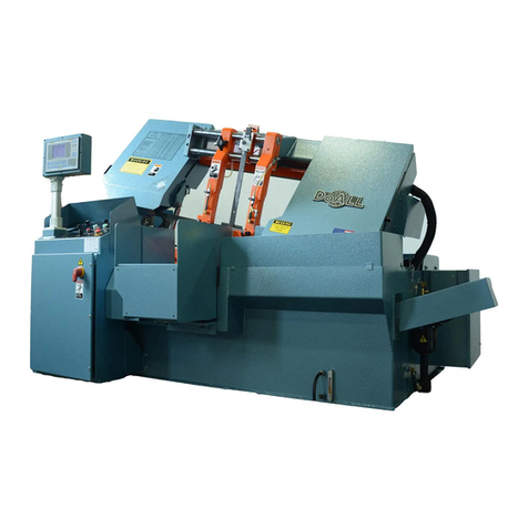
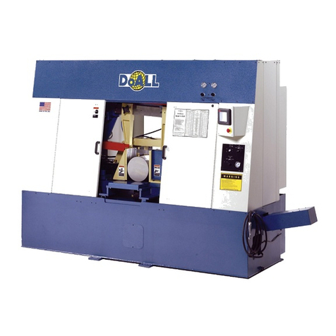
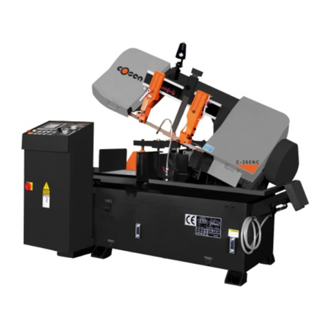
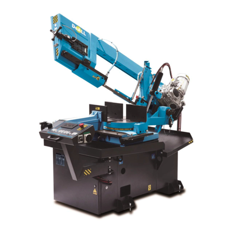
DoAll c-530 nc User manual

Instruction Manual Pag.1
Edition A
INSTRUCTION MANUAL
Band Saw Machine
type
C-530 NC
March 2003

Instruction Manual Pag.2
Edition A
INDEX..................................................................................ERRORE. IL SEGNALIBRO NON È DEFINITO.
CE DECLARATION.........................................................................................................................5
GENERAL WARNINGS ..................................................................................................................6
1. GENERAL INFORMATION.................................................................................................................7
1.1. Goal of this manual...................................................................................................................7
1.2. Regulations to refer...................................................................................................................7
1.3. Manual description....................................................................................................................7
2. MACHINE IDENTIFICATION DATA....................................................................................................8
2.1 Main costructive characteristics.................................................................................................9
2.2. Blade speed...............................................................................................................................9
2.3. Working surface........................................................................................................................9
2.4. Indexing ....................................................................................................................................9
2.5. Vises........................................................................................................................................10
3. HOW TO USE THE INSTRUCTION MANUAL.....................................................................................11
3.1. Who should read the instruction manual ?..............................................................................11
3.2. Where to keep this manual......................................................................................................11
3.3. Strength of this manual...........................................................................................................11
3.4. Manual update.........................................................................................................................11
3.5. How to obtain more copies .....................................................................................................12
3.6. If the machine change owner .................................................................................................12
3.7. Suggestions .............................................................................................................................12
4. LIABILITY LIMITS..........................................................................................................................13
4.1 Inappropriate use of the machine.............................................................................................13
5. TYPE OF USE ALLOWED.................................................................................................................14
5.1. Machine addressee.................................................................................................................14
5.2. Operator ..................................................................................................................................14
5.3. Regulation...............................................................................................................................14
5.4 Typical use...............................................................................................................................14
5.5. Limits using the saw ...............................................................................................................15
5.6. Workable materials.................................................................................................................15
5.7. Work area...............................................................................................................................15
5.8. Work place..............................................................................................................................15
5.9. Command modes, stop, emergency stop and out of service. .................................................16
5.9.1 Command modes ..............................................................................................................16
5.9.1.1. Stop...............................................................................................................................16
5.9.1.2. Emergency stop.............................................................................................................16
5.9.1.3. Out of service................................................................................................................16
5.9.1.4. Safety precautions.........................................................................................................16
6. TECHNICAL DESCRIPTION.............................................................................................................17
6.1. Machine structure....................................................................................................................17
6.1.1. Base frame........................................................................................................................17
6.1.2. Chip conveyor.................................................................................................................17
6.1.3. Indexing ...........................................................................................................................17
6.1.4. Vises.................................................................................................................................18
6.2. Cutting bridge .........................................................................................................................18
6.2.1 Cutting bridge frame.........................................................................................................18
6.2.2 Guiding columns...............................................................................................................18

Instruction Manual Pag.3
Edition A
6.2.3 Columns connection..........................................................................................................18
6.2.4 Lifting cylinder..................................................................................................................19
6.2.5 Blade tension assembly.....................................................................................................19
6.2.6 Band drive assembly.........................................................................................................19
6.2.7 Band brush assembly.........................................................................................................19
6.2.8 Left and right band guides.................................................................................................19
6.2.9 Cutting servo-control ........................................................................................................19
6.2.10 Wheels............................................................................................................................20
6.2.11 Band drive motor (Exhibit A07).....................................................................................20
6.3. Hydraulic power unit...............................................................................................................20
6.3.1 Motor-pump assembly ......................................................................................................20
6.3.2 Oil reservoir ......................................................................................................................20
6.3.3 Solenoid valves.................................................................................................................20
6.4. Electrical system ....................................................................................................................21
6.4.1 Control console.................................................................................................................21
6.4.2 Control enclosure..............................................................................................................21
7. MACHINE PROTECTIONS ...............................................................................................................22
8. HOW TO MOVE THE MACHINE.......................................................................................................23
9. HOW TO INSTALL THE MACHINE...................................................................................................24
10. WHAT TO DO TO PREPARE THE MACHINE TO OPERATE .............................................................25
11. SAFETY DEVICES..........................................................................................................................26
11.1 Limit switches and segnalation devices.................................................................................26
11.1.1. Limit switches................................................................................................................26
11.1.2. speed reducer..................................................................................................................26
11.1.3. Mechanical extra stroke .................................................................................................26
11.1.4. Signals............................................................................................................................26
11.1.5. Led, indicators and signals to avoid danger situations...................................................26
11.1.6. Protection devices..........................................................................................................26
11.2. Fix protections ......................................................................................................................26
11.3. Moveable protections............................................................................................................27
11.4. Safety features set-up............................................................................................................27
12. USE OF THE MACHINE..................................................................................................................28
12.1. How to use the machine – The Saw 3 control.......................................................................28
12.1.1 What the Saw 3 is ...........................................................................................................28
12.1.2 Switching the Saw 3 ON.................................................................................................28
12.1.3 Machine status icons.......................................................................................................29
12.1.4 Status icons .....................................................................................................................29
12.1.5 Manual cycle .......................................................................................................29
12.1.5.1 Manual operation with the material handling (option) ...............................31
12.1.6 Semi automatic cycle ...........................................................................................31
12.1.7 Automatic cycle ....................................................................................................31
12.1.7.1 Programs directory ..........................................................................................31
12.1.7.2 Create a new cutting program ......................................................................32
12.1.7.2.1 How proceed to create your working list (only for material handling).................32

Instruction Manual Pag.4
Edition A
12.1.7.3 Running a program.......................................................................................................33
12.1.7.4 How to modify the current cutting program (PGM function)......................................33
12.1.8. How to select the type of coolant (for machine which applies mist lubricator units)....33
12.1.9 General information concerning parameters setup .................................................33
12.1.10 Select your country language .............................................................................36
12.1.11 Inputs & outputs testing screen ..........................................................................36
12.1.12 Software update.............................................................................................................36
12.1.13 Help function.................................................................................................................37
12.2. Head feed control..................................................................................................................37
12.2.1 How to select the feed system (option)...........................................................................37
12.3. Automatic workstop (option)................................................................................................37
12.3.1 How to reset the automatic workstop sensor ..................................................................38
12.4. Band deviation monitor (option)...........................................................................................38
13. HOW TO DISMANTLE THE MACHINE............................................................................................39
14. ORDINARY PROBLEMS..................................................................................................................40
14.1. Base.......................................................................................................................................40
14.1.1. Base (Exhibit A02).........................................................................................................40
14.1.2 Chip conveyor.................................................................................................................40
14.1.3. Index...............................................................................................................................40
14.2. Cutting bridge .......................................................................................................................40
14.2.1 Columns..........................................................................................................................40
14.2.2 Connection bar................................................................................................................41
14.2.3 Lifting cylinder................................................................................................................41
14.2.4 Blade tension assembly...................................................................................................41
14.2.5 Band drive assembly.......................................................................................................41
14.2.6 Guide arms......................................................................................................................41
14.2.7 Band brush assembly.......................................................................................................41
14.2.8 Wheels.............................................................................................................................41
14.2.9 Servo-cutting device .......................................................................................................42
14.2.10 Rapid approach .............................................................................................................42
14.3 Coolant system.......................................................................................................................42
14.4 Hydraulic power unit..............................................................................................................42
14.5 Electric control panel .............................................................................................................42
15. MAINTENANCE .............................................................................................................................43
15.1 Lubrication.............................................................................................................................43
15.2. Problems ...............................................................................................................................44
15.3. Blade replacement.................................................................................................................44
16. REMAINING DANGERS ..................................................................................................................46
17. PERSONEL TRAINING...................................................................................................................47
18. MACHINE DISMANTLE .................................................................................................................48
PROOF OF TEST............................................................................................................................49
SPARE PARTS LIST ......................................................................................................................50
ELECTRICAL AND HYDRAULIC SCHEMATICS..................................................................72

Instruction Manual Pag.5
Edition A
CE DECLARATION
We declare that the product “Band saw machine type C-530NC”:
Serial number 23151 Year of production 2003
referred to in this declaration is in compliance with :
• CEI EN 60204-1
• UNI EN 292/1
• UNI EN 292/2
and :
1. EEC Machine Directive 89/332 dated June 14, 1989 and amendments ;
2. EEC Low Voltage Directive 73/23 and amendments ;
3. EEC Directive 89/336 and amendments.
This product uses only tested and certified components, which meet the CE requirements, unless
otherwise specified.
Vanzago, March 2003 SEGATRICI S.R.L.
Via Ferrario 13
20010 Vanzago – MI
Alessandro Rescaldani
(Amministratore)

Instruction Manual Pag.6
Edition A
GENERALWARNINGS
This machine was design and built using the state of the art techniques, and with respect of the machine tools European
Laws.
Notwithstanding what above, it is implicit that working underestimating or forgiving the dangers which this kind of ma-
chinecangenerate,theoperatorcouldcauseaseriousinjurytohim/herself.
Therefore,the operatorshould carefullyreadthe entireinstruction manual,andrespect strictlywhatinitprescribed.
Inparticular, pleasepayattentionto thefollowingsuggestions:
1. Keepalwaysyourworkingareaclean.
2. Avoid to keep in your working area pieces of material, chips, cans, or other things which could reduce the possi-
bilityofmovementfortheoperatororevengeneraterisksofinjury.
3. Be always cautious using the machine, because, even if it is protected in every dangerous spot, it can be a dan-
gerous equipment,andthusithastobeusebeingparticularlycareful andaware.
4. Give immediately notice to your supervisor if the machine needs to be maintained or serviced, even if the prob-
lemiscausedby inexperience.Anincorrectuseofthemachinecanbedangerousandcancauseinjuries.
5. Donottrytorepairtheproblemifyouarenotsureofwhatcausedit.
6. Never serviceormaintainthemachinewhenitisrunning.Alwaysturnitoff.
7. Neverleavethemachineworkingwithoutrespectingthesafetyrulesorremovingthesafetydevices.
8. Removeelectricalpowerwhenthemachineisnotworking.
9. Alwayswearprotectivecloths,especiallywhenreplacingtheblade.
10.Neverdoanythingimprudent.
11.Nevertouchtheunprotectedpartoftheblade.
12.Nevercutanypieceshorterthantheshortestpossiblelength.
13.Neverstartcuttingifthematerialisnot firmlyclampedbythevises.
14.Movethematerialonlyifthecuttingbridgeiscompletelyup.

Instruction Manual Pag.7
Edition A
1.GENERAL INFORMATION
1.1.GOALOFTHISMANUAL.
This manual wants to explain instructions about how to operate safely, usingtexts, drawings, pictures and diagrams used by
themselvesorcombinedto instructtheoperatortousethemachine.
1.2.REGULATIONSTOREFER.
This manual was written to complyto the European Machine Directive UNI-EN 89/392 and following modifications, and
basedon UNI-EN292/1e292/2 concerningasafeuse ofthemachine.
1.3.MANUALDESCRIPTION
Thisdocument containsinformation needed to:
• installandmakethemachinework
• normaluseofthe saw
• howtomaintainthemachine
• howto servicethemachine
• howtodismantlethemachine

Instruction Manual Pag.8
Edition A
2.MACHINEIDENTIFICATION DATA
TAB 2.1 Identificationdata
Description Denominationorvalue Plate
N
am
e
BandSawmachine
Type C-530NC Yes
Serialnumber 23151 Yes
Year 2003 Yes
Voltageandfrequency 400V 3ph+N+GND±10% 50 Hz ±1% Yes
Hydraulicpowerunit Yes
Controlcircuit 24Vdc 50Hz
Dangerousarea Areaaround themachine (1.5meters)
Workingplace Machinecontrolpanel
Typeoftool Bandsawblade
Machine
Description Bandsawmachine, typeC-530NC
Totalamperage A 28
Maximumpower kW 12.5
Approximateweight Kg 4.000
TAB 2.2 TechnicalCharacteristics
Description C-530NC
Roundcuttingcapacity mm 530
Squarecuttingcapacity mm 530x530
Indexstroke mm 500
Banddrivemotor kW 7.5
Bladedimension mm 6400x54x1.6
Bladespeed m/1’ 20-100
Hydraulicpumpmotor kW 4
Coolantpump motor kW 0.25
Hydraulicpumpcapacity l/1’ 27
Voltageofmotors V 400c.a.
Controlcircuit voltage V 24 dc
Cuttingkerf mm 1.8
Hydraulicreservoir l 50
Coolantreservoir l 70
Workingheight mm 770
Machineoveralldimension mm 2800x2500x2800H
Shippingdimension mm same
Color RAL DoALLRoyalblue
Movingcomponentscolor RAL Beige1001
Maximumnoiselevel dB 80
Weight(Approximate) Kg 4.000

Instruction Manual Pag.9
Edition A
2.1MAINCOSTRUCTIVECHARACTERISTICS.
Themachineuses :
• Cuttingprogrammer SAWIII
• Troubleshuttingcontrol panel “CheckPanel”
• Automaticfeedingcontroldevice
• Bladespeedcontrolled byanACmotorand avariablefrequencydrive.
• Workingsurfacewithnon-wearable materials.
• Ballprecisionscrewstocontrol index movements.
• Viseswithtemperedinserts.
• Pressurereducervalveson vises.
• Self-positioningbandguides.
• Carbideinsertsmountedinside theband guides.
• Bandbrushpowered byhydraulicmotor.
• Chipconveyorpowered byhydraulicmotor.
• Cuttingbridgemountedon chromatecolumns.
• Weldedframe.
• CastingsingrayironC26
• Hydraulicbandtension.
The saw is built to work in automatic also without an operator. A special design in the rearvise and workingsurface area al-
lowsthemachinetocutslightlyirregularbars.
2.2.BLADESPEED
Theblade speed is controlledbyan AC motor and avariablefrequencydrive, whichallowtoregulatethebladespeedwithin
arangeof 0- 100 m/1’. Inthiswaythemachine cancutboth hardsteelsand aluminum.Adigitalreader constantlyshowsthe
bladespeed .
Theblade speedcanbe adjusted :
• inautomaticcycleduringtheediting;
• inmanual usingarotarypotentiometer mountedonthe controlpanel.
2.3.WORKINGSURFACE
The material that has to be cut layson a roller waythat covers the entire stroke of the machine. The distance between the roll-
ersis studied to avoidthatshortpiecescan fall.
2.4.INDEXING
The material is fed byan index with hydraulic vises, which clamp the piece and move it under the blade. The index moves
on round chrome guides located underneath the roller table, and it is controlledbya tempered steelprecision ball screw. The
index has two speeds : fast to move and slow to precisely position the piece. A rotary encoder (with a precisionof a tenth of
amillimeter)controlstheposition oftheindex.

Instruction Manual Pag.10
Edition A
2.5.VISES
Thesawvises are hydraulic.Theclampingpart of themhavea tempered insert bolted. Besides,the hydrauliccircuit thatcon-
trolsthe viseshas a pressurereducer valvewitha gaugetoavoid toclampwith toomuch strengththe materialanddeform it.

Instruction Manual Pag.11
Edition A
3.HOW TOUSETHE INSTRUCTION MANUAL
3.1.WHOSHOULDREADTHEINSTRUCTIONMANUAL ?
TAB3.1Whoshouldread themanual
Description Operator Internalservice
Mechanical Electrical
InstructionManual Yes Yes No
Electrical Schematic No No Yes
Theelectrical schematicis included inthis manualandcannot besuppliedseparately.
3.2.WHERETOKEEPTHISMANUAL
This manual, that is provided along the machine in one copy, should be kept wherethe machine islocated, in a safeand pro-
tectedplace,tobe consultedifnecessary.
3.3.STRENGTHOFTHISMANUAL
1. This manual reflects the state of the art at the time the machine was built,and cannot beconsidered replaceable bya
newerversion.
2. Thismanualhas fullforceforall thelifeof themachineit goesalong.
3. The customer is not allowed to copytotally or partiallythis manual to reach goals different than the oneof the origi-
nalmanual,and to avoidthatapartialdocumentationreplacestheoriginal one.
3.4.MANUALUPDATE
The manufacturer does not have to update this manual if improvements are adopted onnewer machines ofthe same kindof
theone thismanual make referenceto.
Thismanual willbe updated bythe manufactureronlyif :
• thismanualcontainsmistakes,errors,orsomethingis missing;
• theoriginal machineis modifiedbythemanufacturer.
Marginal errors or missing elements, if considered important for the correct work of the machine and its safe use will be im-
mediatelynotified throughan“ErrataCorrige”.
To modify this manual the manufacturer will bring all the copyof the same edition back and then new copies will be sent to
thecustomer.
Thelatest versionis marked withhigherletter(A, B....).The firsteditionis called“Edition A”.

Instruction Manual Pag.12
Edition A
3.5.HOWTOOBTAINMORECOPIES
If necessary, the customer can obtain new copies of this manual simply making a written request and mentioning on it the
machineserialnumber.
If copiesare requested,the manufacturerhasthe rightto bepaidto issuethem.
3.6. IFTHEMACHINECHANGEOWNER
If the original customer sales the machine, he/she should notifythe manufacturer that the machine changed ownership,so to
allowthemanufacturertoinformthenewuseronthedangersandlimits ofliability.
3.7.SUGGESTIONS
The customer should notify the manufacturer if improvements are necessaryand where they are to increase an easyunder-
standingofthis manual/

Instruction Manual Pag.13
Edition A
4.LIABILITYLIMITS
Themanufacturer cannotbe responsible ifthe machineifused inonefollowingways,whichare classifiedas inappropriate :
4.1INAPPROPRIATEUSEOFTHEMACHINE
Ithas tobeconsidered inappropriatetheuse ofthe machineif:
• thesafetyrulesarepartiallyarecompletelyunattended;
• whatthemanufacturerprescribed isnot done ;
• the a danger or injuryis due to an incorrect installation or assemblyof the machine, and it was not done bythe customer
orunder hissurveillance ;
• wrong installationofprotectiveequipment aftermaintenance or service;
• hydraulic orelectrical problemsdueto theproducerof thecomponentand notto the producerof themachine;
• bigdeficiencyinmaintenance;
• modificationsormaintenanceon themachine without authorizationofthe manufacturer;
• useofatypical tools, otherthan theonessuggestedbythemanufacturer;
• useofnon-originalspareparts, otherthanthe onesuggestedbythemanufacturer;
• Partialorcompletenon-observance ofthe instructions ;
• machineusedbyuninstructed operatorswithout controlofan expert operator;
• movementormachiningofnon-typicalmaterials,or oversize andoverweightmaterialscomparedto theones indicated;
• natural calamities, including earthquakes, floods or others which could provoke danger or faults to the machine or its
structureseasytobeidentified;
• ifelectrical,pneumatic ormechanical safetyfeatureswere partiallyorcompletelyremoved;
• maintenancewhilethemachineisworking;
• whenpartsofthe machineare tensioned usingtemporaryconnections,withoutprotectionor usingfaultymaterials;
• apersonwithoutexperienceis withinthedangerarea while themachine isrunning;
• apersonwithexperienceis withinthedangerarea while themachine isrunningwiththeautomatic cycle.
It has to be considered inappropriate also when the machine runs without enough surveillance to assure the operator
safetyor toassure thatthemachine canrunproperly.

Instruction Manual Pag.14
Edition A
5.TYPEOF USEALLOWED
5.1. MACHINEADDRESSEE
Thismachinewas designandbuilttocomplyaprofessional use,meaningthat,besides thetechnicalknowledgerequired,it is
necessaryto havea specificknowledgetooperatethe sawtoobtain therequired goals.
5.2.OPERATOR
Thesawoperatorshould haveexperience onsimilar typeofmachine.Peoplewith lowornone experience mustbeeducated,
followedand watchedbyasupervisor with enoughexperience and ability.
Therefore, the operator must be aware about dangers related to the use of this machine, and dangers due to normal handling
ofmetallicmaterials, similar,orheavy.
Thismachine cannotbe used bypeople withhandicapsor disables.
5.3.REGULATION
Designingandbuildingthismachinewerespectedthefollowinglawsandrules:
• UNIrules
• CEIrules
andmore indetail, concerningthe safetyfeatures(typeAandBrules):
• European CommunityMachine directive89/392;
• CEI-EN 60204-1andrelated rulesconcerningelectric’s,with respectofEC directive73/23;
• EN292/1
• EN292/2
If not clearly specified, every component used on this machine was UNI and CEI approved at the time it was bought or
made.
5.4TYPICALUSE
This machine was designed and built to cut metallicmaterials fed byautomatic systems and with overallsize non largerthan
theones listedin the chart below(5.4). The sawcanmove :
1. movementofthematerialbefore andaftereach cut ;
2. verticalmovementofthecuttingbridge;
3. bladerotation.
Allthese movementscould take placeat thesametime.
Thesaw hasthefollowingperformance :

Instruction Manual Pag.15
Edition A
Tab.5.4 Characteristic MIN MAX
Cuttingspeed cmq/m 5 140
Materialfeedingspeed Mt./m 30 300
Cuttingbridgefallingrate(w/omaterial) Mt./m 3 30
Barssize mm ∅10(manual) ∅520
Barweight kg. 1.336 3.528
5.5.LIMITSUSINGTHESAW
Themachinehastwo limits ofusedueto:
• operator’sinexperience
• materialsizeandweight
1. Theoperator’s experience isparticularlynecessarywhenthe sawrunsin manualcycle;
2. materialsizeandweightmustbe within theones aboveshown.
5.6.WORKABLEMATERIALS
This machine can cut only metallic bars, pipes and tubing. Every other use will is considered inappropriate use of the ma-
chine.
5.7.WORK AREA
This machine has to work in industrial environment. It is design to make mechanical machining under human control, but
theoperator presenceis not requiredcontinuously.
Itisrecommendedtokeep clean andfree of interference the areacloseto themachine.
Thismachine usea mixtureof oil andwateras coolantliquid. Thus,theworkingareacould beslipperyanddirty.
THIS AREA MUST BE MARKED BY AN APPROPRIATE SIGNAL.
5.8.WORKPLACE
Themachinehas oneworkplace in frontofthecontrol panel.
Asecond temporarywork placeisaside thevises,the registerthem, andtochangethe blade.
Each work place must be easy to reach when necessary, without interference, even temporary. The machine can work
automaticallywithout operator, who must be present duringthe manual operations ofloading andunloading, and controlthe
controlpanel operations.

Instruction Manual Pag.16
Edition A
No specific illumination is required, but the work place must be well illuminated to respect the requirements set bypresent
safetyrules.
Onlyauthorized people andmaintenance personnelshouldbe allowedtoreach thesawwork place.
Theoperator mustbe equipped withpersonal protectioninstruments,like glovesand safetyglasses.
5.9. COMMANDMODES,STOP,EMERGENCYSTOPANDOUTOFSERVICE.
5.9.1Commandmodes
Thesaw canbe controlled intwo differentways:
1. Automaticmode, allautomaticcommandsareenable.
2. Manualmode, all thecommands are switchedto thecontrolpanel push-buttonandswitches.
5.9.1.1.Stop
Thesawstops whenthecuttingcycleisover.
5.9.1.2.Emergencystop
Theemergencystop stops themachineremovingtension fromthecontrol circuit.
5.9.1.3.Outofservice
The saw can be turned out of service removing tension from the control circuit, switching off the main disconnect switch lo-
cated on the front face of the enclosure. A signal saying “Out of service” must be placed on the machine, and it is operator’s
dutyto verifythat themachinecannot generatedangersituations.
5.9.1.4.Safetyprecautions
Themachine cannotgeneratedangersituationwhen itiscompletelywithoutelectric orhydraulicpower.
Concerning the electrical power, the machine mustbe completelydisconnected from electrical sources,turning of theelectri-
cal socket on the building electrical panel. The machine cannot be considered completely safe if the only main disconnect
switchofthe machineisturnedoff.

Instruction Manual Pag.17
Edition A
6.TECHNICALDESCRIPTION
6.1.MACHINESTRUCTURE
Thissaw ismanlymadeby:
1. Baseframe
2. Cuttingbridge
3. Hydraulic powerunit
4. ControlPanel
5. Coolantsystem
Pos. Tab6.1.Baseframe
6.1.1. Baseframe
6.1.2. Chipconveyor
6.1.3. Indexing (Onlyforautomatic machines)
6.1.4. Vises(Onlyforautomatic machines)
6.1.1.Baseframe
The machine frame is welded and machined. The material used is Fe 37. In the weldment there are two reservoirs, one for
thecoolant liquid,and the secondfor thehydraulicoil.
The frame is machined to avoid corners or abrasive points that could be dangerous. It is painted with two layers of paint, the
firstof whichprevent corrosion.
Itis machinedtobe assembledwith other machinecomponents.
6.1.2. Chipconveyor
Itis standardonautomaticmachinesand optionalon semi-automaticmachines,anditis madeby:
• Bendedandwelded framewithFe37steel.
• Hydraulicallypoweredchip screw.
• Protective brackets.
• Chiptank
• Coolantreservoir
Thechip conveyorremoves chipscoming from thebandbrush andfromthe cut,takingthemoutside themachine.
6.1.3.Indexing
Usedonlyforautomaticmachines,itincludes:
• Indexframewelded andmachined, andmadeusingFe37steel.
• Precisionball bearingscrew,tomove backwardandforward theindexframe.
• Steelvises toclamp the material,controlled byhydraulic cylinders.

Instruction Manual Pag.18
Edition A
Two limit switches are mounted on the index, the first to set the zero, and the second to control when the index is out of ma-
terial.
6.1.4.Vises
Itincludes :
• clampingvisesmade withagrayiron castingG26, machined. Visesarecontrolled byhydrauliccylinders.
6.2.CUTTINGBRIDGE
Pos. Tab6.2Cuttingbridge
6.2.1 Cuttingbridgeframe
6.2.2 Guidingcolumns
6.2.3 Columnsconnection
6.2.4 Liftingcylinder
6.2.5 Bladetensionassembly
6.2.6 Bladedriveassembly
6.2.7 Bandbrushassembly
6.2.8 Leftand rightbandguide
6.2.9 Cuttingservo-control
6.2.10 Wheels
6.2.11 Blanddrivemotor
6.2.1Cuttingbridgeframe
Thecuttingbridgeframe is asteel Fe37weldment ;itis machinedto be assembledwith othermachinecomponents.
Thebridgewas designand builtto endurethecuttingstrength,keepingenoughsturdiness.
Theframeismechanicallymachinedandpaintedwith anti-corrosionagentsandwithnitro paint.
The blade is completely protected where it does not work. Covering the wheels, there are two doors that can be opened to
changetheblade. Twosafetyswitches aremounted onthesedoors, sotostop themachineif thecovers are notin position.
Theblade rotateson the wheels,one ofwhichis driven,andthe otheroneis idler.
6.2.2Guidingcolumns
Thecolumnsguideverticallythecuttingbridgemovement.Theyaremadewith chromebars,hardenedandgrinded.
6.2.3Columnsconnection
Made using a Fe52 steel square tube, the columns connection connects and makes the guiding columns sturdy. It is fastened
tothe columnsthroughtwolocknuts. Theliftingcylinderis fastenedto thecenterof theconnectiontube.

Instruction Manual Pag.19
Edition A
6.2.4Liftingcylinder
Thisisan hydrauliccylinder,withchrome rodandlapped cylinder.Theliftingcylinderisadoubleeffect cylinder.The headis
fastenedto thecolumns connection, andthe finalendof therodis fastenedtothe cuttingbridgeusinga locknut.
6.2.5Bladetensionassembly
Thisassembly hastokeep the blade at the right tension when the machine is running. There isasteel slidewhichsupport the
idler wheel shaft. An hydraulic cylinder, that works on the slide, keeps the band in tension. A limit switch protects the ma-
chineturningimmediatelyoffthemachineifthebladebrakes.
6.2.6Banddriveassembly
Theband is powered byanAC motorwhich automaticallyregulatesthe rotation speed.Usingtwo pulleysandthreeV-belts,
the motor makes the speed reducer turning. On the other end of the reducer there is the drive wheel, that is fastened to the re-
ducerusingacolletlocking.
6.2.7Bandbrushassembly
Aband brushis powered byan hydraulicmotor,anditcleans theteethremovingthe chips.
6.2.8Leftandrightbandguides.
Theband guideshaveto:
• straightenthe blade comingoutthewheel, andkeepitverticalhelpingtheblade insertionbetween the inserts.
• protectthepartofthebladethat isnot cutting.
Leftguidearm:Moveshorizontallyon guidesmachinedonthe bridge,anditis movedbythemovementof thevise.
Rightguidearm: Fixed onthe cuttingbridge.Itsupportsthecuttingservocontrol.
Boththeguidearmshavecarbide inserts.
6.2.9Cuttingservo-control
The Cutting servo-control automaticallycontrols the saw feed rate. A servovalve has an extension which touches the blade
back,and registersthe effortstocut thepiece. Theservovalvemodifies thefeedrate for:
• shapeof piece
• materialhardness
• bladewear condition
Theoperator, readingontheknob, isallowedto changethepreferredfeed rate.

Instruction Manual Pag.20
Edition A
6.2.10 Wheels
Madeusingcast iron G26,andlathe machined.Theyare fastenedasfollow :
• theidlerwheelis fastenedonthe bandtensionassembly,andit turnson ballbearings;
• theband drivewheelisfastenedusingacollectlockingonthe reducershaft.
Thewheelsdiameteris largerthenthemaximum materialheightthatcanbecutbythesaw..
6.2.11Banddrivemotor(ExhibitA07)
The machine mounts a self-cooling AC electric motor. On the shaft there is a three throats pulley, on which there are 3 V-
beltsto connectmotor and reducer
6.3.HYDRAULICPOWERUNIT
The power unit has a double location inside the machine frame. Underneath the infeed roller table there is the oil reservoir,
andunder theoutfeed roller tablethere areallthe solenoidvalves.The powerunitis madeby:
Pos. Tab6.3. Hydraulicpowerunit
6.3.1 Motor-pumpassembly
6.3.2 Oilreservoir
6.3.3 Solenoidvalves
6.3.1Motor-pumpassembly
Electrical motor andpumpareconnected byanelasticcoupling.
6.3.2Oilreservoir
It is in the machineframe, and it has a maximum and a minimum level indicators, and asuction filter. Onthe left sideof the
infeedrollertablethereisaplugwhichallowstorefillthereservoir.Thehydraulicsystemhas2 filters:
• a 250micron 45litres suction filter
• a 60micron45 litersoutflow filter
These two filters have to be removed when changing the oil for the first time (after 500 working hours), washed using tri-
chloroethylene anddriedblowingair.
6.3.3Solenoidvalves
Thesolenoid valvesare mounted onblocks, andthecontrol thehydraulic movements.
Other manuals for c-530 nc
1
Table of contents
Other DoAll Saw manuals

DoAll
DoAll ZV-3620 User manual

DoAll
DoAll 500SNC User manual

DoAll
DoAll 800SNC User manual

DoAll
DoAll C-3350NC User manual

DoAll
DoAll C-8056SA User manual

DoAll
DoAll C-520NC User manual

DoAll
DoAll DS-320SA User manual

DoAll
DoAll c-530 nc Parts list manual

DoAll
DoAll 3613-V5 User manual

DoAll
DoAll C-260 NC Parts list manual
Popular Saw manuals by other brands

VITO
VITO PRO-POWER VISCC12210 instruction manual

TOOLCRAFT
TOOLCRAFT TO-7453617 Original instructions

Milwaukee
Milwaukee HEAVY-DUTY CIRCULAR SAW Operator's manual

Makita
Makita XSC01 instruction manual

Gude
Gude GRK 250/500 Translation of the original instructions

Evolution
Evolution RAGE 1-B Original instructions