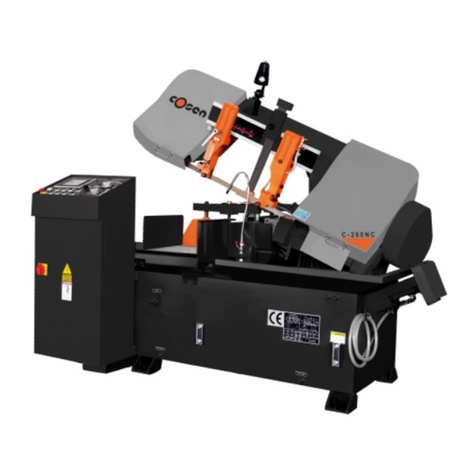
DoAll C-260 NC Parts list manual

INSTRUCTION & PARTS MANUAL Pag.1
Edition A
INSTRUCTION &
PARTS MANUAL
for
Band Saw Machine type
C-260 NC
YEAR OF PRODUCTION
2001
SERIAL NUMBER
21115

Instruction & Parts Manual Pag.2
Edition A
Dear Customer,
First of all, thank you for choosing a DoAll product.
DoAll represents an important reference in the metal cutting business worldwide,
and its production has always been recognized as synonymous of quality.
All machine componets have been designed and manufactured to guarantee best
possible performances. To keep this high standard, we kindly invite you to use only
original DoAll spare parts.
DoAll band saw machines are CE marked and in the following pages the reader will
find a CE declaration which follows the European Directive 89/392 requirements.
DoAll is sure to assure with this machine the state of the art solutions for the opera-
tor safety, and to be part of the general improvement of labour conditions.
DoAll

Instruction & Parts Manual Pag.3
Edition A
We declare that the product “Band saw machine type C-260 NC”:
Serial number 21115 Year of production 2001
referred to in this declaration is in compliance with :
•CEI EN 60204-1
•UNI EN 292/1
•UNI EN 292/2
and :
1. EEC Machine Directive 89/332 dated June 14, 1989 and amendments ;
2. EEC Low Voltage Directive 73/23 and amendments ;
3. EEC Directive 89/336 and amendments.
This product uses only tested and certified components, which meet the CE requirements, unless
otherwise specified.
Vanzago, December 2001 SEGATRICI S.R.L.
Via Ferrario 13
20010 Vanzago – MI
Alessandro Rescaldani
(Amministratore)

Instruction & Parts Manual Pag.4
Edition A
INDEX
Generalinformation
1.Generalinformation.
2.Machineidentificationdata.
3.Howtousethisinstructionmanual.
4.Manufacturerliabilitylimits.
5.Typeofuseallowed.
6.Technicaldescription.
7.Machineprotections.
8.Howtomovethemachine.
9.Howtoinstallthemachine.
10.Whattodotopreparethemachinetooperate.
11.Safetydevices.
12.Machineuse,calibrationetune-up.
13Howtodismantlethemachine.
14.Howtoservicethemachine(ordinaryproblems).
15.Maintenance
16.Remainingdangers
17.Personneltraining
18.Machinedismantle
Exhibit
Proofoftest A
Electricalschematic B
Hydraulicschematic C
Spareparts D

Instruction & Parts Manual Pag.5
Edition A
GENERALINFORMATION
This machine hasbeen designed and built adopting the state of the art technologies, and with respect of the European Laws
formachine tools.
Notwithstanding what above, itis implicit that workingunderestimating or forgetting the dangers related to this kind of ma-
chinecangenerate,theoperatorcouldcauseseriousinjuriestohim/herself.
Therefore,theoperatorshould carefullyreadtheentireinstructionmanual,and respect strictlywhatprescribedinit.
Inparticular,pleasepayattention tothefollowingsuggestions:
1. Keepalwaysyourworkingareaclean.
2. Avoid tokeep in your working area pieces of material, chips, cans, or other things which could reduce the possi-
bilityofmovementtotheoperatororevengeneraterisksofinjury.
3. Be always cautious using the machine, because, even if it is protected in every dangerous spot, it can be a dan-
gerous equipment,andthusithastobeusebeingparticularlycareful andaware.
4. Give immediately notice to your supervisor if the machine needs to be maintained or serviced, even if the prob-
lemiscaused byinexperience.An incorrectuseofthemachinecanbedangerousandcancauseinjuries.
5. Donottrytorepairtheproblemif youarenotsureofwhatcausedit.
6. Never serviceormaintainthemachinewhenitisrunning.Alwaysturnitoff.
7. Neverleavethemachineworkingwithoutrespectingthesafetyrulesorremovingthesafetydevices.
8. Removeelectricalpowerwhenthemachineisnotworking.
9. Alwayswearprotectivecloths,especiallywhen replacingtheblade.
10.Neverdoanythingimprudent.
11.Nevertouchtheunprotectedpartoftheblade.
12.Nevercutanypieceshorterthantheshortestpossiblelength.
13.Neverstartcuttingifthematerialisnot firmlyclampedbythevises.
14.Movethematerialonlyifthecuttingbridgeiscompletelyup.
Instruction & Parts Manual Pag.6
Edition A
1.GENERALINFORMATION
1.1.GOALOFTHISMANUAL.
This manual wants to explain instructions about how to operate safely, usingtexts, drawings, pictures and diagrams used by
themselvesor combinedto instructtheoperatortousethemachine.
1.2.REGULATIONSTOREFER.
This manual was written to complyto the European Machine Directive UNI-EN 89/392 and following modifications, and
basedon UNI-EN292/1 e 292/2concerningasafeuseofthe machine.
1.3.MANUALDESCRIPTION
Thisdocumentcontainsinformation needed to:
•installandmakethemachinework
•normaluseofthe saw
•howtomaintainthemachine
•howtoservice themachine
•howtodismantlethemachine

Instruction & Parts Manual Pag.7
Edition A
2.MACHINEIDENTIFICATIONDATA
TAB2.1 Identificationdata
Description Denominationorvalue Plate
Name BandSawmachine
Type C-260NC Yes
Serialnumber 21115 Yes
Year 2001 Yes
Voltageand frequency 400V3f+N ±10% 50Hz ±1% Yes
Hydraulicpowerunit Yes
Controlcircuit 24Vdc
Dangerousarea Areaaroundthemachine(1.5meters)
Workingplace Machinecontrolpanel
Typeoftool Bandsawblade Machine
Description Bandsawmachine,typeC-260NC
Totalamperage A 19.5
Maximumpower kW 6.3
Approximateweight Kg 2.000
TAB2.2 Technical Characteristics
Description C-260NC
Roundcuttingcapacity mm 260
Squarecuttingcapacity mm 260x 260
Index stroke mm 500
Banddrivemotor kW 4
Bladedimension mm 4.900x34x1.1
Bladespeed m/1’ 20-100
Hydraulicpumpmotor kW 1.5
Coolantpumpmotor kW 0.3
Hydraulicpump capacity l/1’ 14
Voltageofmotors Vac 400
Controlcircuitvoltage Vdc 24
Cuttingkerf mm 1.6
Hydraulicreservoir l 55
Coolantreservoir l 65
Workingheight mm 850
Machineoveralldimension mm 2300x1900x1850
Shippingdimension mm 2300x1700x1850
Color DoALLRoyalblue
Movingcomponentscolor RAL Beige1001
Maximumnoise level dB 80
Weight(Approximate) Kg 2.000

Instruction & Parts Manual Pag.8
Edition A
2.1MAINCOSTRUCTIVECHARACTERISTICS.
Themachine uses :
☺NC controller with operator display and 28 customizable function keys integrated.
☺Multi language diagnostic with info messages.
☺Material libraries.
☺Band speed readout integrated.
☺Constant feed pressure control.
☺Band wheel drive with AC inverter and planetary reducer.
☺Automatic guide arm.
☺Carbide faced saw guides with large diameter lead in rollers on both guide arms.
☺Automatic chip conveyor.
☺Hardened, ground, anti-wear steel plates on all work clamping surfaces.
☺Ground, hardened and hard-chrome plated guide columns.
☺Power driven band cleaning brush.
☺Hydraulic band tension.
☺Recirculating, coolant system, pump 400/50/3, applied through nozzle.
☺Chip container.
☺Rapid saw head approach control.
☺Out of stock sensor.
☺Band wheel door interlocks.
☺Blade guards.
☺Automatic band kerf compensator.
☺C26grayironcastings
The saw is built to work in automatic also without an operator. A special vise design allows the machine to cut slightly ir-
regularbars.
2.2.BLADESPEED
Thebladespeedis controlled byan AC motor and avariablefrequencydrive,whichallow toregulatethebladespeed within
arangeof 0-100m/1’.Inthiswaythemachinecancut both hardsteelsandaluminum. Adigital reader constantlyshowsthe
bladespeed.
Thebladespeed can beadjusted:
•inautomaticcyclewhileediting theprogram;
•anytime, by pressing the keyson thecontrol panel.
2.3.WORKINGSURFACE
The material that has to becut lays ona roller waythat covers the entire strokeof the machine. The distance between the roll-
ersisstudied toavoid thatshortpiecescan fall.
2.4.INDEXING

Instruction & Parts Manual Pag.9
Edition A
The material is fed byan index with hydraulic vises, which clamp the piece and move it under the blade. The index moves
on round chrome guides located underneath the roller table, and it is controlled byan hydraulic cylinder. The index has two
speeds: fast to quicklyapproach to the set lenght and slow to precisely position the piece. Anencoder (with a precision of a
tenthofamillimeter)controlsthepositioningoftheindex.
2.5.VISES
Visesarehydraulic.Thejawsaretempered.
TAB2.3 Cutting tolerances Machine
Description C-260NC
Onthelength mm ±0,15mm/500mm
Ontheperpendicularity mm ±0,2mm/100mm
3.HOWTO USETHEINSTRUCTIONMANUAL
3.1.WHOSHOULDREADTHEINSTRUCTIONMANUAL ?
TAB3.1Whoshould read themanual
Description Operator Internalservice
Mechanical Electrical
InstructionManual Yes Yes No
Electrical Schematic No No Yes
Theelectricalschematicis included inthismanualandcannot be suppliedseparately.
3.2.WHERETOKEEPTHISMANUAL
This manual, thatis providedalong themachine in one copy, should be kept where the machine is located, in a safe and pro-
tectedplace, tobeconsultedif necessary.
3.3.STRENGTHOFTHISMANUAL
1. This manual reflectsthe stateof theart at the time the machine was built, and cannot be considered replaceable bya
newerversion.
2. Thismanualhasfullforceforallthelifeofthemachineit goesalong.
3. The customer is not allowed to copytotally or partiallythis manual to reach goals different than the one of the origi-
nalmanual, and toavoid thatapartial documentationreplacesthe originalone.
3.4.MANUALUPDATE

Instruction & Parts Manual Pag.10
Edition A
The manufacturer doesnot haveto updatethis manual if improvements are adopted on newer machines of the same kind of
theonethismanualmakereferenceto.
Thismanualwillbe updated bythemanufactureronlyif:
•thismanualcontainsmistakes,errors,orsomethingis missing;
•theoriginal machineis modified bythemanufacturer.
Marginal errorsor missingelements, if considered important for the correct work of the machine and its safe use will be im-
mediatelynotifiedthroughan“ErrataCorrige”.
To modifythis manual the manufacturer will bring all thecopyof the same edition back and then new copies will be sent to
thecustomer.
Thelatestversionis marked withhigherletter(A,B....).Thefirsteditionis called “EditionA”.
3.5.HOWTOOBTAINMORECOPIES
If necessary, the customer can obtain new copies of this manual simply making a written request and mentioning on it the
machineserial number.
If copiesarerequested,the manufacturer hastherighttobepaid to issuethem.
3.6. IFTHEMACHINECHANGEOWNER
If the original customersales the machine, he/she should notifythe manufacturer that the machine changed ownership, so to
allowthemanufacturertoinformthenewuseronthedangersandlimitsof liability.
3.7.SUGGESTIONS
The customer should notify the manufacturer if improvements are necessaryand where they are to increase an easyunder-
standingofthismanual/
4.LIABILITY LIMITS
Themanufacturercannotbe responsible ifthemachineifused in onefollowingways,whichareclassified as inappropriate:
4.1INAPPROPRIATEUSEOFTHEMACHINE
Ithasto be consideredinappropriatetheuseof the machineif:
•thesafetyrulesarepartiallyarecompletelyunattended;
•whatthemanufacturerprescribed is notdone;
•the a danger or injuryis due to an incorrect installation or assemblyof the machine, and it was not done by the customer
orunderhissurveillance ;

Instruction & Parts Manual Pag.11
Edition A
•wrong installationofprotectiveequipment after maintenanceorservice;
•hydraulicorelectricalproblemsdue to theproducerofthecomponent and nottotheproducerof the machine;
•bigdeficiencyinmaintenance;
•modificationsormaintenanceon the machinewithoutauthorization of themanufacturer;
•useofatypicaltools,other than theonessuggestedbythe manufacturer;
•useofnon-originalspareparts,other than theonesuggestedbythe manufacturer;
•Partialorcompletenon-observance of theinstructions;
•machineusedbyuninstructedoperators without controlofanexpertoperator;
•movementormachiningofnon-typicalmaterials,or oversizeandoverweightmaterialscomparedtotheones indicated ;
•natural calamities, including earthquakes, floods or others which could provoke danger or faults to the machine or its
structureseasyto beidentified ;
•ifelectrical,pneumatic or mechanical safetyfeatureswerepartiallyorcompletelyremoved ;
•maintenancewhilethemachineisworking;
•whenpartsofthe machine aretensionedusingtemporaryconnections,withoutprotectionor usingfaultymaterials ;
•apersonwithoutexperienceiswithinthedangerareawhilethe machine isrunning;
•apersonwithexperienceiswithinthedangerareawhilethe machine isrunningwiththeautomaticcycle.
It has to be considered inappropriate also when the machine runs without enough surveillance to assure the operator
safetyortoassurethat the machinecanrunproperly.

Instruction & Parts Manual Pag.12
Edition A
5.TYPE OFUSEALLOWED
5.1. MACHINEADDRESSEE
Thismachinewasdesignandbuilt to complyaprofessionaluse,meaningthat,besides thetechnical knowledgerequired, itis
necessarytohaveaspecific knowledgeto operate thesawtoobtainthe required goals.
5.2.OPERATOR
Thesawoperatorshould have experienceon similar typeofmachine.Peoplewithlow or noneexperience must be educated,
followedandwatchedbya supervisor withenoughexperienceand ability.
Therefore, the operator must be aware about dangers related to the use of this machine, and dangers due to normal handling
ofmetallicmaterials, similar,or heavy.
Thismachinecannotbe used bypeoplewithhandicapsordisables.
5.3.REGULATION
Designingandbuildingthismachinewe respectedthefollowinglawsandrules:
•UNIrules
•CEIrules
andmoreindetail, concerningthe safetyfeatures (typeAandBrules):
•EuropeanCommunityMachinedirective89/392;
•CEI-EN60204-1andrelated rules concerningelectric’s, withrespectofEC directive 73/23;
•EN292/1
•EN292/2
If not clearly specified, every component used on this machine was UNI and CEI approved at the time it was bought or
made.
5.4TYPICALUSE
This machine wasdesignedand built tocut metallic materials fed byautomatic systems and with overall size non larger than
theoneslistedin the chart below(5.4). Thesawcanmove :
1. movementof thematerial before andaftereachcut ;
2. verticalmovementofthecuttingbridge;
3. bladerotation.
Allthesemovementscould take placeatthesametime.
Thesawhasthe followingperformance :
Tab.5.4

Instruction & Parts Manual Pag.13
Edition A
Characteristic MIN MAX
Cuttingspeed cmq/m 5 140
Materialfeedingspeed Mt./m 30 300
Cuttingbridgefallingrate(w/omaterial) Mt./m 3 30
Barssize mm ∅13 ∅260
Barweight kg. 0 1.000
5.5.LIMITSUSINGTHESAW
Themachinehas two limitsofusedueto:
•operator’sinexperience
•materialsizeandweight
1. Theoperator’sexperienceis particularlynecessarywhenthe sawrunsin manualcycle;
2. materialsizeandweightmustbe within theonesaboveshown.
5.6.WORKABLEMATERIALS
This machine can cut only metallic bars, pipes and tubing. Every other use will is considered inappropriate use of the ma-
chine.
5.7.WORK AREA
This machine has to work in industrial environment. It is design to make mechanical machining under human control, but
theoperatorpresenceis not requiredcontinuously.
Itis recommendedto keepcleanand free ofinterferencetheareacloseto themachine.
Thismachineusea mixtureof oilandwateras coolant liquid.Thus,theworkingareacouldbe slipperyanddirty.
THISAREAMUSTBEMARKEDBYANAPPROPRIATESIGNAL.
5.8.WORKPLACE
Themachine has oneworkplacein frontofthe controlpanel.
Asecondtemporaryworkplace is asidethevises,the registerthem, and tochangetheblade.
Each work place must be easy to reach when necessary, without interference, even temporary. The machine can work
automaticallywithout operator, who mustbe presentduring themanual operationsof loading and unloading, and control the
controlpaneloperations.
No specific illumination is required, but the work place must be well illuminated to respect the requirements set by present
safetyrules.

Instruction & Parts Manual Pag.14
Edition A
Onlyauthorizedpeople and maintenancepersonnelshouldbeallowed to reachthesawworkplace.
Theoperatormustbe equipped withpersonalprotectioninstruments,like glovesand safetyglasses.
5.9. COMMANDMODES,STOP,EMERGENCYSTOPANDOUTOFSERVICE.
5.9.1Commandmodes
Thesawcanbe controlled intwodifferentways,turningorpressinga selectorswitch ora push-button (different waysfordif-
ferentmodels).Theswitchenablearelaywhichinsertthemanualmode.
1. Automaticmode;theswitchisontheautomaticmode. All automaticcommandsareenable.
2. Manual mode, theswitch ison the manual mode. All the commands are switched to the control panel push-button and
switches.
5.9.1.1.Stop
Thesawstopswhenthecuttingcycleisover.
5.9.1.2.Emergencystop
Theemergencystopstops themachineremovingtensionfromthecontrol circuit.
5.9.1.3.Outofservice
The saw canbe turnedout ofservice removingtension from the control circuit, switching off the main disconnect switch
located on the front face of the enclosure. A signal saying “Out of service” must be placed on the machine, and it is op-
erator’sdutytoverifythat the machinecannotgeneratedangersituations.
5.9.1.4.Safetyprecautions
Themachinecannotgeneratedangersituationwhenitiscompletelywithout electricorhydraulicpower.
Concerning the electrical power, the machine must be completely disconnected from electrical sources, turning of the
electrical socket onthe buildingelectrical panel. The machine cannot be considered completely safe if the onlymain dis-
connectswitch of themachine isturned off.

Instruction & Parts Manual Pag.15
Edition A
6.TECHNICALDESCRIPTION
6.1.MACHINESTRUCTURE
Thissawismanlymade by:
1. Baseframe
2. Cuttingbridge
3. Hydraulic powerunit
4. ControlPanel
5. Coolantsystem
Pos. Tab6.1.Baseframe
6.1.1. Baseframe
6.1.2. Chipconveyor
6.1.3. Index assembly
6.1.4. Vices
6.1.1.Baseframe
The machine frame is welded and machined. The material used is Fe 37. In the weldment there are two reservoirs, one for
thecoolantliquid,and the secondforthehydraulicoil.
The frame is machined to avoid corners or abrasive points that could be dangerous. It is painted with two layers of paint, the
firstofwhichprevent corrosion.
Itismachined to beassembledwithothermachine components.
6.1.2. Chipconveyor
Itisstandardonautomaticmachinesandoptionalonsemi-automaticmachines,anditismadeby:
•BendedandweldedframewithFe37steel.
•Hydraulicallypoweredchip screw.
•Protective brackets.
•Chiptank
•Coolantreservoir
Thechipconveyorremoveschips coming from thebandbrushand from thecut,takingthemoutsidethemachine.
6.1.3.Indexassembly
Itincludes:
•Index frame weldedandmachined,and made usingFe37steel.
•Hydraulic cylinder, to movebackwardandforward the indexframe.
•Steelvisestoclamp the material,controlledbyhydrauliccylinders.
Two limit switches are mounted on the index, the first to set the zero, and the second to control when the index is out of
stock.
6.1.4.Vices
Itincludes:
•clampingvises,machined. Visesarecontrolledbyhydrauliccylinders.
6.2.CUTTINGBRIDGE

Instruction & Parts Manual Pag.16
Edition A
Pos. Tab6.2Cuttingbridge
6.2.1 Cuttingbridgeframe
6.2.2 Guidingcolumns
6.2.3 Columnsconnection
6.2.4 Liftingcylinder
6.2.5 Bladetensionassembly
6.2.6 Bladedriveassembly
6.2.7 Bandbrush assembly
6.2.8 Leftandrightbandguide
6.2.9 Cuttingservo-control
6.2.10 Wheels
6.2.11 Blanddrivemotor
6.2.1Cuttingbridgeframe
Thecuttingbridgeframe isasteelFe37weldment; itismachined to beassembledwithothermachine components.
Thebridgewasdesignandbuilttoendurethe cuttingstrength,keepingenoughsturdiness.
Theframeis mechanicallymachinedandpaintedwithanti-corrosionagentsandwithnitropaint.
The blade is completely protected where it does not work. Covering the wheels, there are two doors that can be opened to
changethe blade.Twosafetyswitchesare mounted onthesedoors,soto stop themachineifthecovers are notinposition.
Thebladerotateson the wheels,oneofwhichis driven, andtheotherone is idler.
6.2.2Guidingcolumns
Thecolumnsguideverticallythecuttingbridgemovement.Theyaremadewithchromebars,hardenedandgrinded.
6.2.3Columnsconnection
Made using a Fe37 steel plate, the columns connection connects and makes the guiding columns sturdier. It is fastened to the
columnsthroughtwo bolts.
6.2.4Liftingcylinder
This is an hydraulic cylinder, with chrome rod and lapped cylinder. The lifting cylinder is a double effect cylinder. The cylin-
derheadis attachedtothecutting head,andtheendheadisfastenedto the machinebasefraqme.
6.2.5Bladetensionassembly
The 260 NC utilize a manual band tension system. The proper band tension is assured by a set of springs located in the as-
sembly.
To release the blade,rotate CCW the band wheel. To tension the band rotate CW the wheel. The system has been designed
toguaranteeapropertensioningoftheband. (see 15.4Bandreplacement).
6.2.6Banddriveassembly
The bandis powered byan AC motorwhich automaticallyregulates the cutting speed. The motor is directlyflanged on the
speedreducer:this applicationreduces vibration while providingbest possibletorque. On the other endof thereducer there is
thedrive wheel,that isfastenedto thereducer.
6.2.7Bandbrushassembly
Abandbrushis powered byanhydraulic motor,anditcleans the teethremovingthechips.

Instruction & Parts Manual Pag.17
Edition A
6.2.8Leftandright bandguides.
The band guides have tostraighten the blade coming out the wheel, and keep it vertical helping the blade insertion between
theinserts.
Leftguidearm:Moveshorizontallyon guidesmachined onthebridge,anditismovedbythe movementofthevise.
Rightguidearm: Fixedonthecuttingbridge.Itsupportsthe cuttingservo control.
Boththeguidearmshavecarbideinserts.
6.2.9Feedpressurecontrol
The260NCutilize aconstantfeedpressure control. Thefeedforceisadjusteable byturning the flow regulator valve,located
ontheleftside of thecontrolpanel.
6.2.10 Wheels
Madeusingcastiron G26,andlathe machined. Theyarefastenedasfollow:
•theidlerwheelis fastened onthebandtensionassembly,and it turnsonballbearings;
•thebanddrive wheelis fastened onthereducershaft.
Thewheelsdiameterislargerthen themaximummaterial heightthatcanbe cut bythesaw..
6.2.11Banddrivemotor
Themachinemountsa self-cooling4Kw, AC electric motor.
6.3.HYDRAULICPOWERUNIT
The powerunit is locatedin aneasyto service spotof themachineframe.The valve manifold and solenoids lays on the right
sideofthereservoir , overwhichthemotorpump assemblies isinstalled.Thepowerunit is madeby:
Pos. Tab6.3. Hydraulicpowerunit
6.3.1 Motor-pumpassembly
6.3.2 Oilreservoir
6.3.3 Solenoidvalves
6.3.1Motor-pumpassembly
Electrical motorandpump are connectedbyanelasticcoupling.
6.3.2Oilreservoir
It is in the machine frame, and it has amaximum and a minimum level indicators, and a suction filter. On the left side of the
infeedrollertablethereisaplugwhich allows to refillthereservoir.Thehydraulicsystem has 2 filters:
•a 250micron45liters suction filter
•a 60micron45litersoutflowfilter
These two filters have to be removed when changing the oil for the first time (after 500 working hours), washed using tri-
chloroethylene anddriedblowingair.
6.3.3Solenoidvalves
Thesolenoidvalvesare mounted onblocks,andthecontrol the hydraulic movements.
6.4.ELECTRICAL SYSTEM

Instruction & Parts Manual Pag.18
Edition A
6.4.1Controlconsole
The control console is on the upper part of the control enclosure, and all the push-buttons and switches are integrated in the
controlunit.Thereis a 5” monitor,whichdisplaysthecontrolcommands.
6.4.2Controlenclosure
Itismade bendingmetal sheets anditcompliestheIP55standards.Insidethere is theelectricalpanelwhichsupports all the
electricaldevices(relays,circuit breakers,...) complyingtheCEI60204.1standards.

Instruction & Parts Manual Pag.19
Edition A
7. MACHINE PROTECTIONS
This machine is entirelyprotected where it can be dangerous. Despite of this, there are some parts that cannot be protected,
andwheretheoperator must neverwork. Thebiggestof these partsiswherethe blade touchesmaterial.
There is a sticker close to everypart which is not completelysafe, to show to the operator that he should be extremelycon-
scious.
8.HOW TOMOVETHEMACHINE
Thismachine,wheninstalled and fastenedtothegroundmustbeconsidereda fix equipment.
If it is necessaryto move the machine or parts of it (because of maintenance or service), the operator must use a crank or a
forklift,ora lighterlifter with regardsof the weightof thepartthathaveto be lifted.
9.HOW TOINSTALLTHEMACHINE
Themachine can beinstalled by:
•themanufacturer/distributor;
•thecustomer ;
Themachineisshipped completelymounted.
Movingthemachineisoneofthe moment theriskofinjuries is higher,thus itisimportanttomake sure that:
•Everyoperatorwears thenecessarysafetyequipment.
•The lifting equipment must be enough bigto lift the machine. Always use onlyone lifting equipment to lift the machine,
nevercombinemorethen one.
•Donotusealiftforkifthelengthand width oftheforksareinadequatetoliftthemachine.
•If using a crank, use metallic ropes and be sure theycan support the weight of the machine. Put strong cartoon or wood
betweentheropesand the machine.Neverleavetheropes slide freelyonthemachinebody.
•Donotusemetallicropesiftheyshowwearareas.
•Liftthe machine slowlysotohaveenoughtimetoadjust the liftingifnecessaryortoavoidobstacles.
•In the lifting area there should be enough people to move safelythe machine, and do not allow anyone else to stayin the
liftingareaduringsuch operation.
•Be sure that everymoveable part is well fastened to the machine. Remove or secure everypart which falling can be dan-
gerousfor thepeopleinthe work area.
•Move the machinepaying attention tothe surrounding environment. Be extremelycautious so to avoid hitting anyone or
anything.
•Moving themachine, stayas close as you can to the ground to avoid that a rope brake could generate dangers or serious
machinebreaks.
•Ifnecessary,putpiecesof wood underthemachinebasebefore puttingit down.
10.WHAT TODOTOPREPARE THEMACHINETO OPERATE

Instruction & Parts Manual Pag.20
Edition A
Thismachinecanbeinstalledby:
•themanufacturer;
•amanufacturer representative;
•thecustomer.
It is customer duty to get the place ready to install the machine, arranging also the anchor bolts to secure the machine on the
ground.
Toinstalledthemachineit is necessary:
•tobesure theplacewherethe machineas tobeplacedis leveled;
•preparetheanchor boltsto secure themachine ;
•liftthemachineandinserttheanchorbolts;
•Levelthemachineon the groundworkingon the levelingscrews ;
Themachine needs onlyto be electricallyconnected.
Beforetoconnectthepower:
•checkiftheoperator uses thenecessarysafetydevices;
•checkifthedisconnectswitchisinsulated;
•checkifthecontrolpanelisinsulated;
•checkifthe fusesandcircuit breakersareoperative ;
•checkthe3 phase electric source ;
•if the machine does not work properly, do not try to fix it, but immediately disconnect the power and ask for a mainte-
nanceexpert ;
•checkthecorrect electrical connection;
•checkif thenecessaryprotectiondevices work properly;
•checkifpushbuttons and selectswitchworkproperly;
•checkthemechanicalconnections;
The manufacturer cannot be responsible for injuries and/or damages due to the customer electric source, espe-
ciallyifitdoesnot meet thepresentsafetyrequirements.(InItalyDLSG94/626)
Checkifthefollowingmotorsrotateclockwise:
•hydraulic powerunitmotor
•coolantpump
•banddrivemotor
Theoperatorhasto make sure:
1. Thathydraulicoilandcoolantfluidreservoirsarefilleduntiltheproperlevel.
2. Thebladeisinstalled (make referenceto par.15.4.)
11. SAFETYDEVICES
11.1LIMITSWITCHESANDSEGNALATIONDEVICES
Other manuals for C-260 NC
1
This manual suits for next models
1
Table of contents
Other DoAll Saw manuals

DoAll
DoAll C-260 NC Parts list manual

DoAll
DoAll C-4100NC User manual

DoAll
DoAll 800SNC User manual

DoAll
DoAll c-530 nc User manual

DoAll
DoAll 2613-V3 User manual

DoAll
DoAll TF-2525 User manual

DoAll
DoAll C-916S User manual

DoAll
DoAll C-3350NC User manual

DoAll
DoAll C-8056SA User manual

DoAll
DoAll 500SNC User manual