DoAll 3613-V5 User manual

3613-V5
Serial No: 569-04101 to
Band Sawing Machine
Instruction Manual

DAMAGE CLAIM PROCEDURES
VISIBLE DAMAGE AT THE TIME OF DELIVERY:
1. Note damage on carrier’s delivery receipt. Accept the shipment. It can be returned later if repairs
are not possible in the eld.
2. Request a “damage inspection” from the delivery carrier:
a. The carrier will send his own people or contract an independent agency to make the
inspection.
b. The inspector will request a signature on the report and leave a copy.
c. The carrier “damage inspection” report is not nal. If additional damage is found when
repairs are started, contact the carrier for another inspection; or at least give them the
details of the damage.
3. Do not move the equipment from the receiving area and keep all shipping materials until carrier
“damage inspection” report is complete.
4. If possible, take photographs of the damage and keep them for your les. Photos could possibly
prove a claim at a later time.
5. Keep a record of all expenses and be sure they are documented.
6. Repair damage in the eld whenever possible. Carriers encourage this to keep expenses down.
7. You have nine (9) months to le a claim.
1. You have fourteen (14) days to report damage not noted at time of delivery.
a. Report damage as soon as possible. This makes it easier to prove that it did not happen
at cosignee’s plant.
b. Inspect machine(s) carefully before moving from the receiving area. Again, if machine is
not moved, it is easier to prove your case.
2. Request a “damage inspection” from the delivery carrier:
a. The carrier will send his own people or contract an independent agency to make the
inspection.
b. The inspector will request a signature on the report and leave a copy.
c. The carrier “damage inspection” report is not nal. If additional damage is found when
repairs are started, contact the carrier for another inspection; or at least give them the
details of the damage.
3. Do not move the equipment from the receiving area and keep all shipping materials until carrier
“damage inspection” report is complete.
4. If possible, take photographs of the damage and keep them for your les. Photos could possibly
prove a claim at a later time.
5. Keep a record of all expenses and be sure they are documented.
6. Repair damage in the eld whenever possible. Carriers encourage this to keep expenses down.
7. You have nine (9) months to le a claim.
CONCEALED DAMAGE:

i
MODEL FIRST SERIAL NO. LAST SERIAL NO.
3613-V5 569-04101
PRINTED IN U.S.A. PB-517.3 (10-08)
OPERATOR'S INSTRUCTION MANUAL
METAL CUTTING BAND SAW
The following registered trademarks of the DoALL Company are used in this manual:
DoALL and Imperial Bi-Metal.
For your information and future reference, pertinent data concerning your
machine should be written in the spaces provided above. This information is
stamped on a plate attached to your machine. Be sure to provide machine
model and serial numbers with any correspondence or parts orders.
Specications contained herein were in effect at the time this manual was
approved for printing. The DoALL Company, whose policy is one of continuous
improvement, reserves the right, however, to change specications or design
at any time without notice and without incurring obligations.
DoALL SAWING PRODUCTS
2375B TOUHY AVENUE
ELK GROVE, ILLINOIS 60007 U.S.A.
PLEASE READ THIS MANUAL CAREFULLY BEFORE OPERATING THE MACHINE!
For Sales, Parts and Service, call1-888-362-5572

ii
TABLE OF CONTENTS
How to read your serial number:
MACHINE DIMENSIONS
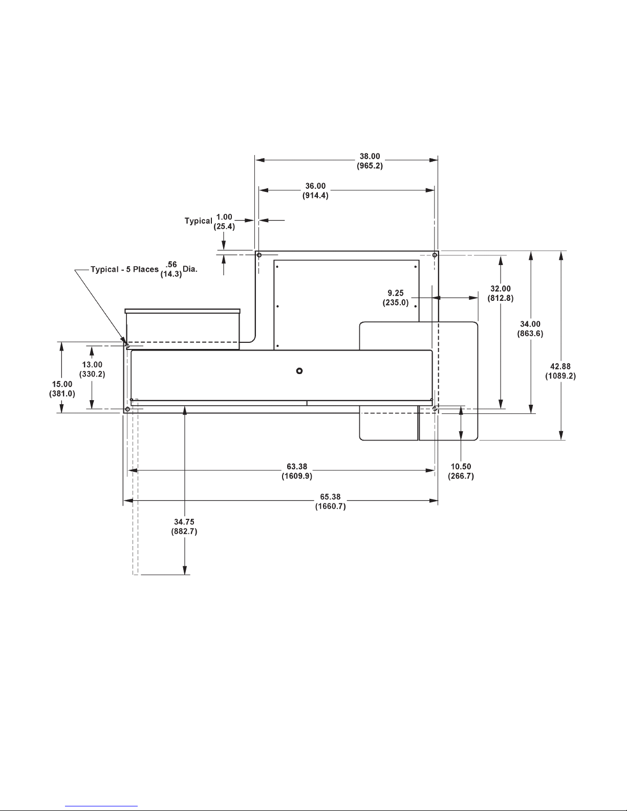
Floor Plan ............................................................... 1
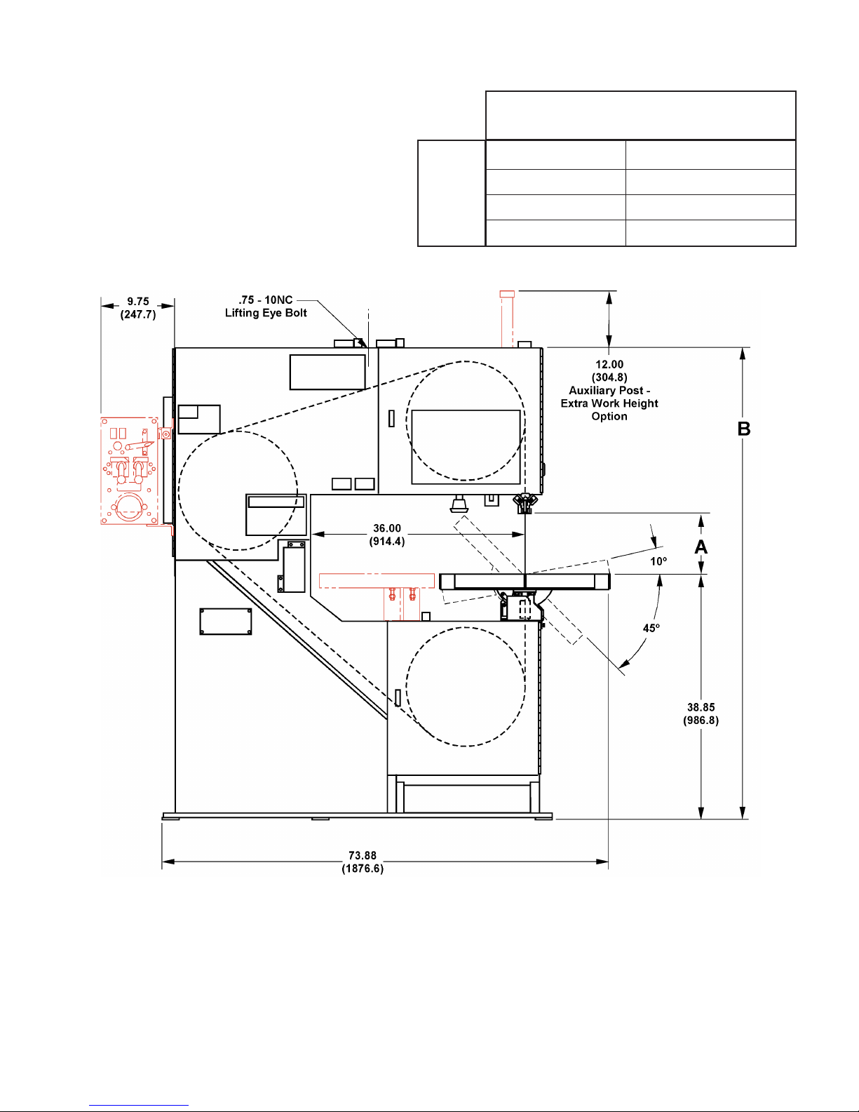
Front View .............................................................. 2
MACHINE FEATURES
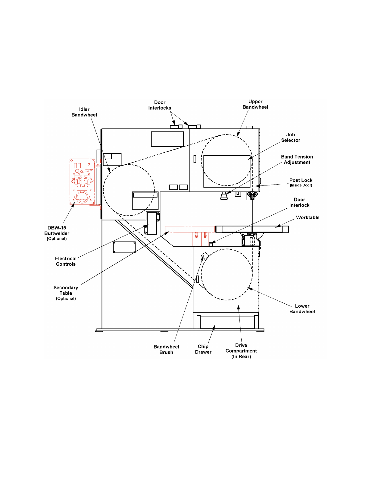
Front View .............................................................. 3
Rear View ............................................................... 4
INSTALLATION
Location .................................................................. 5
OSHA Notice!! ........................................................ 5
Unpacking ............................................................... 5
Cleaning ................................................................. 5
Lifting ...................................................................... 5
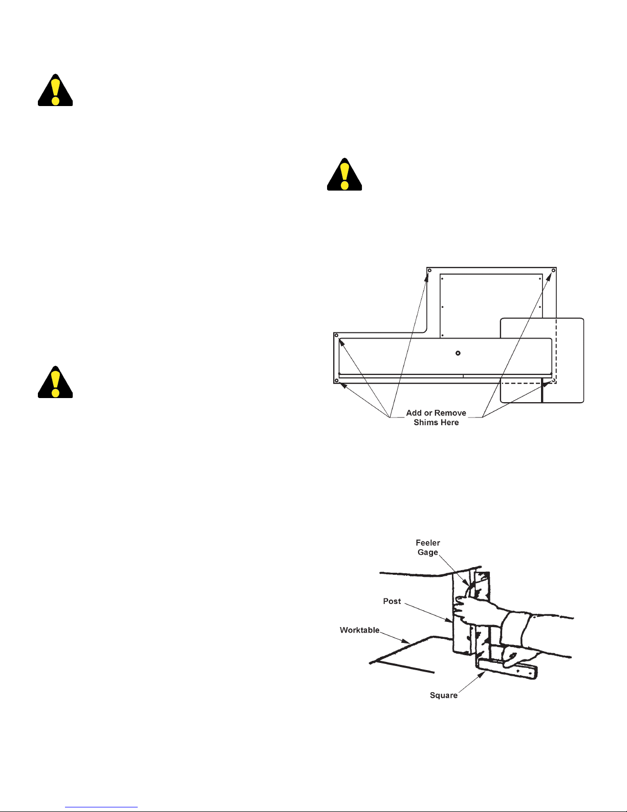
Machine Alignment ................................................. 5-6
Electrical Installation ............................................... 6
Preparation for Use ................................................ 6
OPERATION
Safety Precautions ................................................. 7
Using the Job Selector ........................................... 7
Electrical Controls ................................................... 8
Band Speed Controls ............................................. 8
Saw Band Preparation ............................................ 8-10
Post Adjustment ...................................................... 10
Worktable and Tilt Adjustment ................................ 10-11
Wheel Brush and Chip Removal ............................ 11
Typical Operation Procedures ................................ 11-12
LUBRICATION
Lubrication Chart .................................................... 14
Lubrication Diagram ............................................... 15
MAINTENANCE
Replacing Crowned Bandwheel Tires ..................... 16
Insert-Type Saw Guides ......................................... 16
Electric Motors ........................................................ 16
Head Components .................................................. 16
Spindle Drive Bearings ........................................... 16
Wheel Brush ........................................................... 16
Transmission .......................................................... 16
Variable Pulley ........................................................ 16
Band Drive Belt ....................................................... 16
Mist Coolant ............................................................ 16
Machine Cleaning ................................................... 16-17
TROUBLE SHOOTING .................................. 18-19
ACCESSORIES
Disc Cutter .............................................................. 20
Miter No. 2 Cut-Off (Side Mount) ............................ 20
Rip Fence ............................................................... 20
Heavy Work Slides ................................................. 20-21
Workholding Jaws .................................................. 21
Air-Operated Power Feed ....................................... 21
Chip Blower ............................................................ 22
Mist Coolant ............................................................ 22
Band Mist Lubricator ............................................... 22
Worklight ................................................................. 22
Magnier ................................................................. 22
Post Elevating Handwheel ...................................... 22
Worktable Options .................................................. 22-23
Air-Powered Worktable ........................................... 23
Universal Calibrated Work Fixture .......................... 23-24
Protractor Workstop and Alignment Gage .............. 24
DBW-15 Buttwelder ................................................ 24
Optional Saw Guides ..............................................24-26
90° Saw Guide Brackets ........................................ 26
Adjustable Angle Saw Guides ................................ 26
Dust Spout .............................................................. 26
Extra Work Height .................................................. 26
Band Filing .............................................................. 27
Band Polishing ........................................................ 28
Laser Line Generator Option .................................. 28

1
MACHINE DIMENSIONS
INCHES (± .03)
MILLIMETERS (± 1 mm)
FLOOR PLAN

2
MACHINE DIMENSIONS (Continued....)
INCHES (± .03)
MILLIMETERS (± 1 mm)
FRONT VIEW
13" (330.2 mm) 79.88" (2029.0 mm)
19" (482.6 mm) 85.88" (2181.4 mm)
25" (635.0 mm) 91.88" (2333.8 mm)
31" (787.4 mm) 97.88" (2486.2 mm)
AB
Dimensions
Work
Height

3
MACHINE FEATURES
FRONT VIEW

4
MACHINE FEATURES (Continued....)
REAR VIEW

5
INSTALLATION
All the “left”, “right”, “front” and “rear”
designations in this manual are as viewed by
the operator facing the machine's electrical
controls.
LOCATION
1. The oor area required by the standard machine is
approximately 73.88 inches (1876.6 mm) in width by
42.88 inches (1089.2 mm) in length. Machine height
for the standard machine is 79.88 inches (2029.0
mm). Refer to pages 1 & 2 for further machine
dimensions.
2. Locate the machine to provide adequate space
for your sawing needs. Be sure also to provide
sufcient clearance for loading and unloading of
stock, post elevation, door opening, maintenance
and lubrication procedures, plus operation of any
machine accessories.
OSHA NOTICE!!
OSHA Regulation 1910.212 (5B).
Machinesdesignedforaxedlocationshall
be securely anchored to prevent walking or
moving.
UNPACKING
1. The machine is fastened to and shipped on a wooden
skid. Overseas shipments are also crated.
2. Carefully remove all protective covers, strapping,
hold-down brackets, crating, etc. Then: (a) Remove
all bolts which fasten the machine to the shipping
skid; (b) Check inside the rear drive compartment
for other removable brackets, extra machine parts
or supplies which might have been placed there for
shipment; (c) Inspect the machine and all parts for
shipping damage. Claim procedures are listed on
this manual’s inside front cover.
CLEANING
1. If necessary, use solvent to remove rust-preventive
coating applied to exposed bare metal surfaces
before shipment.
LIFTING
1. A tapped hole is located on top of the machine's
saw head. Screw a forged 3/4-10NC eye-bolt into
this hole for lifting purposes. Gross weight of the
machine is approximately 1850 pounds (839.2
kg).
DO NOT lift the machine by its sawing head.
MACHINE ALIGNMENT
1. Place shims between the oor and the base mounting
pads until the machine weight is resting evenly on
all the base pads.
Typical Shim Locations.
2. Place a good quality, 10 inch (254.0 mm) master
square on the worktable against the post's back side.
Measure clearance between the post and square
near the bottom of the post. Clearance should be
within 0.007-inch ±0.005-inch (0.18 mm ±0.13 mm)
at the bottom of the post for standard machines.
Squaring Worktable to Post.

6
MACHINE ALIGNMENT (Continued....)
3. Square the worktable to the side of the post by
loosening the tilt lock bolt located in the machine's
frame under the worktable and make the necessary
adjustments. If necessary: (a) Position the
worktable's tilt angle pointer at zero (0) on the tilt
scale; (b) Tighten the tilt lock bolt.
4. Add or remove shims under the base pads until the
correct post to square clearance is obtained.
Themachinemustbeboltedtotheoorfor
worktable loads over 100 pounds (45.4 kg).
ELECTRICAL INSTALLATION
Electrical installation must be made by
authorized electrical maintenance personnel
only!
1. Refer to the machine specications plate on the
machine frame to verify that the electrical supply
circuit will meet the voltage/phase/frequency/
amperage requirements listed. A basic data plate
is reproduced on this manual’s introductory page.
2. Bring the incoming power leads into the machine's
electrical box. Refer to the electrical schematic, if
necessary, when making the connections.
3. Turn the disconnect switch on the electrical box to
ON. Then: (a) Alternately jog the Band Start and
Stop pushbutton; (b) Check to make sure the saw
band is running in a clockwise motion between the
saw guides; (c) Reverse the leads if the saw band
movement is incorrect.
PREPARATION FOR USE
1. Shop air is required to operate the optional chip
blower, mist coolant, sliding air table and/or band
lubricator. Incoming air supply should be between
80 and 90 psi (5.5 and 6.2 bar or 5.6 and 6.3 kg/
cm²).
DO NOT exceed 90 psi (6.2 bar or 6.3 kg/
cm²).
2. Check the optional mist coolant bottle (located on
the upper rear side of the saw head). Capacity is
one (1) quart (0.95 liters). Refer to the Lubrication
Chart for recommended lubricant.
4. Check the optional band mist lubricator unit for the
proper reservoir level. Refer to the manufacturer
supplied literature for reservoir capacity and
recommended procedures.
5. Make sure all other points listed by the Lubrication
Chart have been checked or properly serviced.

7
OPERATION
SAFETY PRECAUTIONS
Warning Label - READ and UNDERSTAND.
USING THE JOB SELECTOR
1. Refer to the Job Selector chart located on the
upper bandwheel door. It has information about the
recommended band type and pitch, band speeds
and cutting rates according to the type of material
to be cut and its thickness. It also has a radius
guide that shows the minimum radii cuts possible
with various saw band widths.
2. To use, nd the material to be cut in the rst column.
Then move to the right to nd information on coolant
application if any, band speed recommendations,
feed rates and band type and pitch.
The Job Selector is a guide only and the
recommendations shown can be adjusted to
meet special material requirements.
Job Selector.

8
ELECTRICAL CONTROLS
1. Foot Switch. Does not apply to this machine.
• Laser (Optional). This control turns the optional
laser line generator "OFF" and "ON".
2. Hydraulic. Not applicable when plugged.
3. Mist Lube (Optional). This switch turns the optional
band mist lubricator "OFF" and "ON".
4. Band Start/Stop. Push this upper green portion
of the button to start the band drive motor. Push
the lower red portion of the button to stop the band
drive motor.
Typical Electrical Control Box.
5. All Stop (Emergency Stop). Push this red
mushroom head button to stop all functions of the
machine. To resume operation, the button must be
reset by rotating the button head clockwise until
the head pops up.
Other Controls
1. Disconnect Switch. This switch, located on the
electrical control box enclosure, turns the supplied
incoming power to the machine "on" and "off".
2. Worklight (Optional). A switch on the worklight
turns the light "OFF" and "ON".
3. Controls for the optional DBW-15 Buttwelder are
described in a seperate instruction manual.
BAND SPEED CONTROL
1. The band speed control are located on the electrical
box mounted on the front of the machine.
2. Only the "high" speed set of numbers on the
escutcheon are used for your band speed range.
The "high" band speed range is 550 to 5500 fpm
(170 to 1675 m/min).
3. Variable speed is changed by turning the Band
Speed knob. Turn the control clockwise to
"increase" the band speed, counterclockwise to
"decrease" it.
4. During machine operation, keep the following band
speed precautions in mind:
Adjust the band speed only while the machine
is running.
Always turn the speed speed to its lowest
speed before stopping the machine.
Always allow the saw band to stop completely
before opening any bandwheel door.
SAW BAND PREPARATION
Saw Band Selection
1. The machine is equipped with an Imperial Bi-Metal
Super Silencer saw band that is 154 inches (3911.6
mm) long. It will accept saw band widths from 1/16
to one (1) inch (1.6 to 25.4 mm).
2. Standard equipment includes:
• One (1) set of high-speed, insert-type saw guide
blocks for saw bands from 1/16 to 1/2 inch (1.6 to
12.7 mm) wide.
• One (1) set of steel saw guide inserts for saw bands
1/4 to 1/2 inch (6.3 to 12.7 mm) wide.
Information about all DoALL saw bands can be
obtained from a DoALL sales representative.
Insert-Type Saw Guide Adjustment
These instructions apply to both the upper
and lower insert-type saw guide blocks.
Select the saw guide blocks and inserts marked for
the width of the saw band to be used. Then: (a)
Place the left insert in the left milled slot; (b) Tighten
the insert screw slightly so that the insert will slide
in the slot, yet still hold its correct position when
released.

9
2. Carefully slip the worn or broken saw band from
between the saw guide inserts and remove it from
around the bandwheels. Then work the saw band
out through the slot in the machine frame.
Saw Band Installation
Alwaysuseextremecarewhenhandlingsaw
bands. Wear gloves.
1. Remove the old saw band according to the directions
above. Then: (a) Place the new saw band carefully
through the slot in the machine frame; (b) Place the
new saw band carefully around the bandwheels and
between the upper and lower saw guide inserts; (c)
The saw band should track along the center of the
bandwheel tires.
2. Remove the new saw band's protective Saw Cap.
Then: (a) Apply the band tension recommended
by the scale adjacent to the tension adjustment
knob; (b) Reinstall the post saw band guard; (c)
Reposition and secure the worktable sawing slot
clamp bar; (d) Close all bandwheel doors.
Saw Band Tension Adjustment
1. Saw band tension is adjusted by turning the knob
located below the machine's sawing head (this knob
also is used to lock the post in place).
2. A scale showing the recommended tension for
various saw band widths is located to the right of the
tension adjustment knob. Scale numbers represent
the recommended tensions for common saw band
gages and pitches.
Adjusting Saw Band Tension.
3. The following are operator tensioning
recommendations:
• Reduce the recommended band tension when
using saw bands with a coarser pitch or lighter
gage.
• Increase the recommended band tension when
using heavier gage saw bands.
Positioning the Left Insert.
2. Select the insert gage which matches the size of the
saw band being used. Then: (a) Place the insert
gage in the right slot; (b) Adjust the left insert to t
exactly into the notched end of the gage; (c) Tighten
the left insert screw.
3. Place the right insert in its slot and tighten the
insert lightly. Then: (a) Place the gage edgewise
between both inserts; (b) Lower the right insert until
it rests against the gage; (c) Tighten the right insert
screw.
Positioning the Right Insert.
Insert-type saw guides are recommended
formaximumbandspeedsof1300fpm(390
m/min)forproductionsawing,orupto5000
fpm(1500m/min)foroccasionalsawing.Use
optional roller saw guides for continuous
sawingover1300fpm(390m/min).
Saw Band Removal
Alwaysuseextremecarewhenhandlingsaw
bands. Wear gloves.
1. Release saw band tension. Then: (a) Open all
bandwheel doors; (b) Remove the post saw band
guard; (c) Loosen the screw holding the worktable's
sawing slot clamp bar and move it aside; (d) Loosen
the saw guide inserts.
SAW BAND PREPARATION (Continued....)

10
Saw Band Tracking
1. The upper bandwheel can be tilted a maximum of
three (3) inches (76.2 mm) forward and backward
to help obtain correct saw band tracking. A saw
band is tracking properly when the saw band
center follows the center of both crowned rubber
bandwheel tires.
2. The following tracking procedures are to be
performed with the band drive motor off and the
transmission in "neutral": (a) Open both bandwheel
doors; (b) Manually turn the bandwheels to observe
how the saw band is tracking.
Tilt Adjustment Handles.
3. To adjust bandwheel tilt if tracking is not correct:
(a) Loosen the tilt lock handle; (b) Turn the tilt
adjustment handle until the saw band tracks
correctly on the bandwheel tires; (c) Retighten the
tilt lock handle.
4. Close both bandwheel doors.
POST ADJUSTMENT
1. Post and upper saw guide elevation can be adjusted
to accept workpieces with heights varying up to 13
inches (330.2 mm).
2. To adjust: (a) Loosen the lockscrew located inside
the upper bandwheel door by using the adjustment
knob and turn counterclockwise (this knob also
used for band tension adjustment); (b) Raise or
lower the post manually to the desired position; (c)
Turn the adjustment knob clockwise to lock the
post in position.
Post Adjustment.
3. Some machines have a optional post elevating
handwheel which uses a set of gears to raise and
lower the post. Refer to the "Accessories" section
for use of this option.
WORKTABLE AND TILT ADJUSTMENT
1. The standard worktable measures 26 by 26
inches (660.4 by 660.4 mm). Its load capacity is
500 pounds (226.8 kg) evenly distributed with NO
impact.
Themachinemustbeboltedtotheoorfor
table loads over 100 pounds (45.4 kg).
Worktable.
2. The worktable can be tilted manually up to 10º left
and 45º right primarily for sawing compound angles.
The amount of worktable tilt is indicated by a pointer
and a trunnion-mounted calibrated scale.
SAW BAND PREPARATION (Continued....)

11
3. To tilt the worktable: (a) Use the wrench provided
to reach through the machine frame and under
the worktable to loosen the tilt locknut; (b) Tilt
the worktable manually until the pointer reaches
desired angle shown on the scale; (c) Tighten the
tilt locknut.
4. The worktable is drilled and tapped on three (3)
sides to attach accessory equipment. Its removable
center plate can be replaced with optional plates for
band ling and band polishing and other various
options.
WHEEL BRUSH AND CHIP REMOVAL
1. A brush, located on the lower bandwheel
approximately in the ten (10) o'clock position, cleans
metal chips from the bandwheel during machine
operation. Removed chips drop into a removable
pan in the machine base. This pan should be
emptied periodically.
DO NOT open the bandwheel doors until saw
band has completely stopped.
2. During operation, chips and other depris may
accumulate around such machine areas as saw
guides, worktable surfaces, bandwheels, slides,
etc. Remove this debris as soon as possible. The
DoALL Company recommends removing chip
collections at least twice per each eight (8) hour
shift, and more often with heavier use.
TYPICAL SAWING PROCEDURES
Set-Up
1. These procedures assume that the following
machine conditions exist: (a) The machine has
been properly installed and aligned; (b) The band
drive motor is off; (c) The proper saw band has been
installed, is correctly tracked and tensioned; (d) All
lubrication procedures have been carried out.
Procedure
1. Raise the post high enough so that the upper saw
guide can not be damaged while stock is being
loaded onto the worktable.
2. Tilt the worktable to the desired angle and lock it in
place.
3. Load stock to be cut onto the worktable. Clamp the
stock if necessary.
4. Lower the post until the upper saw guide is just
above the stock, but NOT touching.
5. Determine the desired band speed for the procedure
to be undertaken. Then: (a) Push the Band Start
button; (b) Turn the Band Speed knob to the band
speed desired.
6. Carefully move the stock toward the saw band and
begin the cut. Adjust the band speed as necessary
during the cutting procedure.
7. After the cut has been nished: (a) Turn the Band
Speed knob to its lowest speed; (b) Push the Stop
button; (c) Remove the piece just cut from the
worktable; (d) Reposition the stock to begin another
cut; (e) Push the Band Start button and then set
the band speed.
Contour Sawing
1. Procedures for stock set-up and band speed
adjustment are the same as noted for production
sawing except that contour sawing of large, heavy
stock will require the use of optional air-operated
power feed or air-powered worktable and a heavy
gage saw band.
2. The following are important contour sawing
precautions which should be observed:
Reduce the feed force when cutting into an
opening to prevent saw band damage.
DO NOT feed work so rapidly that saw band
twisting or bowing occurs.
For future reference, keep a record of band
speed, feed pressure and coolant application
settings for successful jobs.
3. A hole is usually drilled in the stockpiece when a
sharp corner is to be cut, as shown in the illustration.
However, a corner may also be by-passed by cutting
a curve, and leaving the remainder to be notched
out later.
WORKTABLE AND TILT ADJUSTMENT
(Continued....)

12
Starting Hole for Sharp Contour Cutting.
Internal Contours
1. To prepare for internal contour sawing: (a) Drill a
starting hole in the stock; (b) Run the saw band
through the hole; (c) Weld the saw band. Insulate
the saw band from contact with the stock or the
worktable will insure a better weld.
2. The diameter of the drilled starting hole is determined
by the size of the saw band being used. Use the
widest possible saw band for cutting the curve.
Internal Contour Sawing.
3. Attempting to cut too small a radius with too wide
a saw band will cause binding, and the lower
bandwheel may become grooved. The chart on
the Job Selector shows minimum radii cuts possible
with various saw band widths.
TYPICAL SAWING PROCEDURES
Continued....)
4. Radii chart recommendations are based on sawing
relatively thin stock. Consider these variations: (a)
Use a heavy gage saw band for heavy stock sawing;
(b) Use a narrower than recommended saw band
when sawing stock more than one (1) inch (25.4
mm) thick.

13
LUBRICATION
NEXT 2 PAGES!

14
LUBRICATION
LUBRICATION CHART
LOCATION DESCRIPTION AND
SERVICE RECOMMENDATIONS
RECOMMENDED
LUBRICANT
LUBRICATION
INTERVAL*
LUBRICATION
POINT NO.
MONTHLY
MONTHLY
MONTHLY
CHECK
MONTHLY
MONTHLY
Post, Optional Post Elevating and Gears. Clean
and apply oil.
Band Tension Screw and Bearing. Clean and apply oil.
Bandwheel Slides, Hinges, and Tilt Screws.
Clean and apply oil.
Table Trunnion. Oil tilt surfaces.
Miscellaneous: Slides, Hinges, Pivot Points,
Component Parts, Unpainted Surfaces, etc. Clean and
apply oil as required.
Accessory Equipment as Supplied. Keep clean and
apply oil as required to maintain proper function, reduce
wear, and corrosion, etc.
High quality, rust and oxidation-inhibited,
medium hydraulic and general purpose
industrial oil.
ISO-VG Grade 68 (Formerly ASTM Grade
No. 315).
Union 76, UNAX RX 68, or equivalent.
1
2
3
4
5
6
CHECK
MONTHLY
High quality, EP (extreme pressure) multi-
purpose gear oil.
S.A.E. Grade No. 90.
Union 76, MP Gear Lube 90 or equivalent.
CHECK
MONTHLY
Spindle Drive Bearings. Two (2) bearings with grease
ttings.
7
Lubricate (if any) per manufacturer's recommendations.
Electric Motor. Band Drive.
Premium quality, saw band coolant and
lubricant.
DoALL cutting uids and/or oils (AL-2000).
Lubricate as required per DBW-15 Instruction Manual.
9
DBW-15 Buttwelder.
CHECK DAILY/
AS REQUIRED
Mist Coolant Reservoir (Optional). Keep lled and
hoses clear.
8
* Lubrication intervals are based on a 8-hour day, 40-hour week.
Lubricate more often with heavier use.
10 Band Mist Lubricator (Optional). Keep lled and
hoses clear.
11
Contact your DoALL sales representative
for the best oils and/or uids for your
application.
DoALL cutting uids and/or oils.
CHECK DAILY/
AS REQUIRED

15
LUBRICATION DIAGRAM
FRONT VIEW
REAR VIEW

16
REPLACING CROWNED BANDWHEEL TIRES
1. Loosen the worn tire with a screwdriver or other at
tool.
2. Stretch the tire if necessary to remove it.
3. Clean the bandwheel and install a new tire by
stretching it over the bandwheel.
INSERT-TYPE SAW GUIDES
Back-Up Inserts
1. Reverse back-up inserts for additional wear life,
then replace when all surfaces are worn.
Roller Back-Up Bearing
1. These bearings are sealed and packed for life with
a special lubricant. They can be replaced by: (a)
Removing the snap ring; (b) Pulling out the bearing
and shaft; (c) New bearings are easily installed with
a light press t.
ELECTRIC MOTORS
1. Follow the manufacturer's maintenance instructions
for each electric motor.
HEAD COMPONENTS
1. Wipe oil onto the post occasionally. Then move the
post up and down through the slide block several
times.
2. Oil the upper and idler bandwheel slides and band
tension screw each month.
3. Wheel bearings are sealed and lubricated for life.
SPINDLE DRIVE BEARINGS
1. THe spindle drive shaft has two (2) bearings with
grease ttings. Lubricate the bearings as necessary
according to the Lubrication Chart.
WHEEL BRUSH
1. Check the lower bandwheel brush occasionally for
correct position. Adjust the brush so it just touches
the bandwheel tire.
MAINTENANCE
Too much pressure of the brush will score the
bandwheel tire.
2. Replace the brush when necessary.
BAND DRIVE BELT
1. The belt driving the input sheave will stretch during
use. This stretch should be taken up by moving the
drive motor on its mounting plate.
2. To replace the belt: (a) Loosen the screws that
mount the drive motor and slide the motor to the
left; (b) Slip the old belt from the pulleys and install
the new one; (c) Slide the drive motor to the right
to tighten the belt so there is very little deection of
the belt; (d) When correct belt tension is acheived,
tighten the screws.
4. Tension the belt by loosening the motor mounting
bolts, slide the motor to the right until correct tension
is obtained and then tighten the bolts.
MIST COOLANT (If Supplied)
1. Intermittent coolant stream indicates an air leak.
Check all joints.
2. Clogging may occur if waxed-based or other
coolants are used. Your DoALL sales representative
can provide complete information about various
coolants.
3. Keep the mist applicator nozzle and lter clean.
If the center nylon coolant tube needs replacing,
remove the entire applicator tube. Insert new nylon
tube and trim off excess ush with nozzle. Make
sure all joints are sealed and tight after applicator
tube is reinstalled.
MACHINE CLEANING
Stop the machine when cleaning the machine
or opening bandwheel doors or covers.
1. Keep the machine and its parts as clean as possible
to prevent excessive wear and damage.
2. Remove the chip drawer and dispose of the chips
when necessary.
Table of contents
Other DoAll Saw manuals

DoAll
DoAll DS-320SA User manual

DoAll
DoAll 2613-V3 User manual

DoAll
DoAll C-530 M Technical reference manual

DoAll
DoAll C-260 NC Parts list manual

DoAll
DoAll c-530 nc Parts list manual

DoAll
DoAll C-8056SA User manual

DoAll
DoAll 800SNC User manual

DoAll
DoAll 500SNC User manual

DoAll
DoAll C-916S User manual

DoAll
DoAll C-4100NC User manual
Popular Saw manuals by other brands

pistorius
pistorius MN100 operating instructions

Erbauer
Erbauer ERB609MSW Original instructions

Tractive
Tractive Pentruder 8-20iQ Operator's manual

Bosch
Bosch GSA 10,8 V-LI Professional Original instructions

Craftsman
Craftsman CMCS351 instruction manual

Sparky Group
Sparky Group HD PROFESSIONAL TSB 1300C Original instructions