DoAll C-4033NC User manual

Utility Line
Models:
Metal Cutting
Band Sawing Machine
May 2018
C-3028NC/BOXED
C-4033NC
C-420NC/BOXED
C-5650NC
C-560NC
C-6260NC
Instruction Manual


i
OPERATOR’S INSTRUCTION MANUAL
METAL CUTTING BAND SAW
For your information and future reference, pertinent data concerning your machine should be written
in the spaces provided above. This information is stamped on a plate attached to your machine. Be
sure to provide machine model and serial number with any correspondence or part orders.
Specifications contained herein were in effect at the time this manual was approved for printing. The
DoALL Company, whose policy is one of continuous improvement, reserves the right, however, to
change specifications or design at any time without notice incurring obligations.
PLEASE READ THIS MANUAL CAREFULLY BEFORE OPERATING THE MACHINE!
For sales, parts and service call +31 78 652 6060, or e-mail info@doall.nl
For general information, please visit our website at: www.doall.nl
DoALL Europa B.V.
Debijestraat 14
3316GE Dordrecht, NL
The following registered trademarks of the DoALL Company are used in this manual: DoALL.
PRINTED IN THE NETHERLANDS

ii
TABLE OF
CONTENTS
SAFETY RULES .......................................... 1
MACHINE SPECIFICATIONS .................. 2-3
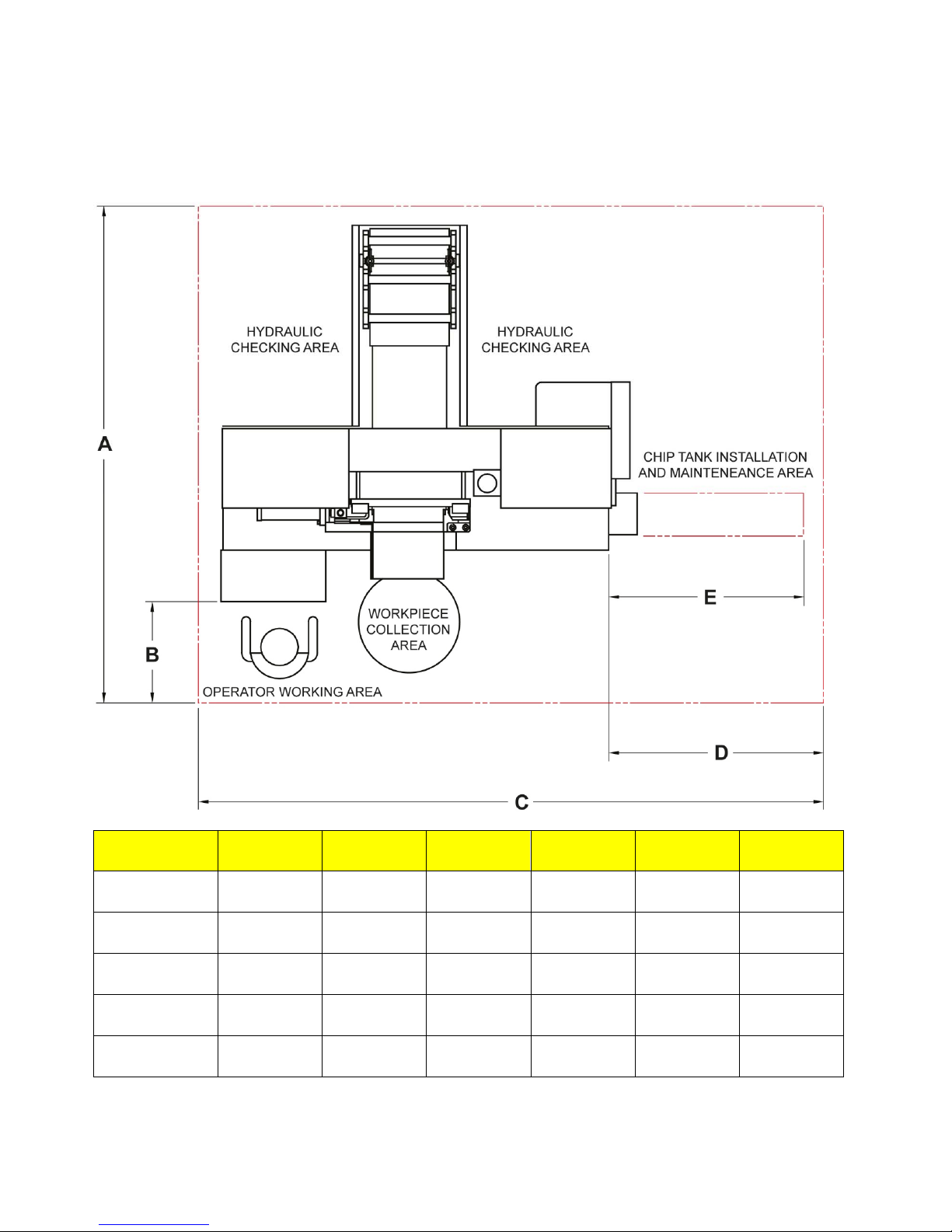
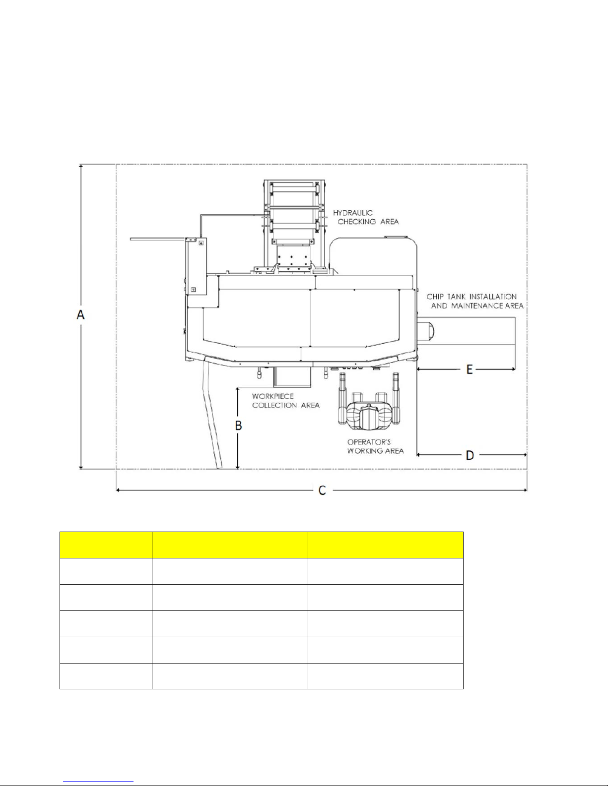
MACHINE DIMENSIONS
Installation dimensions .............................. 4-5
C-3028NC dimensions ................................. 6
C-3028NC Boxed dimensions ...................... 7
C-4033NC dimensions ................................. 8
C-420NC dimensions ................................... 9
C-420NC Boxed dimensions ...................... 10
C-5650NC dimensions ............................... 11
C-560NC dimensions ................................. 12
C-6260NC dimensions ............................... 13
MACHINE FEATURES .............................. 14
INSTALLATIONS
Locations.................................................... 15
OSHA Notice .............................................. 15
Unpacking .................................................. 15
Lifting ......................................................... 15
Cleaning ..................................................... 16
Floor installation ......................................... 16
Electrical installation .................................. 16
Preparation for use .................................... 17
OPERATION
Selecting band speed and cutting rate ....... 18
Control console .................................... 19-21
Operator workstation ............................. 21-25
Setup for creating jobs .......................... 25-26
Machine preparation ............................. 26-27
Band speed range ...................................... 27
Left saw guide arm adjustment .................. 27
Feed force adjustment .......................... 27-28
Feed rate ................................................... 28
Head elevation and sensing arm ............... 28
Minimum bar end ....................................... 28
Vertical guide rollers .................................. 29
Hydraulic system ....................................... 29
Coolant system ......................................... 29
Chip removal ......................................... 29-30
Nesting fixture ....................................... 30-31
Typical operating procedures ................ 31-32
LUBRICATION
Lubrication chart ........................................ 33
Lubrication diagrams.................................. 34
MAINTENANCE
Replacing saw guide and backup inserts ... 35
Band/brush drive belt replacement ............ 35
Hydraulic system ....................................... 35
Coolant system .......................................... 35
Band drive gear box ................................... 36
Machine cleaning ....................................... 36
Machine alignment ..................................... 36
Band brush ................................................ 36
Band tension measurement ....................... 36
Wear plate replacement ........................ 36-37
Band wheels .............................................. 37
Cleaning chip conveyor .............................. 37
TROUBLE SHOOTING ........................ 38-40

1
SAFETY RULES
1. CLOTHING. To protect from
entanglement or being pulled by a
clamped vise, the operator should not
wear loose fitting clothing or wear
gloves while operating the machine.
Wear safety shoes to protect against
foot injury.
2. INSTALLATION. The machine must be
properly grounded to protect against
electric shock. Use durable insulating
material to protect power lines that lie
on the floor.
3. DO NOT defeat the purpose of any
guards or any other safety devices.
THEY ARE THER FOR YOUR
PROTECTION.
4. Keep hands away from moving saw
blade while running the machine.
5. If the operator needs to check the
interior of the machine during operation,
turn the machine off and wait until the
machine comes to a complete stop.
6. DO NOT enter the index vise moving
area. Lifting of workpieces to the
feeding table is done by overhead hoist.
7. DO NOT touch the circuit breakers,
switches or buttons with wet hands.
8. Turn power off before servicing,
cleaning or maintenance.
9. Wear gloves when replacing the saw
blade, removing chips, replacing cutting
fluid or when moving material.
10. Coolant is no edible. If swallowed,
immediately spit it out and rinse the
mouth thoroughly.
11. DO NOT operate, maintain or check the
machine under the influence of alcohol
or medication.
12. The machine will stop when a door or
guard is opened. Wait until the machine
comes to a complete stop before
entering the area.
13. DO NOT stand on the front or rear
supporting rollers.
14. Periodically perform a machine check
before starting. After completing a job,
clean both the machine and the work
area thoroughly.
15. The machine operator must be trained
and must understand the operation,
lifting, saw blade replacement and
maintenance of the machine.
16. Maintenance personnel must be trained
and knowledgeable of electrical control
systems.
17. This machine is designed to cut steel
bars and profiled tubes only. Do not cut
food, wood, plastic, poisonous material,
magnesium or its alloys.

2
MACHINE SPECIFICATIONS
Specification C-3028NC C-3028NC
Boxed
C-4033NC C-420NC
Cutting
Capacity
Rounds 10
–
280 mm 10
–
280 mm 10
–
330vmm 10
–
420 mm
Rectangles
W x H
10 x 10 –
300 x 280
mm
10 x 10 –
300 x 280
mm
10 x 10 –
400 x 330
mm
10 x 10 –
420 x 420
mm
Bundle
Cutting
Minimum
W x H
165 x 15 mm 165 x 15 mm 165 x 50 mm 165 x 80 mm
Maximum
W x H
250 x 100
mm
250 x 100
mm
370 x 170
mm
370 x 200
mm
Band Saw Blade 3.820x34x1,1
mm
3.820x34x1,1
mm
4242x34x1,1
mm
4.880x41x1,3
mm
Band Speed Low Range 18 – 85
m/min
18 – 85
m/min
18 – 85
m/min
18 – 85
m/min
High Range 25 – 135
m/min
25 – 135
m/min
25 – 135
m/min
25 – 135
m/min
Band Drive Moto
r
3,7 KW 3,7 KW 3,7 KW 5,5/7,5 KW
Main Drive Belt 3V425X2 3V425X2 3V425X2 3V530X2
Band Brush Belt M40 M40 M40 M46
H
y
draulic Pump Moto
r
0,75 KW 0,75 KW 0,75 KW 0,75 kW
Coolant Pump Moto
r
0,18 KW 0,18 KW 0,18 KW 0,18 KW
Band Drive Gear Capacit
y
6 ℓ 6 ℓ 7ℓ 11,5 ℓ
H
y
draulic Tank Capacit
y
60 ℓ 60 ℓ 60 ℓ 85 ℓ
Coolant Tank Capacit
y
80 ℓ 80 ℓ 90 ℓ 100 ℓ
Index
Length
Sin
g
le 400 mm 400 mm 500 mm 500 mm
Multiple 8.000 mm 8000 mm 8.000 mm 8.000 mm
Dimensions W x H x L 2100 x1300
x1990 mm
2405 x 1740
x 2010 mm
2250 x 1400
x 2195 mm
2450 x 1665
x 2235 mm
Workin
g
hei
g
ht 700 mm 700 mm 700 mm 700 mm
Conve
y
or Len
g
th 2000 mm 2000mm 2000mm 2000mm
Conve
y
or Width 452 mm 452 mm 576 mm 625 mm
Conve
y
or Hei
g
ht 710 mm 710 mm 720 mm 720 mm
Conve
y
or Load 2250 k
g
/M 2250 k
g
/M 2550 k
g
/M 3500 k
g
/M
Net wei
g
ht 1.750 k
g
1950 k
g
2.000 k
g
2.450 k
g
Electrical Power Connection 5 KW 5KW 5 KW 8 KW

3
MACHINE SPECIFICATIONS (continued)
Specification C-420NC
Boxed
C-5650NC C-560NC C-6260NC
Cutting
Capacity
Rounds 10
–
420 mm 10
–
500 mm 10
–
560 mm 10
–
600 mm
Rectangles
W x H
10 x 10 –
420 x 420
mm
10 x 10 –
560 x 500
mm
10 x 10 –
610 x 560
mm
10 x 10 –
620 x 600
mm
Bundle
Cutting
Minimum W x H 165 x 80 mm 240 x 80 mm 250 x 145
mm
250 x 145
mm
Maximum W x H 370 x 200
mm
480 x 240
mm
505 x 225
mm
505 x 225
mm
Band Saw Blade 4880x41x1,3
mm
5450x41x1,3
mm
6.600x54x1.6
mm
6560x41x1,3
mm
Band
Speed
Low Range 18 – 85
m/min
18 – 85
m/min
18 – 85
m/min
18 – 85
m/min
High Range 25 – 135
m/min
25 – 135
m/min
25 – 135
m/min
25 – 135
m/min
Band Drive Moto
r
5,5 / 7,5 KW 5,5 KW 7,5 KW 5,5 KW
Main Drive Belt 3V530X2 3V530X2 3V530X2 3V530X2
Band Brush Belt M46 M46 M56 M56
H
y
draulic Pump Moto
r
1,5 kW 1.5 kW 2,25 KW 1,5 KW
Coolant Pump Moto
r
0,18 KW 0,18 KW 0,18 KW 0,18 KW
Band Drive Gearbox Capacit
y
11,5 ℓ 18 ℓ 28 ℓ
H
y
draulic Tank Capacit
y
85 ℓ 85 ℓ 130 ℓ 85 ℓ
Coolant Tank Capacit
y
100 ℓ 110 ℓ 140 ℓ 150 ℓ
Index
Length
Sin
g
le 500 mm 500 mm 400 mm 400 mm
Multiple 8.000 mm 8.000 mm 8.000 mm 8000 mm
Dimensions W x H x L 2790 x 1970
x 2270 mm
2630 x 1820
x 2260 mm
3280 x 2160
x 2125 mm
3120 x 2030
x 2130
Workin
g
Hei
g
ht 700 mm 750 mm 850 mm 800 mm
Conve
y
or Len
g
th 2000 mm 2000 mm 2000 mm 2000 mm
Conve
y
or Width 625 mm 745 mm 855 mm 820 mm
Conve
y
or Hei
g
ht 720 mm 830 mm 870 mm 830 mm
Conve
y
or Load 3500 k
g
/M 4150 k
g
/M 6000 k
g
/M 4000 k
g
/M
Net wei
g
ht 2800 k
g
3100 k
g
4.500 k
g
3800 k
g
Electrical Power Connection 8 / 12 KW 8 KW 12 KW 8 KW

4
MACHINE DIMENSIONS
INSTALLATION DIMENSIONS
Dimensions
C-3028NC C-4033NC C-420NC C-5650NC C-560NC C-6260NC
A
2.750 mm 2.980 mm 2.980 mm 3.000 mm 2.850 mm 2850 mm
B
600 mm 600 mm 600 mm 600 mm 600 mm 600 mm
C
3.160 mm 3.420 mm 3.680 mm 3.980 mm 4.760 mm 4700 mm
D
1.060 mm 1.170 mm 1.265 mm 1.370 mm 1.600 mm 1600 mm
E
950 mm 1.050 mm 1.150 mm 1.250 mm 1.450 mm 1450 mm

5
MACHINE DIMENSIONS
INSTALLATION DIMENSIONS (continued)
Dimensions
C-3028NC Boxed C-420NC boxed
A
2940 mm 3270 mm
B
790 mm 830 mm
C
3950 mm 4355 mm
D
1060 mm 1095 mm
E
950 mm 950 mm

6
MACHINE DIMENSIONS (Continued…)
C-3028NC DIMENSIONS

7
MACHINE DIMENSIONS (Continued…)
C-3028NC (Boxed ) DIMENSIONS

8
MACHINE DIMENSIONS (Continued…)
C-4033NC DIMENSIONS

9
MACHINE DIMENSIONS (Continued…)
C-420NC DIMENSIONS

10
MACHINE DIMENSIONS (Continued…)
C-420NC (BOXED) DIMENSIONS

11
MACHINE DIMENSIONS (Continued…)
C-5650NC DIMENSIONS

12
MACHINE DIMENSIONS (Continued…)
C-560NC DIMENSIONS

13
MACHINE DIMENSIONS (Continued…)
C-6260NC DIMENSIONS

14
MACHINE FEATURES

15
INSTALLATION
All the left, right, front and rear
designations in this manual are as
viewed by the operator facing the
control console.
LOCATION
1. Locate the machine to provide sufficient
clearance for: (a) material loading and
unloading; (b) all door openings; (c) head
elevation; (d) chip conveyor removal; (e)
maintenance and lubrication procedures; (f)
operation and supplied machine accessories.
2. Accessories such as roller stock conveyors will
require additional work space.
OSHA NOTICE
OSHA regulation 1910.212(5B). Machines
designed for a fixed location shall be
securely anchored to prevent walking or
moving.
UNPACKING
1. The machine is fastened to and shipped on a
wooden skid. Overseas shipments are also
crated.
2. Remove all protective covers, strapping, crating,
etc. Then: (a) remove all bolts which fasten the
machine to the shipping skid; (b) do not remove
the shipping bracket that attaches the saw head
to the vise base yet; (c) remove any loose items
and boxes that may have been placed on the
machine; (d) inspect the machine and all parts
for shipping damage. Claim procedures are
listed on the manual’s inside front cover.
LIFTING
NEVER lift the machine by its sawing head.
1. The chart below shows the recommended
capacities for lifting the machine.
C-3028NC C-4033NC C-420NC
Crane 3 Ton 3 Ton 4 Ton
Fork lift 3 Ton 3 Ton 4 Ton
C-5650NC C-560NC C-6260NC
Crane 5 Ton 6 Ton 6 Ton
Fork lift 5 Ton 8 Ton 7,5 Ton
2. Four (4) permanent lifting eye lugs are provided
for machine lifting purposes: (a) two (2) lifting
lugs are located at the rear of the index vise
roller table; (b) two (2) other lifting lugs are
located on the machine’s front left and right
corners.
Lifting by overhead hoist.
3. Using chains or heavy duty straps attached to
the lifting lugs, it is recommended that lifting and
transporting of the machine be done with an
overhead hoist.
4. It is also recommended to protect painted
surfaces from damage due to the lifting chains
coming into contact with the machine surface.
5. If a fork lift truck is used, make sure it has
appropriate capacity to lift the machine safely.
It is recommended that you lift the machine from
the front as shown.
Lifting by fork lift truck.
6. Roller stock conveyors can be lifted and
transported by overhead hoist, fork lift, or by
other means that provide adequate safety
precautions.
This manual suits for next models
7
Table of contents
Other DoAll Saw manuals

DoAll
DoAll C-820 M Parts list manual

DoAll
DoAll ZV-3620 User manual

DoAll
DoAll C-520NC User manual

DoAll
DoAll TF-2525 User manual

DoAll
DoAll c-530 nc Parts list manual

DoAll
DoAll C-8056SA User manual

DoAll
DoAll 800SNC User manual

DoAll
DoAll c-530 nc User manual

DoAll
DoAll C-260 NC Parts list manual

DoAll
DoAll 500SNC User manual