ii
TABLE OF CONTENTS
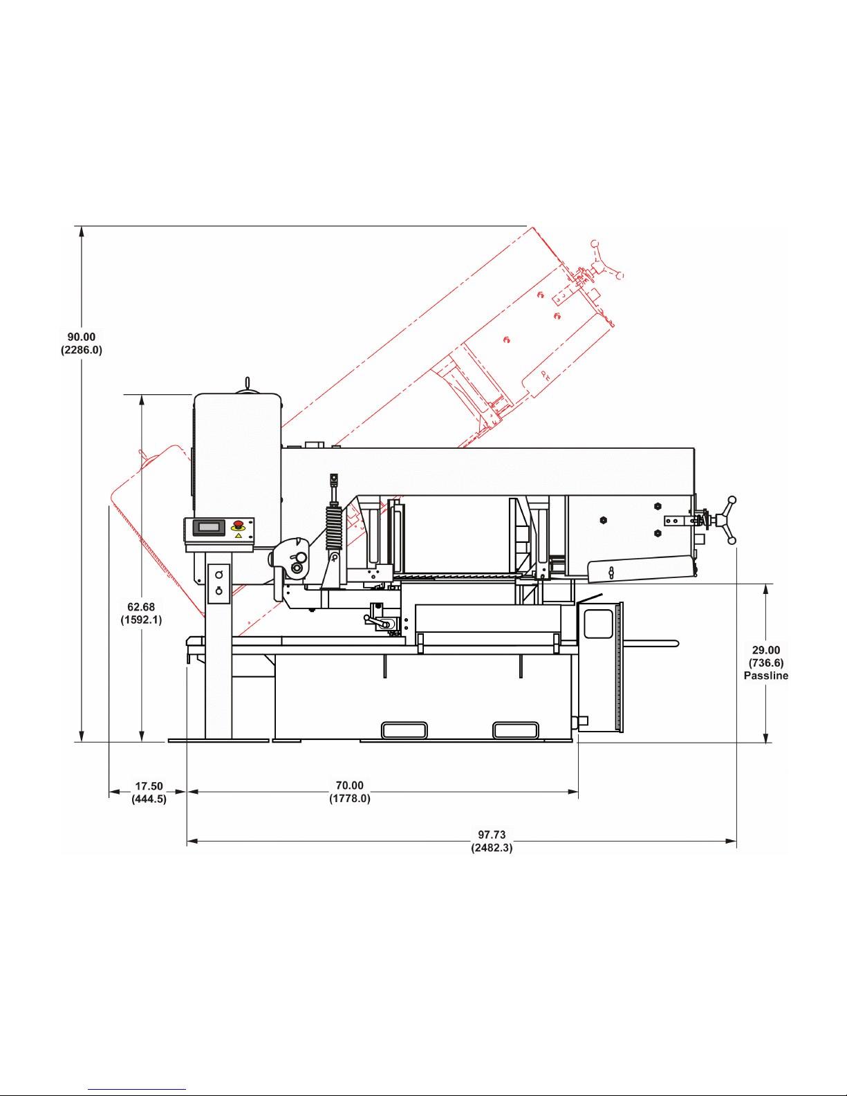
MACHINE DIMENSIONS
Floor Plan .................................................... 1
Top View ................................................................. 2
Front View .............................................................. 3
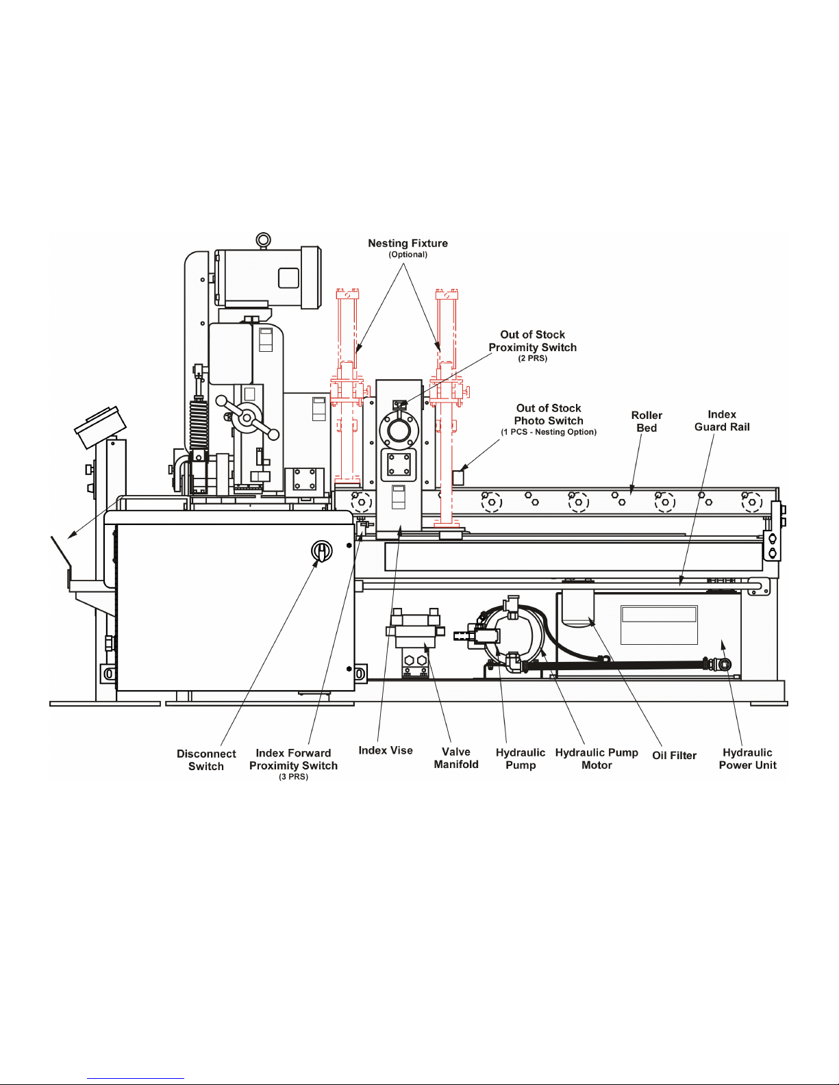
MACHINE FEATURES
Front View ................................................... 4
Rear View ............................................................... 5
Side View ................................................................ 6
INSTALLATION
Location .................................................................. 7
OSHA Notice!! ........................................................ 7
Unpacking ............................................................... 7
Cleaning ................................................................. 7
Lifting ...................................................................... 7
Floor Installation ..................................................... 7-8
Electrical Installation ............................................... 8
Plant Air Installation ................................................ 8
Preparation for Use ................................................ 8
OPERATION
Safety Precautions ................................................. 9
Using the Saw Band Selector ................................. 9
Cutting Capacity ..................................................... 9
Machine Controls .................................................... 9
Operator Workstation ............................................. 10-14
Saw Band Preparation ............................................ 14-16
Saw Guide Arm Adjustment .................................... 16
Work Height Adjustment ......................................... 16
Saw Head Positioning for Angle Cuts ..................... 16
Flood Coolant System ............................................ 17
Dry Cutting .............................................................. 17
Band Brush and Chip Removal .............................. 17-18
Typical Operation Procedures ................................ 18-19
LUBRICATION
Lubrication Chart .................................................... 20
Lubrication Diagrams .............................................. 21
MAINTENANCE
Saw Guide Insert Replacement .............................. 22
Drive Belt Removal or Replacement ...................... 22
Band Tension Adjustment ....................................... 23
Flood Coolant ......................................................... 23
Chip Removal ......................................................... 23
Replacing Vise Bed Wear Plates ............................ 23
Bandwheels ............................................................ 23-24
Counterbalance Spring ........................................... 24
Electic Motors ......................................................... 24
Mist Lubricator ........................................................ 24
TROUBLE SHOOTING .................................. 25-28
ACCESSORIES
Roller Stock Conveyors .......................................... 29
Vertical Guide Rollers (For Conveyors) .................. 29
Nesting Fixture ....................................................... 29-30
Variable Vise Pressure ........................................... 30
Worklight ................................................................. 30
Laser Line Option ................................................... 30-31
Band Mist Lubricator ............................................... 31
ii
How to read your serial number: