DoAll TF-2525 User manual

BAND SAWING MACHINE
INSTRUCTION
MANUAL
MODEL: TF-2525
SERIAL NO: 356-76101 to 356-01282
Also Applies To Machines With A
“Tf-25SA” Designation.

DAMAGE CLAIM PROCEDURES
VISIBLE DAMAGE AT THE TIME OF DELIVERY:
1. Note damage on carrier’s delivery receipt. Accept the shipment. It can be returned later if repairs
are not possible in the eld.
2. Request a “damage inspection” from the delivery carrier:
a. The carrier will send his own people or contract an independent agency to make the
inspection.
b. The inspector will request a signature on the report and leave a copy.
c. The carrier “damage inspection” report is not nal. If additional damage is found when
repairs are started, contact the carrier for another inspection; or at least give them the
details of the damage.
3. Do not move the equipment from the receiving area and keep all shipping materials until carrier
“damage inspection” report is complete.
4. If possible, take photographs of the damage and keep them for your les. Photos could possibly
prove a claim at a later time.
5. Keep a record of all expenses and be sure they are documented.
6. Repair damage in the eld whenever possible. Carriers encourage this to keep expenses down.
7. You have nine (9) months to le a claim.
1. You have fourteen (14) days to report damage not noted at time of delivery.
a. Report damage as soon as possible. This makes it easier to prove that it did not happen
at cosignee’s plant.
b. Inspect machine(s) carefully before moving from the receiving area. Again, if machine is
not moved, it is easier to prove your case.
2. Request a “damage inspection” from the delivery carrier:
a. The carrier will send his own people or contract an independent agency to make the
inspection.
b. The inspector will request a signature on the report and leave a copy.
c. The carrier “damage inspection” report is not nal. If additional damage is found when
repairs are started, contact the carrier for another inspection; or at least give them the
details of the damage.
3. Do not move the equipment from the receiving area and keep all shipping materials until carrier
“damage inspection” report is complete.
4. If possible, take photographs of the damage and keep them for your les. Photos could possibly
prove a claim at a later time.
5. Keep a record of all expenses and be sure they are documented.
6. Repair damage in the eld whenever possible. Carriers encourage this to keep expenses down.
7. You have nine (9) months to le a claim.
CONCEALED DAMAGE:

i
OPERATOR'S INSTRUCTION MANUAL
UNIVERSAL TILT-FRAME BAND MACHINE
MODEL FIRST SERIAL NO. LAST SERIAL NO.
TF-2525 356-76101 356-01282
PRINTED IN U.S.A. PB-331.5 (12-07)
Also applies to machines with "TF-25 SA" designation.
For your information and future reference, pertinent data concerning your
machine should be written in the spaces provided above. This information is
stamped on a plate attached to your machine. Be sure to provide machine
model and serial numbers with any correspondence or parts orders.
Specications contained herein were in effect at the time this manual was
approved for printing. The DoALL Company, whose policy is one of continuous
improvement, reserves the right, however, to change specications or design
at any time without notice and without incurring obligations.
The following registered trademarks of the DoALL Company are used in this manual:
DoALL, Imperial Bi-Metal, Polypac and Tensigage.
DoALL SAWING PRODUCTS
2375B TOUHY AVENUE
ELK GROVE, ILLINOIS 60007 U.S.A.
PLEASE READ THIS MANUAL CAREFULLY BEFORE OPERATING THE MACHINE!
For Sales, Parts and Service, call1-888-362-5572

ii
TABLE OF CONTENTS
LUBRICATION
Lubrication Chart .................................................... 22
Lubrication Diagram ............................................... 23
MAINTENANCE
Replacing Saw Guide and Back-Up Inserts ........... 24
Hydraulic System .................................................... 24-25
Coolant Ststem ....................................................... 25
Machine Cleaning ................................................... 25
Machine Alignment ................................................. 25
Brush Adjustments .................................................. 25
Wear Plate Replacement ........................................ 25
Bandwheels ............................................................ 26
Chip Conveyor ........................................................ 26
Miter Meter ............................................................. 26
TROUBLE SHOOTING .................................. 27-29
ACCESSORIES
Variable Vise Pressure ........................................... 30
Filler Plates ............................................................. 30
Nesting Fixture ....................................................... 30-31
Roller Stock Conveyors .......................................... 31-32
Workstop ................................................................ 32
Vertical Guide Rollers ............................................ 32
Mist Lubricator ........................................................ 32
Right Hand Vise ...................................................... 32
Lift Rollers ............................................................... 32
Laser Line Option ................................................... 33
Fixed Frame (Non-Tilting) ....................................... 33
Extra Work Height .................................................. 33
Band Twist Indicator ............................................... 33-34
Medium Torque Drive ............................................. 34
Saw Band Modication ........................................... 34
Head Travel Indicator ............................................. 34
Reinforcing Legs (Heavy Work Support) ................ 34
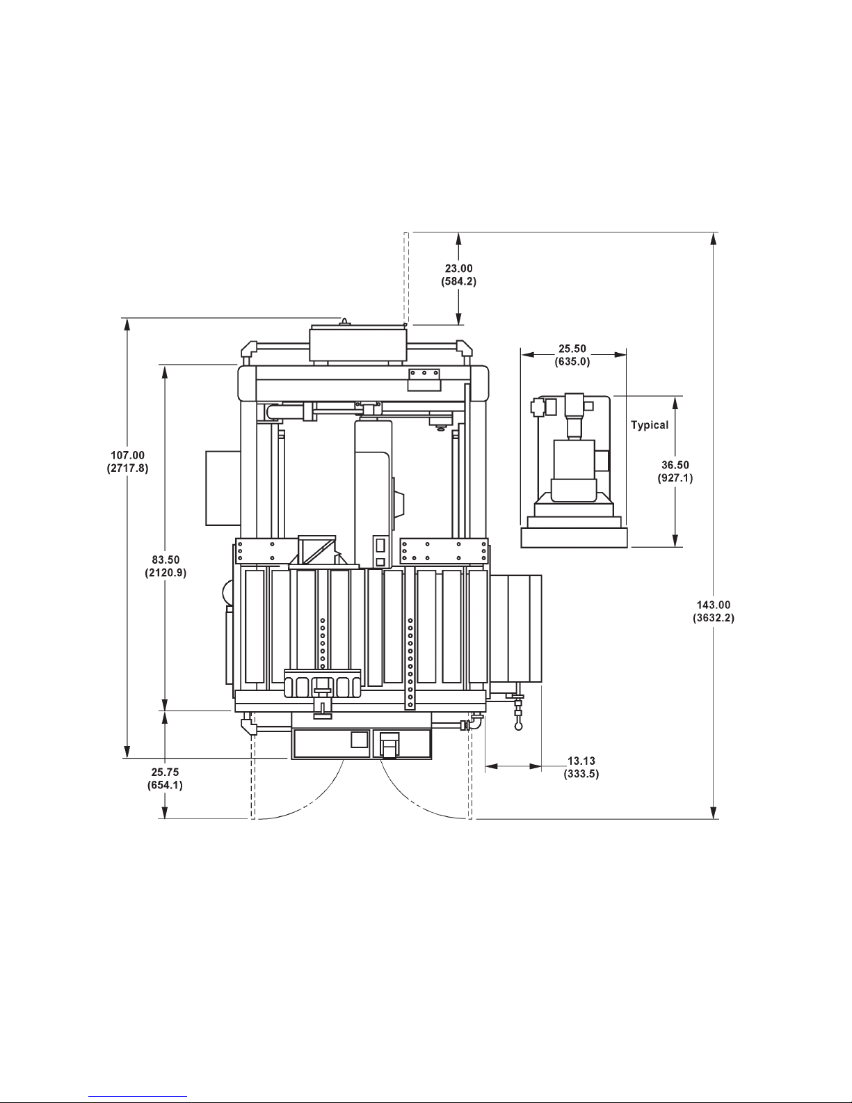
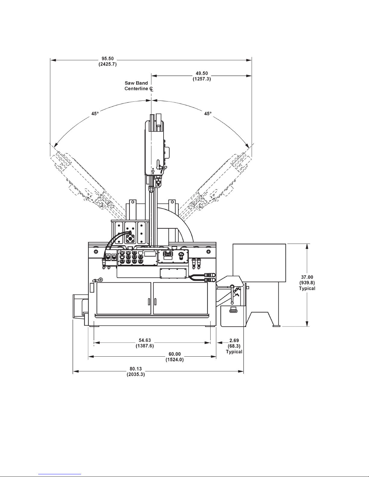
MACHINE DIMENSIONS
Floor Plan ............................................................... 1
Front View .............................................................. 2
Side View ................................................................ 3
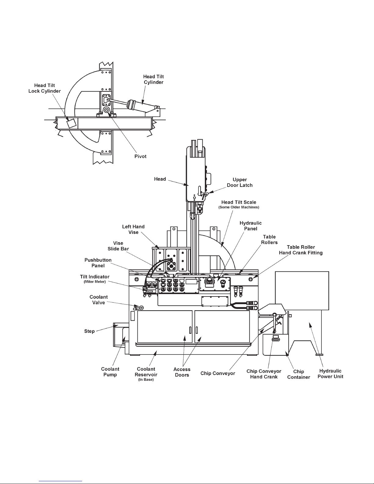
MACHINE FEATURES
Front and Rear Views ............................................. 4
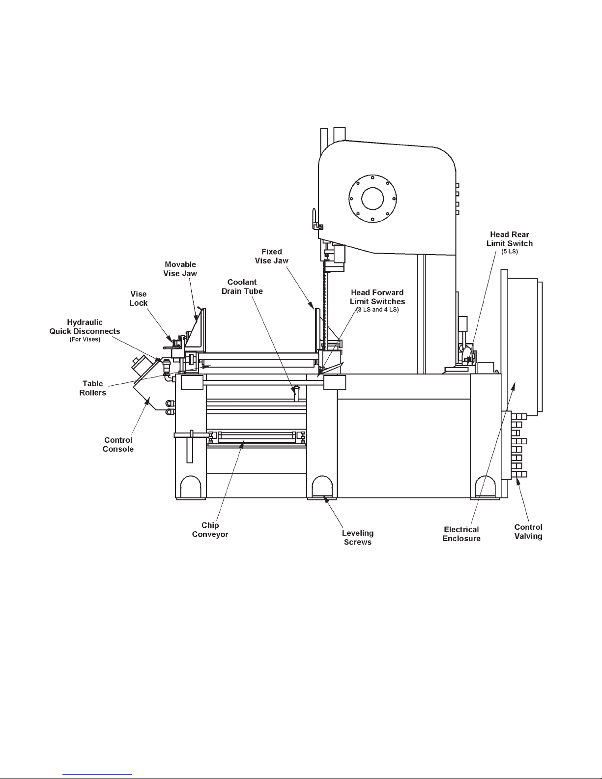
Side View ................................................................ 5
Head Assembly ....................................................... 6
INSTALLATION
Location .................................................................. 7
OSHA Notice!! ........................................................ 7
Unpacking ............................................................... 7
Cleaning ................................................................. 7
Lifting ...................................................................... 7
Floor Installation and Alignment ............................. 7
Electrical Installation ............................................... 8
Hydraulic Installation .............................................. 8
Coolant Installation ................................................. 9
Preparation for Use ................................................ 9
OPERATION
Safety Precautions ................................................. 10
Using the Job Selector ........................................... 10
Cutting Capacity ..................................................... 11
Control Console ...................................................... 11-14
Saw Band Preparation ............................................ 14-15
Post Adjustment ...................................................... 15
Head Reverse Rate ................................................ 16
Head Tilt Adjustments ............................................. 16
Miter Meter ............................................................. 16
Roller Table ............................................................. 16
Vise Adjustments .................................................... 16-17
Band Feed Adjustments ......................................... 17
Coolant System ..................................................... 18
Hydraulic System .................................................... 18
Chip Removal ......................................................... 18-19
Typical Operation Procedures ................................ 19-20
How to read your serial number:

1
MACHINE DIMENSIONS
FLOOR PLAN
INCHES (± .03)
MILLIMETERS (± 1 mm)

2
MACHINE DIMENSIONS (Continued....)
FRONT VIEW

3
INCHES (± .03)
MILLIMETERS (± 1 mm)
SIDE VIEW
25" (635.0 mm) 4" (101.6 mm) 103.00" (2616.2 mm)
30" (762.0 mm) 9" (228.6 mm) 108.00" (2743.2 mm)
36" (914.4 mm) 15" (381.0 mm) 114.00" (2895.6 mm)
40" (1016.0 mm) 19" (482.6 mm) 118.00" (2997.2 mm)
AB
Dimensions
Work
Height
C
MACHINE DIMENSIONS (Continued....)

4
MACHINE FEATURES
FRONT VIEW
REAR VIEW

5
MACHINE FEATURES (Continued....)
SIDE VIEW

6
MACHINE FEATURES (Continued....)
HEAD ASSEMBLY

7
INSTALLATION
All the “left”, “right”, “front” and “rear”
deignations in this manual are as viewed by
the operator facing the machine's control
console.
LOCATION
1. The oor area required by the machine with allowance
for 45° left and right head tilt is approximately 95.50
inches (2425.7 mm) in width by 107.00 inches 2717.8
mm) in length. Standard machine height is 103.00
inches (2616.2 mm). Refer to pages 1, 2 and 3 for
further machine dimensions.
2. Locate the machine to provide adequate space for
your sawing needs. Be sure to provide sufcient
clearance for: (a) Loading and unloading of
stock; (b) Door openings, head tilting and power
unit placement; (c) Maintenance and lubrication
procedures; (d) Operation of the machine
accessories, if applicable.
3. Provide ample space for roller conveyors and/or
other material handling equipment.
OSHA NOTICE!!
OSHA Regulation 1910.212 (5B).
Machinesdesignedforaxedlocationshall
be securely anchored to prevent walking or
moving.
UNPACKING
1. The machine is fastened to and shipped on a wooden
skid. Overseas shipments are also crated.
2. Carefully remove all protective covers, strapping,
hold-down brackets, crating, etc. Then: (a) Remove
all bolts which fasten the machine to the shipping
skid; (b) DO NOT remove the head support bracket
until the machine is placed in desired position; (c)
Check around the machine for other removable
brackets, extra machine parts or supplies which
might have been placed there for shipment; (d)
Inspect the machine and all parts for shipping
damage. Claim procedures are listed on this
manual’s inside front cover.
CLEANING
1. If necessary, use solvent to remove rust-preventive
coating applied to exposed bare metal surfaces
before shipment.
DO NOT use compressed air for cleaning
purposes as this may force dirt and depris
into the machine's working parts.
LIFTING
NEVER lift the machine by its sawing head.
1. Use of an overhead hoist with chain hooks is
recommended to lift and transport the machine into
its nal position. Net weight is approximately 6200
pounds (2812.3 kg).
2. Place the chain hooks into the base openings (there
is three (3) openings on each side). Be sure to
pad areas where the chains may rub and damage
machine surfaces.
3. The hydraulic power unit, conveyors and/or
material handling equipment (if supplied as
optional equipment) can be lifted and transported
by overhead hoist, fork lift, or by other means that
provides adequate safety precautions.
FLOOR INSTALLATION and ALIGNMENT
1. Place the machine in desired position and then
remove the head support bracket that connects the
saw head to the machine frame. Remove the two (2)
carriage brackets located in the rear of the machine
behind the electrical control box enclosure.
2. Place a level on the machine roller table bed. Insert
the 3/4-10NC leveling screws into the mounting pads
and make nal adjustments to level the machine in
both directions. Make sure weight bears evenly on
all mounting pads.
3. Position the roller conveyors and/or material
handling equipment and attach if necessary to the
machine frame. Adjust the leveling screws so that
the conveyor rollers are in the same plane as the
table rollers and weight bears evenly on all legs.

8
ELECTRICAL INSTALLATION
Electrical installation must be made by
authorized electrical maintenance personnel
only.
1. Refer to the machine specications plate on the saw
head frame to verify that the electrical supply circuit
will meet the voltage/phase/frequency/amperage
requirements listed. Abasic data plate is reproduced
on this manual’s introductory page.
2. The electrical supply to this machine must be a
dedicated circuit.
3. Power is connected to the electrical enclosure
located in the rear of the machine.
4. The following are important disconnect
precautions:
The disconnect must be on before the machine
will operate. Turning off the disconnect will
shut down the machine.
The enclosure door must be closed and the
appropriate securing screws must be in place
before starting machine operation.
5. Turnthedisconnectswitch ontheelectrical enclosure
to OFF. Then: (a) Loosen the screws at the right
door edge and open the door; (b) Familiarize yourself
with operation of the disconnect switch operating
handle, door interlock function, switch drive dog and
shaft/clamp operating positions.
6. Punch a one (1) inch (25 mm) diameter or larger
hole into the electrical enclosure. Then: (a) Bring
power wiring (L1, L2, L3 and ground) through the
hole (the cable and connector are to be supplied
by the customer). DO NOT bring the power cable
through any holes in the back wall.
Electrical Connections to Disconnect Switch.
7. Bring the power cable leads up to the disconnect
switch. Then: (a) Connect L1, L2 and L3 to their
respective terminals; (b) Connect the ground wire to
the ground terminal (refer to the electrical schematic
if necessary).
8. Place the operating shaft and operating handle of
the disconnect switch in the OFF position. Then:
(a) Close the electrical enclosure door and secure
its screws; (b) Now turn on the electrical supply and
the disconnect switch (no action will occur until the
Hydraulic Start button on the control console has
been pushed).
DO NOT start machine hydraulics until the
following “Hydraulic Installation” procedures
have been performed.
HYDRAULIC INSTALLATION
1. Position the hydraulic power unit behind and to the
right of the machine.
2. Check the hydraulic reservoir uid level in the
power unit. Capacity is 20 gallons (75.7 liters). If
the reservoir level is low (or empty): (a) Check to
see that the reservoir’s drain plug is installed tightly;
(b) Fill with multi-purpose automatic transmission
uid or other uid recommended on the Lubrication
Chart.
3. Connect the hydraulic lines between the machine
and power unit by matching tags on hoses to
connection points on the machine. Refer to the
hydraulic schematic if necessary.
4. Remove the orange coupling guard between the
hydraulic pump and motor and turn the coupling to
assure free movement.
5. Push the Hydraulic Start pushbutton and turn the
Band selector switch to "run". The saw band should
be running in a downward direction between the
saw guides.
6. If the saw band direction is incorrect: (a) Turn the
disconnect switch to "OFF" and remove power at
the source of electrical supply; (b) Interchange any
two (2) of the L1, L2, or L3 leads to the disconnect
switch; (c) Restore power and perform Step 5
again.
7. As soon as the saw band movement is correct, jog
the Hydraulic Start and Stop pushbuttons several
times to make sure the hydraulic pump is primed.
Then allow the machine to run for several minutes to
remove entrapped air. Also check for any hydraulic
leaks at this time.

9
COOLANT INSTALLATION
1. Fill the coolant reservoir with 20 gallons (75.7 liters)
of oil or cutting uid recommended by the Lubrication
Chart. DO NOT let coolant spill over the tray and
ontotheoor.
The coolant pump strainer/screen must be
sufciently submerged for coolant ow to
reach all areas in the coolant system.
2. Check for coolant leaks and tighten any ttings if
necessary.
PREPARATION FOR USE
1. Check to be sure all safety guards, covers and doors
are in place or closed.
2. Remove the protective Saw Cap from the saw band
by opening the upper bandwheel door and carefully
pull the cap off the saw band. If desired, rotate the
bandwheel to help in removal of the Saw Cap and
then closed the bandwheel door.
3. Check to see that all other points listed by the
Lubrication Chart have been properly checked
and/or serviced.

10
OPERATION
SAFETY PRECAUTIONS
Warning Label - READ and UNDERSTAND.
USING THE JOB SELECTOR
1. Refer to the Job Selector chart on the top panel
of the control console for information about the
recommended blade pitch, band speed, and cutting
rate. This information is listed according to type
of material to be cut and its thickness. The Job
Selector also has a checklist for proper machine
operation and reference notes about band speed,
feed force, etc.
Typical Job Selector.
Job Selector recommendations can be
adjusted to meet special sawing requirements
and are a general guide for correct cut-off
sawing on a properly maintained DoALL saw.
They arebasedon cutting annealed,scale-free,
solid material using a Imperial Bi-Metal saw
blade.

11
CUTTING CAPACITY
1. The standard machine's cutting capacity is:
• At 0° tilt: 25 inches (635.0 mm) wide by 25 inches
(635.0 mm) high for rectangular/square stock; 25
inches (635.0 mm) diameter for round stock.
• At 45° left tilt: 25 inches (635.0 mm) wide by 17
inches (431.8 mm) high for rectangular stock; 17.25
inches (444.5 mm) diameter for round stock.
• At 45° right tilt: 25 inches (635.0 mm) wide by 17
inches (431.8 mm) high for rectangular stock; 17
inches (431.8 mm) diameter for round stock.
2. Cutting capacity may vary with addition of accessories
and will be noted when applicable.
Vise Capacity
1. The vise(s) maximum opening is 25.50 inches (647.7
mm).
CONTROL CONSOLE
Electrical Control Panel
1. Hydraulic Start. Push this black button to start the
hydraulic pump motor. The hydraulic pump motor
must be on to operate the machine.
2. Cycle Start. Push this black button to start the
automatic sawing cycle when the Operation selector
is in the "auto" setting.
3. Operation. This selector switch allows the operator
to choose "set-up", "manual" or "auto" mode.
• In the "set-up" setting, the saw band does not run
while the saw head travels forward or in reverse
through its stroke. The saw head must be in the fully
retracted position for such pre-sawing operations
as tilting the head or post movement is allowed.
• In the "manual" mode, the saw head travels forward
to complete the cut, then the sawing head and saw
band movement will stop.
• During "auto" mode,allappropriateselectorswitches
must be set at the "automatic" setting. Coolant, band
speed and feed rate must be set and the workpiece
must be correctly positioned for the cut. When the
Cycle Start button is pushed, the saw head travels
forward to complete the cut, the saw band stops
and the saw head retacts to the rear limit switch.
To start the next cut, reposition the workpiece, start
the saw band and push the Cycle Start button.
4. Stop (Emergency Stop). Pushing this red
mushroom head pushbutton stops all machine
motors (band drive, hydraulic pump, coolant pump
and chip conveyor) simultaneously.
• Before the machine can resume operation, the
Emergency Stop pushbutton must be reset (turn
the button head clockwise until it pops up).
5. Post. This selector switch with "down", "hold", and
"up" settings regulate post movement.
• The "hold" position stops post movement.
When the saw head is tilted, make sure the post
is positioned to clear the material. Failure to
do so will result in damage to the post.
Control Console.

12
6. Approach Rate. This selector switch with "normal"
and "heavy duty" settings allows a choice of head
approach rate toward the material to be cut. The
"heavy duty" setting is a slower than "normal" travel
rate and used when cutting large, tough material.
7. Coolant. Four position selector switch with "aux",
"off", "band on", and "on" settings.
• (a) "Band on" allows the ood coolant system to
operate when the band drive motor is running; (b)
"on" allows the ood coolant system to operate
without the band drive motor running; (c) "aux" is
used for the optional cutting lubrication system; (d)
"Off" turns off either system.
• Older machines had the Coolant selector switch
with "off" and "normal" settings located on the side
of the rear electrical enclosure. Turning the selector
to "normal" activates the coolant pump and allows
the operator to control volume with the valve on the
left front of the machine.
8. Vise. This selector switch with "open" and "close"
settings controls the clamping and unclamping of
the left hand vise. It also simultaneously controls
the right hand vise with the left vise when suplied.
Make sure the vise jaw is opened wide enough
when moving material through the vise
jaws.
9. Feed. Use this selector switch with "rev" (reverse),
"fwd" (forward) and "auto-off" settings to regulate
the direction of saw head movement.
• The "reverse" or "forward settings are used during
manual operation. Turn the selector to "auto-off"
before putting the machine into automatic cycle
operation.
10. Tilt. This selector switch with "left", "hold", and
"right" settings regulate the direction of head tilt
and operates ONLY when the Operation selector
switch is in the "set-up" position and the sawing
head retracted fully.
• Turn the selector to "left" or "right" causes the head
to pivot in that direction. Turn the selector to "hold"
will stop head movement when the desired angle is
reached.
11. Band. This selector switch with "stop" and "run"
settings regulates the starting and stopping of the
band drive motor.
• Hydraulics must be running before the band drive
motor can be started.
Other Controls
1. Chip Conveyor. This selector switch with "off" and
"on" settings operate the optional motorized chip
conveyor.
2. Laser. This selector switch turns the line-up laser
"on" and "off".
To avoid eye damage, DO NOT stare into the
laser beam.
CONTROL CONSOLE (Continued....)
Typical Pushbutton Panel.

13
3. Band Tension. This selector valve with "tension",
"release" settings and a center position for "hold"
is used when changing saw bands. The control is
located on the rear side of the column and accessed
from the left side.
• Turning the selector to “release” lowers the upper
bandwheel and enables saw band removal or
installation.
• The center positionor “hold”settingstopsbandwheel
movement and allows the operator to position the
saw band over the bandwheels.
• The “tension” setting raises the upper bandwheel
and automatically provides correct band tension.
DO NOT operate the band drive motor unless
band tension is on.
• The Band Tension selector must be at the "tension"
position before the saw head will traverse.
4. Coolant. There is two (2) valves that regulate
coolant ow to various areas of the machine. One
valve is located to the left and below the control
console and regulates coolant ow to the upper
saw guide. The other valve is located under the
step on the left side of the machine base near the
coolant pump and regulated the coolant ow to the
band drive motor and chip pan area.
• Turn either valve counterclockwise to “increase”
coolant ow; clockwise to “decrease” the ow.
5. Feed Rate. This valve is used to regulate the linear
travel of the sawing head towards the workpiece and
is located on a bracket attached to the left side of the
control console. Turn the knob counterclockwise
to “increase” feed rate; clockwise to “decrease” the
rate. The valve’s lower locking knob or set screw
helps maintain the setting.
6. Head Reverse Rate. Also located on the left side
of the control console, this valve is used to regulate
the reversing speed of the saw head. Turn the
knob counterclockwise to “increase” the reversing
velocity; clockwise to “decrease” it. The valve’s
lower locking knob or set screw helps maintain the
setting.
7. Miter Meter. The unit, mounted below the Feed
Rate and Head Reversing Rate controls, has a
LCD window displaying the direction and degree of
head tilt. Push the button or rotate the thumbscrew
to turn the "power" to the unit on.
8. See the "Accessories" section of this manual on
controls for the Variable Vise Pressure and Nesting
Fixture options.
Hydraulic Control Panel
1. Band Speed. This keylock adjustment valve allows
the operator to set and maintain innitly variable band
speed between 60 and 300 fpm (18 and 90 m/min.).
Refer to the data plate to the left of the valve for
equivalent band speeds which can be reached with
different valve settings. Turn the knob clockwise
to “increase” the band speed, counterclockwise
to “decrease” it.
• When setting band speed, the operator should try
to obtain a vibration free speed level. Vibration
while cutting generally indicates a need for a lower
speed. If the vibration is severe, retract the saw
head slightly from the stock, then adjust the band
speed and resume cutting.
Typical Hydraulic Panel.
2. Band Feed. This control valve is used to adjust the
saw band's feed force against the workpiece. Feed
force is servo-maintained and innitly adjustable
between 0 and 22 ipm (0 and 558.8 mm/min.). Turn
the knob clockwise to “increase” the band feed,
counterclockwise to “decrease” it. The valve’s
lower locking knob or set screw helps maintain the
setting.
3. Band Feed Gauge. This indicator gauge located
directly above the Band Feed valve registers the
amount of pressure being directed against the
workpiece.
Material Handling Controls
1. Conveyor Speed. This selector switch with "low"
or "1" and "high" or "2" settings regulate the speed
of the conveyor(s).
• When the selector is in the "low" or "1" position,
the conveyor maximum speed is reduced to about
30%.
CONTROL CONSOLE (Continued....)

14
2. Infeed Conveyor Enable. This selector switch with
"on" and "off" settings allows the operator to turn
the power off or on to the conveyor. This is used
in conjunction with the Conveyor Speed/Direction
control.
3. Outfeed Conveyor Enable. This selector switch
with "on" and "off" settings allows the operator to turn
the power off or on to the conveyor. This is used
in conjunction with the Conveyor Speed/Direction
control.
4. Conveyor Speed/Direction. This two position
joystick allows the operator to adjust the conveyor
speed and direction of material owing through the
machine.
• The Infeed and/or Outfeed Conveyor Enable
selectors must be "on" for this control to operate.
• Moving the joystick to the right will convey the
material to the rear of the machine; moving the
joystick to the left will convey the material forward
on the system.
• The rate of travel in either direction is controlled by
how far the joystick is moved from center.
5. Workstop. This selector switch with "up", "down'
and "adjust" settings control the position of the
optional workstop.
SAW BAND PREPARATION
Saw Band Recommendations
1. A high-speed DoALL Imperial Bi-Metal Super
Silencer saw band with protective Saw Cap is
supplied with the machine. Band length is 209.5
inches (5321.3 mm); width is 1-1/2 inches (38.1
mm); recommended gage is 0.050-inch (1.3 mm).
• Older machines had a band width of 1-1/4 inches
(31.7 mm) with a gage of 0.042-inch (1.1 mm).
2. A machine in correct adjustment, good operating
condition and using proper cutting uid is essential
to efcient sawing.
3. Proper blade care should include: (a) Pushing uncut
stock away from the saw band; (b) Using correct
band speed, feed force and cutting uids during
operation; (c) Removing scale from stock before
sawing; (d) Keeping the protective Saw Cap over
blade teeth until installation time.
Contact your DoALL sales representative for
complete information about saw bands and
their applications.
Blade Guards
1. The machine has several guards for operator
safety and protection. All guards must be in
place before any sawing procedure is started.
• PostGuard. Thisguardisattachedto the bandwheel
door and extends up towards the bandwheel.
• Column Guard. This guard is mounted on the head
column and located between the bandwheels.
Saw Guides
1. The upper and lower saw guides both have zero-
clearance, carbide-faced,spring-loadedinserts. The
inserts provide support necessary to help maintain
sawing accuracy. Back support is provided by the
pivoting carbide back-up inserts.
Typical Saw Guide.
Saw Guide Insert Adjustment
1. Loosen the adjustment screw at least two (2) turns
counterclockwise on each saw guide. Then: (a)
Remove the saw band (see below); (b) Turn the
insert adjustment screw clockwise until it touches
the xed insert and then back two (2) full turns; (c)
Replace the saw band (see below); (d) Turn the
adjustment screw two (2) full turns clockwise to
provide correct pressure against the saw band.
CONTROL CONSOLE (Continued....)

15
Saw Guide Insert Components.
2. This applies to both upper and lower saw guides.
Saw Band Removal
Alwaysuseextremecarewhenhandlingsaw
bands. Wear gloves.
1. Before removing the saw band, set the machine to
the following conditions: (a) Hydraulics are on; (b)
Band drive motor is off; (c) Coolant is completely
shut off; (d) Saw head is vertical and completely
retracted; (e) Position the post at the midrange
height.
2. Move the Band Tension selector switch to
"release". Then: (a) Open the upper bandwheel
door; (b) Loosen the band brush bracket screw
and move the brush aside; (c) Loosen the saw
guide insert adjustment screws two (2) full turns
counterclockwise; (d) Carefully remove the old,
worn or broken saw band from between the saw
guide inserts and both bandwheels; (e) Carefully
work the saw band out from the column guard and
dispose the saw band immediately.
Saw Band Installation
Alwaysuseextremecarewhenhandlingsaw
bands. DO NOT attempt to change saw bands
while the band drive motor is running.
1. Carefully follow all "Saw Band Removal" procedures.
Then: (a) Use the Flushing Hose to clean areas
around the saw guides and inserts, plus the drive
and idler bandwheels; (b) Wiper with clean rag.
2. Maneuver the saw band into the column guard.
Then: (a) Carefully position the saw band around
the drive and idler bandwheels with the saw band's
back edge resting against each bandwheel's rear
ange; (b) Move the Band Tension selector switch
to "tension" to apply just enough tension to hold the
saw band in position, then move the selector to the
center position to "hold".
3. Slip the saw band between the saw guide inserts
by twisting it 90° using the supplied saw band twist
tool so the blade teeth are facing the front of the
machine and pointing downward. Then: (a) Turn
the adjustment screw two (2) full turns clockwise
to provide correct pressure against the saw band;
(b) Remove the protective Saw Cap from the saw
band; (c) Close the the upper bandwheel door; (d)
Move the Band Tension selector switch to "tension"
to apply full tension to the saw band.
4. Turn the Band selector switch to "run" and operate
at a very low speed to check for proper band tracking
against the each bandwheel rear ange.
Band Tension Adjustment
1. Located on the rear side of the column and accessed
from the left side, band tension is hydraulically
applied and maintained.
DO NOT operate the band drive motor unless
band tension selector is in the "tension"
position.
POST ADJUSTMENT
1. Post and upper saw guide height is regulated by
the Post selector switch on the control panel.
2. Sawing results will generally be more satisfactory if
the post and upper saw guide are kept as close as
possible to the material being cut. Doing so helps
reduce saw band vibration and contributes to more
accurate sawing.
The post can be lowered only when the saw
head is fully retracted.
When the saw head has been tilted, make sure
the post and saw guide will clear the material
and/or the vise jaws.
SAW BAND PREPARATION (Continued....)

16
HEAD REVERSE RATE
1. Located on the left side of the control console, this
valve is used to regulate the reversing speed of
the saw head. Turn the knob counterclockwise
to “increase” the reversing velocity; clockwise to
“decrease” it. The valve’s lower locking knob or set
screw helps maintain the setting.
2. It can also be used to withdraw the saw band from
its kerf during a binding or jamming situation To
do so: (a) Turn the Band selector to "stop" if the
saw band is stalled; (b) Turn the Feed selector to
"auto-off"; (c) Turn the Head Reverse Rate knob
clockwise to the minimum rate and move the Feed
selector to "reverse".
3. Very gradually increase the head reversing rate by
turning the control knob counterclockwise to allow
the carriage to slowly retract and withdraw from its
kerf.
HEAD TILT ADJUSTMENTS
1. The saw head can be tilted up to 45° left or right for
angular sawing and controlled by a selector switch
on the pushbutton panel. Tilt angle is indicated by
the Miter Meter, or on older machines, a protractor
scale and pointer located on the rear right side of
the roller table behind the sawing head.
2. The sawing head must be in the fully retacted
position in order to tilt the head. (a) Turn the
Operation selector to "set-up"; (b) Turn the Feed
selector to "reverse" to fully retract the head; (c)
Turn Tilt selector to "left" or "right" as desired and
then turn to "hold" when desired angle is achieved
as indicated on the Miter Meter, or the protractor
scale and pointer.
When the saw head is tilted, make sure the
post and upper saw guide is positioned to
clear the material and/or vise jaws. Failure
to do so will result in damage to the post.
MITER METER
1. This angle measuring devise is mounted to a bracket
on the left side of the control console. The battery
operated unit has a "power on" thumbwheel or button
and a LCD readout window to display the tilt angle
of the saw head.
2. When tilting the head to the left, the LCD will display
the angle with a minus (-) sign in front of the value.
When tilting to the right, there will be no sign in front
of the value.
Eliminate any electromagnetic radiation from
such things as radio transmitters, walkie-
talkies, etc. which may affect the angle data
shown on the display.
ROLLER TABLE
1. Material is supported on the table by four (4) rollers
on each side of the saw band. Rollers have sprockets
and are chained together for ease of moving material
into cutting position. Material movement is done by
means of a hand crank (hand crank is also used for
chip conveyor) that ts onto a tting on the far right
or far left roller.
Roller Table.
2. Maximum table support weight is 6000 pounds
(2721.6 kg) evenly distributed with no impact.
VISE ADJUSTMENTS
1. The 12.50 inch high (317.5 mm) vise jaws are
mounted on the left side of the saw band and
controlled by a selector switch on the pushbutton
panel.
2. To adjust the movable jaw: (a) Lift up and hold the
locking lever; (b) Slide both the vise jaw and vise
lock toward the workpiece; (c) Locate the pin into
the nearest hole in the vise slide bar by releasing
the locking lever; (d) Turn the Vise selector switch
to "close".
Table of contents
Other DoAll Saw manuals

DoAll
DoAll C-820 M Parts list manual

DoAll
DoAll C-260 NC Parts list manual

DoAll
DoAll c-530 nc User manual

DoAll
DoAll DS-320SA User manual

DoAll
DoAll C-4100NC User manual

DoAll
DoAll 2613-V3 User manual

DoAll
DoAll 800SNC User manual

DoAll
DoAll 800SNC User manual

DoAll
DoAll C-530 M Technical reference manual

DoAll
DoAll C-520NC User manual
Popular Saw manuals by other brands

Dake
Dake Technics 350 SA instruction manual

King Industrial
King Industrial KC-9160 instruction manual

Clarke
Clarke STRONG ARM CFPSM Operation & maintenance instructions

EINHELL
EINHELL BT-CS 500 Original operating instructions

Ryobi
Ryobi RJ165VK Manual del operador

SAINT-GOBAIN
SAINT-GOBAIN NORTON clipper CSB1 D13 H W Series operating instructions