DoAll ZV-3620 User manual

ZV-3620
Serial No: 565-03101 to
Band Sawing Machine
Instruction Manual

DAMAGE CLAIM PROCEDURES
VISIBLE DAMAGE AT THE TIME OF DELIVERY:
1. Note damage on carrier’s delivery receipt. Accept the shipment. It can be returned later if repairs
are not possible in the eld.
2. Request a “damage inspection” from the delivery carrier:
a. The carrier will send his own people or contract an independent agency to make the
inspection.
b. The inspector will request a signature on the report and leave a copy.
c. The carrier “damage inspection” report is not nal. If additional damage is found when
repairs are started, contact the carrier for another inspection; or at least give them the
details of the damage.
3. Do not move the equipment from the receiving area and keep all shipping materials until carrier
“damage inspection” report is complete.
4. If possible, take photographs of the damage and keep them for your les. Photos could possibly
prove a claim at a later time.
5. Keep a record of all expenses and be sure they are documented.
6. Repair damage in the eld whenever possible. Carriers encourage this to keep expenses down.
7. You have nine (9) months to le a claim.
1. You have fourteen (14) days to report damage not noted at time of delivery.
a. Report damage as soon as possible. This makes it easier to prove that it did not happen
at cosignee’s plant.
b. Inspect machine(s) carefully before moving from the receiving area. Again, if machine is
not moved, it is easier to prove your case.
2. Request a “damage inspection” from the delivery carrier:
a. The carrier will send his own people or contract an independent agency to make the
inspection.
b. The inspector will request a signature on the report and leave a copy.
c. The carrier “damage inspection” report is not nal. If additional damage is found when
repairs are started, contact the carrier for another inspection; or at least give them the
details of the damage.
3. Do not move the equipment from the receiving area and keep all shipping materials until carrier
“damage inspection” report is complete.
4. If possible, take photographs of the damage and keep them for your les. Photos could possibly
prove a claim at a later time.
5. Keep a record of all expenses and be sure they are documented.
6. Repair damage in the eld whenever possible. Carriers encourage this to keep expenses down.
7. You have nine (9) months to le a claim.
CONCEALED DAMAGE:

i
MODEL FIRST SERIAL NO. LAST SERIAL NO.
ZV-3620 565-03101
PRINTED IN U.S.A.
OPERATOR'S INSTRUCTION MANUAL
METAL CUTTING BAND SAW
DoALL SAWING PRODUCTS
2375B TOUHY AVENUE
ELK GROVE, ILLINOIS 60007 U.S.A.
PB-507.5 (2-10)
The following registered trademarks of the DoALL Company are used in this manual:
DoALL, Dart, Tensigage and Zephyr.
PLEASE READ THIS MANUAL CAREFULLY BEFORE OPERATING THE MACHINE!
For Sales, Parts and Service, call 1-888-362-5572
For your information and future reference, pertinent data concerning your machine
should be written in the spaces provided above. This information is stamped on
a plate attached to your machine. Be sure to provide machine model and serial
numbers with any correspondence or parts orders.
Specications contained herein were in effect at the time this manual was approved
for printing. The DoALL Company, whose policy is one of continuous improvement,
reserves the right, however, to change specications or design at any time without
notice and without incurring obligations.

ii
TABLE OF CONTENTS
How to read your serial number:
MACHINE DIMENSIONS
Floor Plan ............................................................... 1
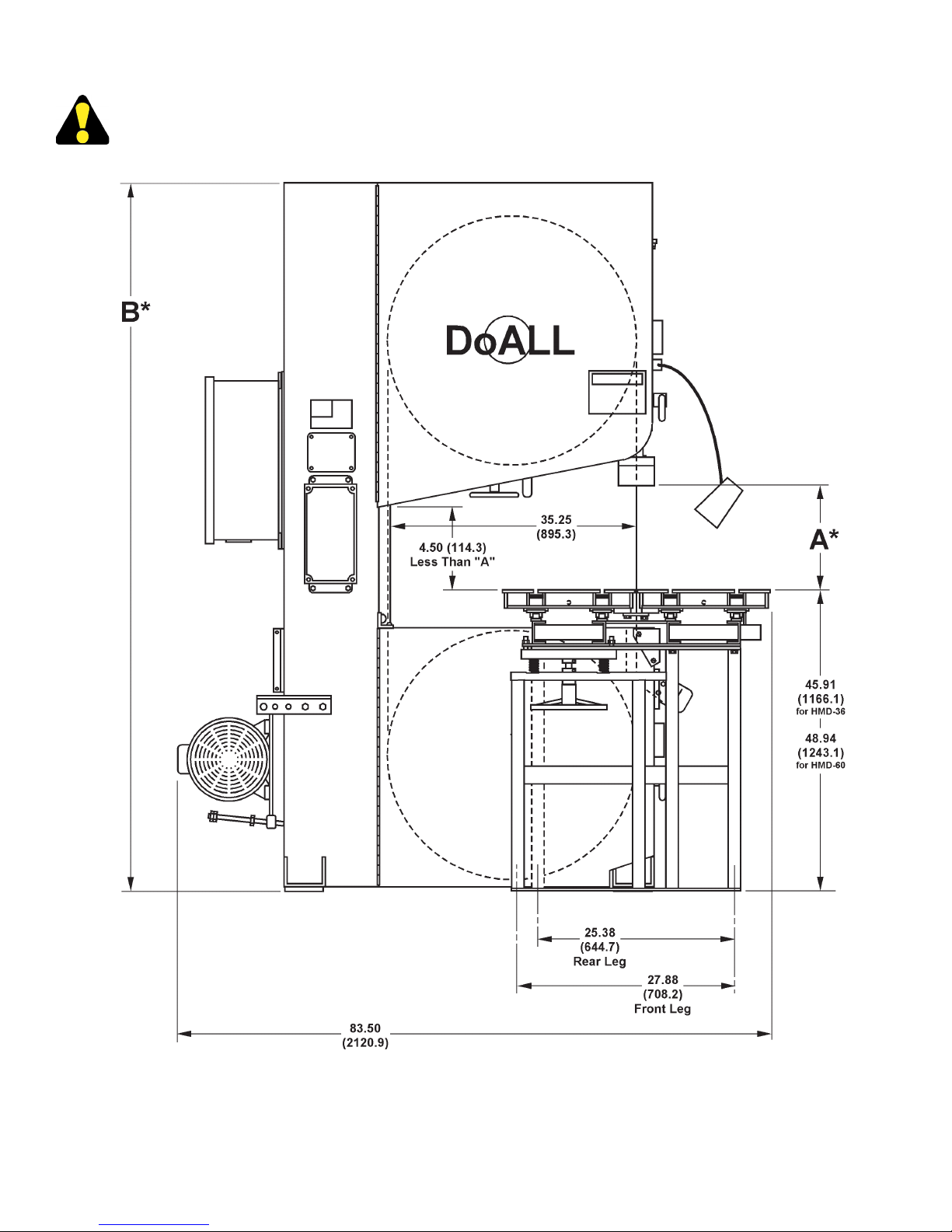
Floor Plan With HMD Hydraulic Table .................... 2
Front View .............................................................. 3
Front View With HMD Hydraulic Table ................... 4
MACHINE FEATURES
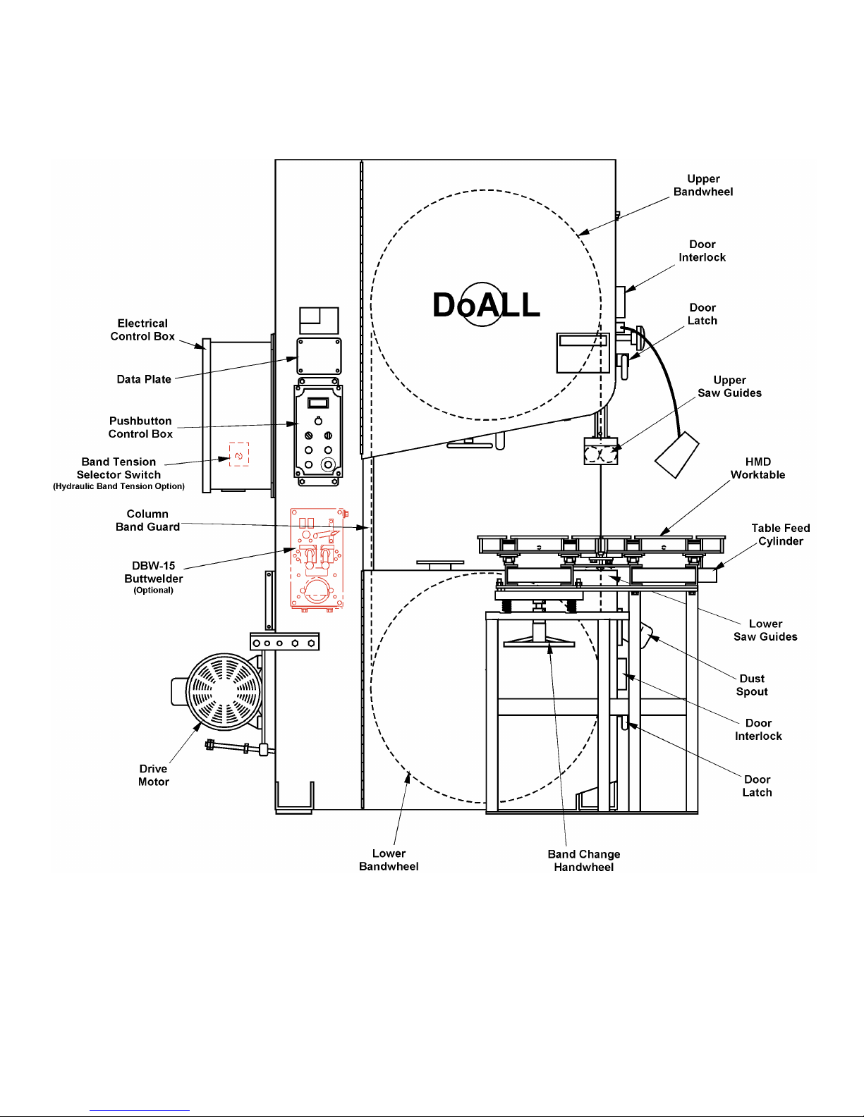
Front View .............................................................. 5
Front View With HMD Hydraulic Table ................... 6
Rear View ............................................................... 7
Raer View With HMD Hydraulic Table .................... 8
INSTALLATION
Location .................................................................. 9
OSHA Notice!! ........................................................ 9
Unpacking ............................................................... 9
Cleaning ................................................................. 9
Lifting ...................................................................... 9
Machine Installation and Alignment ........................ 9
Electrical Installation ............................................... 10
Table Alignment (Standard) .................................... 10
Table Alignment (HMD Table) ................................. 11-12
Preparation for Use ................................................ 12
OPERATION
Safety Precautions ................................................. 13
Friction Sawing ....................................................... 13
Machine Controls .................................................... 13-14
Table Controls ......................................................... 14
Band Speed Control ............................................... 15
Saw Band Tension Handwheel ............................... 15
Saw Band Tracking Lever ....................................... 15
Saw Band Preparation ............................................ 15-17
Post Adjustment ...................................................... 17
Spark Guard ........................................................... 17
Worktable and Adjustments .................................... 17-18
Dust Spout .............................................................. 18
Hydraulic Brake ...................................................... 18
Typical Sawing Procedures .................................... 18-19
LUBRICATION
Lubrication Chart .................................................... 20
Lubrication Diagram ............................................... 21
MAINTENANCE
Changing Belt ......................................................... 22
Electric Motors ........................................................ 22
Head Components .................................................. 22
Hydraulic Brake ...................................................... 22
Hydraulic System .................................................... 22-23
Hydraulic Table (Optional) ...................................... 23
Saw Guides ............................................................ 23
Machine Cleaning ................................................... 23
Bandwheel Tire Replacement (Sheet Metal
Bandwheels) ........................................................ 24-25
Bandwheel Tire Replacement (Cast Aluminum
Bandwheels) ........................................................ 25-26
TROUBLE SHOOTING .................................. 27-29
ACCESSORIES
Disc Cutter .............................................................. 30
Rip Fence ............................................................... 30
Worklamp ............................................................... 30
Magnier ................................................................. 30
Chip Blower ............................................................ 30
DBW-15 Buttwelder ................................................ 31
Workholding Jaw .................................................... 31
Secondary Table ..................................................... 31
Hydraulic Tables ..................................................... 31-32
Glide Table .............................................................. 32
Optional Saw Guides .............................................. 32
Extra Work Height .................................................. 32
Hydraulic Band Tension .......................................... 32
Band Lubricator ...................................................... 32
Dust Collector ......................................................... 32
Safety Equipment ................................................... 33
Material Handling Equipment ................................. 33

1
MACHINE DIMENSIONS
INCHES (± .03)
MILLIMETERS (± 1 mm)
FLOOR PLAN
Table Dimensions
Standard
Table
Glide
Table
Hydraulic
Table
A36.25
(920.8)
32.63
(828.8)
41.00
(1041.4)
B30.50
(774.7)
25.39
(644.9)
32.00
(812.8)
Optional

2
MACHINE DIMENSIONS (Continued....)
INCHES (± .03)
MILLIMETERS (± 1 mm)
FLOOR PLAN With HMD HYDRAULIC TABLE

3
MACHINE DIMENSIONS (Continued....)
INCHES (± .03)
MILLIMETERS (± 1 mm)
FRONT VIEW
Dimensions
A B C
Work
Height
20.00" (508.0) 15.50" (393.7) 103.25" (2622.6)
30.00" (762.0) 25.50" (647.7) 113.25" (2876.6)
36.00" (914.4) 31.50" (800.1) 119.25" (3029.0)
42.00" (1066.8) 37.50" (952.5) 125.25" (3181.4)

4
MACHINE DIMENSIONS (Continued....)
INCHES (± .03)
MILLIMETERS (± 1 mm)
*"A" and "B" Is Dependent On Work Height Ordered.
FRONT VIEW With HMD HYDRAULIC TABLE

5
MACHINE FEATURES
FRONT VIEW

6
MACHINE FEATURES (Continued....)
FRONT VIEW With HMD HYDRAULIC TABLE

7
MACHINE FEATURES (Continued....)
REAR VIEW

8
MACHINE FEATURES (Continued....)
REAR VIEW With HMD HYDRAULIC TABLE

9
INSTALLATION
All the “left”, “right”, “front” and “rear”
designations in this manual are as viewed by
the operator facing the machine’s pushbutton
controls.
LOCATION
1. The oor area required for the standard machine is
approximately 81.50 inches (2070.1 mm) in width
by 36.25 inches (920.8 mm) in length. Machine
height for the standard machine is 103.25 inches
(2622.6 mm). Optional tables may require extra
space. Refer to pages 1 thru 4 for further machine
dimensions.
2. Locate the machine to provide adequate space
for your sawing needs. Be sure also to provide
sufcient clearance for: (a) Loading and unloading
of stock; (b) All door openings; (c) Maintenance and
lubrication procedures; (d) Plus any operation of
any machine options, if applicable.
OSHA NOTICE!!
OSHA Regulation 1910.212 (5B).
Machinesdesignedforaxedlocationshall
be securely anchored to prevent walking or
moving.
UNPACKING
1. In most cases, the machine is fastened to and
shipped on a wooden skid and shipped on its
side.
2. If shipped on its side, tip the machine upright rst
before removing any other shipping materials.
3. Carefully remove all protective covers, strapping,
hold-down brackets, crating, etc. Then: (a) Remove
all bolts which fasten the machine to the shipping
skid; (b) Check for other removable brackets, extra
machine parts or supplies which might have been
placed for shipment; (c) DO NOT remove the motor
blocking until the machine is placed in desired
position; (d) Inspect the machine and all parts for
shipping damage. Claim procedures are listed on
this manual’s inside front cover.
CLEANING
1. If necessary, use solvent to remove any rust-
preventive coating applied to exposed bare metal
surfaces before shipment.
LIFTING
1. A tapped hole is located on top of the machine’s
column. Screw a forged 3/4-10NC eye-bolt into
this hole for lifting purposes. An overhead hoist
is recommended. The weight of the machine is
approximately 3500 pounds (1587.6 kg).
DO NOT lift the machine by the sawing
head.
2. Lifting of the HMD hydraulic table can be done by
a fork lift or overhead hoist. Distribute the weight
evenly when lifting. Approximate weight of the table
is 1500 pounds (680.4 kg).
MACHINE INSTALLATION and ALIGNMENT
Drive Motor Installation (When Machine Was Shipped
On Its Side)
1. Install the two (2) motor supports. The supports
have been correctly aligned and doweled at the
factory. Then: (a) Slip in the motor base weldment
into the supports and install cotter pins; (b) Place
the belts around both motor and spindle pulleys; (c)
Adjust the belt tension screw so very little deection
is noticed; (d) Install the belt guard to the machine
frame.
Drive Assembly.
DO NOT change the location of the motor
or spindle pulley as they have been factory
aligned.

10
ELECTRICAL INSTALLATION
Electrical installation must be made by
authorized electrical maintenance personnel
only!
1. Refer to the machine specications plate on the
machine frame to verify that the electrical supply
circuit will meet the voltage/phase/frequency/
amperage requirements listed. A basic data plate
is reproduced on this manual’s introductory page.
2. Bring the incoming power leads into the
machine’s electrical box enclosure. Refer to the
electrical schematic if necessary when making the
connections.
Controls on the machine may vary. Some may
not have a Band Stop control in which case
the All Stop pushbutton is used.
3. Turn the disconnect switch on the electrical box to
"ON". Then: (a) Intermittenly push the Band Start
and Band Stop pushbuttons; (b) Check to make
sure the saw band is moving in a downward direction
between the saw guides; (c) Reverse the leads if
saw band movement is incorrect.
4. The machine is provided with overload protection,
however, the overload relay may kickout if starting
and stopping occurs numerous times in rapid
succession. If this happens, let the relay cool for
a few minutes, then push the overload reset inside
the control box enclosure before restarting the
machine.
TABLE ALIGNMENT (Standard)
1. Place the machine in desired location. Place a level
on the machine table center. Insert leveling screws
into the mounting pads and make nal shimming
adjustments to level the machine in both directions.
Make sure weight bears evenly on all mounting pads.
DONOTboltthemachinetotheooruntilall
alignment and assembly procedures have been
completed.
MACHINE INSTALLATION and ALIGNMENT
(Continued....)
Squaring Worktable to Post.
2. Place a good quality, 10 inch (254.0 mm) master
square on the worktable against the post’s back side.
Measure clearance between the post and square
near the bottom of the post. Clearance should be
within 0.007-inch ±0.005-inch (0.18 mm ±0.13 mm)
at the bottom of the post for standard machines.
3. Add or remove shims under the base pads until the
correct post to square clearance is obtained.
Themachinemustbeboltedtotheoorfor
worktable loads over 100 pounds (45 kg).
Hydraulic Installation (If Required)
1. Connect the hydraulic hoses from the power unit
to the hydraulic valve manifold on the saw column
or the hydraulic power unit. Hoses are numbered
and tagged for correct installation. Referring to the
hydraulic schematic will be helpful when making the
connections.
2. The power unit must be used to check table travel
with the saw band and raise the post.
3. If necessary, ll the hydraulic reservoir. The standard
reservoir is located on the saw column. Machines
with hydraulic options has a hydraulic power unit
located either under the HMD table or behind the
machine column.
• Standard reservoir capacity is 2.8 gallons (10.6
liters) and ten (10) gallons (37.8 liters) for the typical
hydraulic power unit. Both are lled with automatic
transmission uid.
4. Operate all the controls and check for correct
operation. Let the hydraulic system run for several
minutes to remove entrapped air.

11
TABLE ALIGNMENT (HMD Table)
1. Place the machine in desired location. Place
a level on the machine table base plate. Insert
leveling screws into the mounting pads and make
nal shimming adjustments to level the machine
in both directions. Make sure weight bears evenly
on all mounting pads. DO NOT bolt the machine
to the oor until all alignment and assembly
procedures have been completed.
2. Remove the saw band according to the instructions
in the "Operation" section in this manual. Then raise
the saw guide post to its highest position.
Hydraulic Installation (If Required)
1. Connect the hydraulic hoses from the power unit
to the hydraulic power unit. Hoses are numbered
and tagged for correct installation. Referring to the
hydraulic schematic will be helpful when making the
connections.
2. The power unit must be used to check table travel
with the saw band and raise the post.
3. If necessary, ll the hydraulic reservoir. The reservoir
is located either under the HMD table or behind the
machine column.
• Reservoir capacity is ten (10) gallons (37.8 liters)
for the typical hydraulic power unit and lled with
automatic transmission uid.
4. Operate all the controls and check for correct
operation. Let the hydraulic system run for several
minutes to remove entrapped air.
Table Positioning and Alignment
1. Position the HMD table onto the machine base
making sure the table is setting rmly on the table
base plate of the band saw. Loosely install hex. cap
mounting screws to attach the table to the machine
frame. DO NOT TIGHTEN at this time.
Typical Table Mounting Block.
2. Adjust the table leg leveling screws to roughly level
and square the table to the saw.
3. Turn the disconnect switch to "ON". Then: (a)
Push the Hydraulic Start pushbutton to activate
the hydraulics; (b) Turn the Post selector switch to
"UP" and raise the post to its highest position; (c)
Move the table to the rear postion by turning the
Table selector switch to "REV" or; move the Table
Feed Control to "REVERSE".
4. Reinstall the saw band. To do this you must lower
the table support bar so a gap is created for the saw
band can slip through.
5. Remove the table slot clamp bar at the edge of
the saw band slot. Then turn the Band Change
Handwheel clockwise (located under the forward
section of the table) to lower the table support bar
until the saw band can slip through the opening.
Reinstall the table slot clamp bar and turn the
handwheel back to its preset stop.
6. Reinstall the saw band according to the instructions
in the "Operation" section of this manual.
7. After the saw band is installed and tensioned, position
the table as such that the saw band tracks in the
center of the slot. Adjust the leveling screws in the
legs to stabilize the table.
8. Lower the post to just clear the table. Place a
square of known accurarcy on the table against the
throat side of the post and check the post-to-table
squareness. Post should be square to the table to
0.002 inch per inch (0.05 mm per 25 mm). Adjust
the leveling screws in the legs.
9. Place a good quality ten (10) inch master square
on the table against the backside of the saw guide
post. Measure the clearance between the square
and the post near the bottom of the post. Clearance
should be within 0.007 ± 0.005 inch (0.18 ±0.13
mm). Adjust the set screws in the table mounting
pad.
Squaring Post to the Table.

12
10. Add or remove shims under the base pads until the
correct post to square clearance is obtained.
11. With an indicator mounted to the saw guide post,
check table travel by positioning the indicator to
read off of the T-slot in the table. Traverse the table
through its full travel and adjust to achieve from 0
to .015 inch per 30 inches (0 to 0.38 mm per 762.0
mm) of travel.
12. When table and machine are in correct alignment
and level, tighten the mounting screws and then
tighten the jam nuts on the leveling bolts.
PREPARATION FOR USE
1. Remove the pipe plug from on top of the upper
spindle for venting purposes, not the two (2) from
the side and bottom of the spindle.
2. Be sure the hydraulic reservoir is full. Refer to the
Lubrication Chart for recommended uid.
• If necessary, replace the plug on top of the reservoir
with the breather from the box of extra parts.
3. Shop air is required to operate the optional chip
blower or band lubricator. Incoming air supply should
be between 80 and 90 psi (5.6 and 6.3 kg/cm²).
DONOTexceed90psi(6.3kg/cm²).
4. Check the optional band mist lubricator unit for the
proper reservoir level. Refer to the manufacturer
supplied literature for reservoir capacity and
recommended procedures.
5. Make sure all other points listed by the Lubrication
Chart have been properly checked and/or
serviced.
TABLE ALIGNMENT (HMD Table) (Continued....)

13
Thicker the workpiece, the faster the band
speed required and heavier the feed force.
Forexample,bandspeedshouldbeatleast
6000fpm(1828.8m/min.)for1/4inch(6.4mm)
thickcarbonsteel;12,500fpm(3810.0m/min.)
for one (1) inch (25.4 mm) thick material.
MACHINE CONTROLS
Depending on options supplied (if any), some
controls may not apply to your machine
application.
1. Band Speed Display. This digital readout displays
the band speed in feet per mimute.
2. Band Speed Control. This control allows the
operator to change the band speed. Turning the
knob clockwise to “increase” the band speed;
counterclockwise to “decrease” it.
OPERATION
SAFETY PRECAUTIONS
Warning Label - READ and UNDERSTAND.
FRICTION SAWING
1. The design of this machine makes it ideal for
friction sawing. In friction sawing, momentary
contact between the material being cut and the
fast moving saw band produces enough friction to
heat the material to its softening point. As soon
as it becomes soft, it is cut away by the saw band
teeth. This method cuts many times faster than
conventional methods and cuts many materials that
can not be machined any other way.
2. Keep these important points in mind while friction
sawing:
Roller saw guides are required for friction
sawing.
Attach the spark shield to the post is necessary
for friction sawing. Coolant is not used.

14
Typical Machine Controls.
3. Hydraulic Start (Optional). Pushing this illuminated
green button starts the hydraulic pump motor for the
optional band tension and/or hydraulic table.
4. Hydraulic Stop (Optional). Pushing this red button
stops the hydraulic pump motor for the optional
band tension and/or hydraulic table.
5. Post. When the operator turns and holds this
selector switch to the “UP” or “DOWN” position, it
allows the movement of the post. Releasing the
selector switch springs to the “HOLD” position and
stops the post in position.
6. Band Start. Pushing this illuminated green button
starts the band drive.
7. Band Stop. Pushing this red button stops the band
drive.
8. All Stop (Emergency Stop). Pushing this red
mushroom head button stops the band drive motor.
To resume operation, the All Stop button must be
reset by rotating the head of the button clockwise
until the head pops out.
9. The optional Worklight has its own “ON-OFF”
switch on the lamp.
10. Controls for the optional DBW-15 Buttwelder are
described in a seperate instruction manual.
TABLE CONTROLS (If Supplied)
1. Feed Force. This controls the force against the
saw band. Force is indicated on a graduated dial
around the control.
Table Controls.
2. Table Feed. This control with "REVERSE", "STOP",
"FEED", and "FORWARD" settings controls table
movement in either direction.
• The "REVERSE" setting moves the table away from
the saw band at a rapid traverse speed.
• The "STOP" setting stops all table movement.
• The "FEED" setting is for sawing and used in
conjunction with the Table Speed Control.
• The "FORWARD" setting moves the table toward
the saw band at a rapid traverse speed.
The "FORWARD" setting is NOT used for
cutting stock.
3. Table Speed Control. When the Table Feed
Control is at the "FEED" setting, the table speed can
be regulated by turning the center knob clockwise
to increase table speed, counterclockwise to
decrease it. Forward speed range is approximately 0
to 8 fpm (0 to 2.4 m/min.); feed rate is approximately
0 to 18 ipm (457.2 mm/min.).
4. Table. Some machines may have a selector switch
with "REV", "HOLD" and "FWD" settings to control
table movement.
• (a) Turn the selector to "REV" (reverse) moves the
table back and away from the saw band; (b) Turn
the selector to "FWD" (forward) moves the table
towards the teeth of the saw band; (c) Turning the
selector to "HOLD" stop table movement in either
direction.
MACHINE CONTROLS (Continued....)

15
4. The back edge of the saw band should just touch
the back-up ange of the saw guide rollers, or the
back-up bearings on insert type saw guides.
5. Close both bandwheel doors.
SAW BAND PREPARATION
Information about any DoALL saw bands
and their applications can be obtained from
a DoALL sales representative.
Saw Band Selection
1. The standard machine is equipped with a friction
saw band that is 234 inches (5343.6 mm) long. It
will accept saw band widths from 1/16 to one (1)
inch (1.6 to 25.4 mm). Extra work height machines
requires longer saw bands.
2. Optional saw guides that can be used:
• One (1) set of double row, heavy duty ball bearing
saw guide with rollers for one (1) inch (25.4 mm)
wide saw band. Rollers for saw bands 1/4 to 3/4
inch (6.3 to 19.0 mm) are also available.
• One (1) set of insert-type precision saw guide blocks
with inserts for saw bands from 1/16 to 1/4 inch (1.6
to 6.3 mm) wide.
Roller-Type Saw Guide Adjustment-Type III
These instructions apply to both the upper
and lower roller-type saw guide blocks.
1. Select the saw guide blocks and rollers marked
for the width of the saw band to be used. Then:
(a) Place one (1) side roller and one (1) back-up
roller in the upper saw guide block; (b) Switch the
rollers around for the lower saw guide block; (c)
Install the special adaptors onto the post and table
cradle; (d) Then install the saw guide blocks on the
adaptors.
2. After the saw guides are in place, the saw band
should be in place and tensioned. See later in
this section on installation and tensioning the saw
band.
3. Loosen the clamp screws and bring the rollers up to
the saw band, then tighten the screws. The rollers
should be free enough to turn without moving the
saw band.
BAND SPEED CONTROL
1. Speed range can be innitely varied with the Band
Speed control. The speed is shown on an display
located above the control.
2. Band speed is changed by turning the Band Speed
control to the desired speed as indicated on the
band speed display.
4. During machine operation, keep the following band
speed precautions in mind:
Adjust the band speed only while the machine
is running.
Always turn the band speed control to “slow”
before stopping the machine.
Always allow the saw band to stop completely
before opening any bandwheel doors.
SAW BAND TENSION HANDWHEEL
1. Saw band tension is adjusted by turning the
handwheel located below the machine’s sawing
head.
2. A scale showing the recommended tension for
various saw band widths is located to the right of the
tension adjustment handwheel near the post. Scale
numbers represent the recommended tensions for
common saw band gages and pitches.
Optional hydraulic band tension is factory set.
DO NOT adjust the handwheel if supplied!
SAW BAND TRACKING LEVER
1. The upper bandwheel can be tilted a maximum of
ve (5) inches (127.0 mm) forward and backward to
help obtain correct saw band tracking. This is done
by the use of the bandwheel tilting lever located
behind the band tension handwheel. A saw band is
tracking properly when the saw band center follows
the center of both crowned bandwheel tires.
2. The following tracking procedures are to be
performed with the band drive motor "OFF": (a)
Open both bandwheel doors; (b) Manually turn
the bandwheels to observe how the saw band is
tracking.
3. Move the bandwheel tilting lever to adjust the
position of the bandwheel; to the left to track the
saw band “IN”; to the right to track the saw band
“OUT”.

16
Insert-Type Saw Guide Adjustment
These instructions apply to both the upper
and lower insert-type saw guide blocks.
1. Select the saw guide blocks and inserts marked
for the width of the saw band to be used. Then:
(a) Place the right insert in the right milled slot; (b)
Tighten the insert screw slightly so that the insert
will slide in the slot, yet still hold its correct position
when released.
Positioning the Right Insert.
2. Select the insert gage which matches the size of the
saw band being used. Then: (a) Place the insert
gage in the left slot; (b) Adjust the right insert to t
exactly into the notched end of the gage; (c) Tighten
the right insert screw.
3. Place the left insert in its slot and tighten the insert
lightly. Then: (a) Place the gage edgewise between
both inserts; (b) Lower the left insert until it rests
against the gage; (c) Tighten the left insert screw.
Positioning the Left Insert.
Saw Band Removal
Alwaysuseextremecarewhenhandlingsaw
bands. Wear gloves.
1. Turn the band tension handwheel to release saw
band tension. Then: (a) Open both bandwheel
doors; (b) Open the post and the column saw
band guards; (c) Loosen the knobs holding the
worktable’s sawing slot ller plate and remove it.
2. Carefully slip the worn or broken saw band from
between the saw guides rollers or inserts and table
slot and remove it from around both bandwheels.
Saw Band Installation
Alwaysuseextremecarewhenhandlingsaw
bands. Wear gloves.
1. Remove the old saw band according to the
directions above. Then: (a) Place the new saw
band carefully (teeth facing down and to the front)
through the table slot, around the bandwheels and
between the upper and lower saw guide rollers or
inserts; (b) The center of the saw band should track
along the center of the bandwheel tires.
2. Remove the new saw band’s protective Saw Cap.
Then: (a) Apply the band tension recommended
by the dial located on the front of the column; (b)
Close the post and the column saw band guards;
(c) Replace and secure the worktable’s sawing slot
ller plate.
Saw Band Tension Adjustment
1. Saw band tension is adjusted by turning the
handwheel located below the machine’s sawing
head.
Optional hydraulic band tension is factory set.
DO NOT adjust the handwheel if supplied!
2. A scale showing the recommended tension for
various saw band widths is located to the right of the
tension adjustment handwheel near the post. Scale
numbers represent the recommended tensions for
common saw band gages and pitches.
SAW BAND PREPARATION (Continued....)
Table of contents
Other DoAll Saw manuals

DoAll
DoAll C-260 NC Parts list manual

DoAll
DoAll c-530 nc User manual

DoAll
DoAll DS-320SA User manual

DoAll
DoAll C-4033NC User manual

DoAll
DoAll C-260 NC Parts list manual

DoAll
DoAll 500SNC User manual

DoAll
DoAll TF-2525 User manual

DoAll
DoAll c-530 nc Parts list manual

DoAll
DoAll C-916S User manual

DoAll
DoAll C-520NC User manual