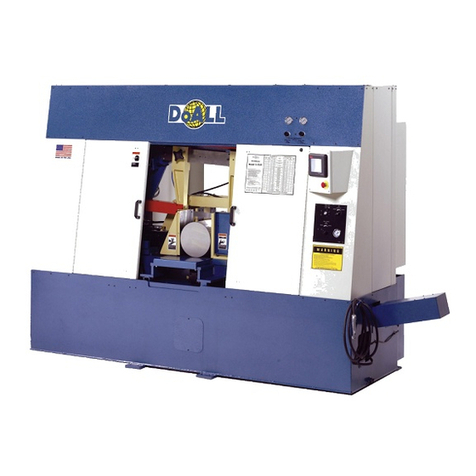
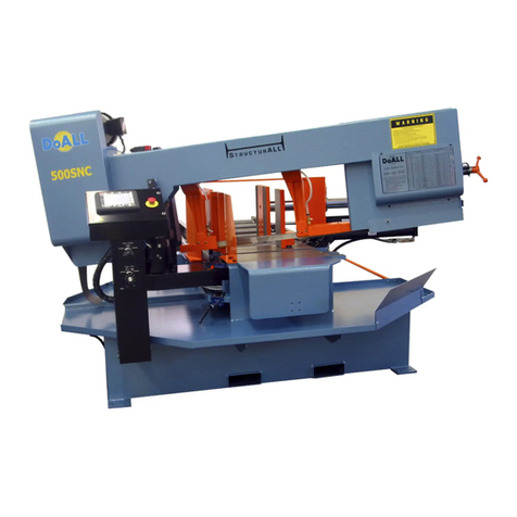
DoAll DS-320SA User manual

INSTRUCTION MANUAL
BAND SAW MACHINES
TYPE DS-320SA
Version
II.generation
–
version 2
DoALL Sawing Products
800-321-9913
5505 West 123rd Street
Minneapolis, MN 55378
www.doallsaws.com

DS-320SA
Instruction Manual - 2 - www.doallsaws.com
1. CONTENT
1. CONTENT ...................................................................................................................................................... 2
2. INTRODUCTION ............................................................................................................................................ 4
2. DESCRIPTION OF THE MACHINE ............................................................................................................... 4
2.1 OPERATING CYCLE ............................................................................................................................... 4
2.2 CONTROL SYSTEM ................................................................................................................................ 4
2.3 CONSTRUCTION .................................................................................................................................... 5
2.4 STANDARD EQUIPMENT ....................................................................................................................... 5
2.5 BASIC EQUIPMENT OF MACHINE ........................................................................................................ 5
2.5.1 SET OF TOOLS FOR COMMON SERVICE ................................................................................ 6
2.6 PURPOSE OF THE MACHINE ................................................................................................................ 7
3. TECHNICAL DATA ........................................................................................................................................ 8
3.1 CUTTING PARAMETERS ....................................................................................................................... 8
3.2 DIMENSIONS FOR TRANSPORT .......................................................................................................... 8
3.3 INFORMATION ON DRIVE ...................................................................................................................... 9
3.4 THE AMOUNT OF SERVICE/OPERATING FLUIDS .............................................................................. 9
3.5 EMISSIONS – MACHINE NOISE LEVEL ................................................................................................ 9
3.6 PRODUCTION LABEL ........................................................................................................................... 10
4. MAIN PARTS AND FUNCTIONS ................................................................................................................ 11
4.1 VICE ....................................................................................................................................................... 12
4.2 ARM ....................................................................................................................................................... 13
4.3 HYDRAULIC UNIT ................................................................................................................................. 14
5. SAFETY RULES .......................................................................................................................................... 15
5.1 SAFETY DURING OPERATION ............................................................................................................ 15
5.2 LIST OF POSSIBLE DANGERS WHEN WORKING WITH MACHINE ................................................. 16
5.2.1 MECHANICAL RISK ................................................................................................................... 16
5.2.2 ELECTRICAL RISKS .................................................................................................................. 16
5.3 FIRE PROTECTION .............................................................................................................................. 16
5.4 ELECTRICAL EQUIPMENT................................................................................................................... 17
5.5 IT IS PROHIBITED TO ........................................................................................................................... 17
5.6 SAFETY REGULATIONS ...................................................................................................................... 18
5.6.1 SAFETY COMPONENTS ........................................................................................................... 19
5.7 DESCRIPTION OF LABELS .................................................................................................................. 20
6. INSTRUCTIONS FOR TRANSPORT .......................................................................................................... 22
7. DIRECTIVES FOR STORAGE .................................................................................................................... 22
8. MACHINE INSTALLATION ......................................................................................................................... 23
8.1 INSPECT MACHINE FOR SHIPPING DAMAGES ................................................................................ 23
8.2 SHIPPING BRACKETS .......................................................................................................................... 23
8.3 INSTALLING THE MACHINE ................................................................................................................ 23
8.3.1 FOUNDATION REQUIREMENTS .............................................................................................. 23
8.3.2 ACHORING INSTRUCTIONS: ................................................................................................... 24
8.4 INSTALLING THE ROLLER TABLE ...................................................................................................... 25
8.5 HOW TO ANCHOR MACHINE TO THE FLOOR .................................................................................. 26
8.6 CONNECTING TO THE ELECTRICAL NET ......................................................................................... 26
9. DESCRIPTION OF MAIN PANEL ............................................................................................................... 27
9.1 KEYPAD ................................................................................................................................................. 28
9.2 HMI PANEL ............................................................................................................................................ 29
9.2.1 STARTING SCREEN .................................................................................................................. 29
9.2.2 MENU ......................................................................................................................................... 30
9.2.3 NUMERIC KEYPAD ................................................................................................................... 30
9.3 /1.PAR/ USER PARAMETERS .............................................................................................................. 31
9.4 /2.MAN/ MANUAL SAW CONTROL ...................................................................................................... 33
9.5 PREPARATIONS BEFORE CUTTING .................................................................................................. 34
9.6 INITIATION OF THE MACHINE INTO THE STAND-BY MODE ........................................................... 35
9.7 ANGLE SETTING .................................................................................................................................. 36
9.7.1 CUTTING OF THE RIGHT ANGLE CUTS ................................................................................. 36
9.7.2 CUTTING OF THE LEFT ANGLE CUTS .................................................................................... 36
9.7.3 DIGITAL POINTER OF THE ANGLE (ACCESSORIES) ........................................................... 37
9.8 ADJUSTMENT OF THE WORKING POSITION .................................................................................... 38
9.8.1 ADJUSTMENT OF THE UPPER WORKING POSITION ........................................................... 38
DS-320SA
Instruction Manual - 3 - www.doallsaws.com
9.8.2 ADJUSTMENT OF THE DOWN WORKING POSITION ............................................................ 38

9.9 VICE ADJUSTMENT - HOW TO CLAMP THE MATERIAL WELL ....................................................... 39
9.10 GUIDE POSITION ADJUSTMENT ...................................................................................................... 39
9.11 LUBRICATION OF THE SAW - BAND ................................................................................................ 40
9.12 HOW TO SET THE ADJUSTABLE END STOP ................................................................................. 40
9.13 HANDLING THE MATERIAL ............................................................................................................... 40
10. CUTTING - SEMIAUTOMATIC CYCLE ..................................................................................................... 41
10.1 BASIC CONDITIONS FOR CUTTING ................................................................................................. 41
10.2 HYDRAULIC UNIT – TURNING ON .................................................................................................... 41
10.3 CUTTING ............................................................................................................................................. 41
10.4 ERROR MESSAGES ........................................................................................................................... 41
10.5 15 RULES FOR OPTIMAL CUT .......................................................................................................... 44
11. INFORMATION ABOUT THE BLADE ....................................................................................................... 45
11.1 TENSIONING OF THE SAW-BAND .................................................................................................... 45
11.2 BAND REPLACEMENT ....................................................................................................................... 46
11.3 GUIDES OF THE BLADE .................................................................................................................... 47
11.4 HOW TO REPLACE THE CLEANING BRUSH ................................................................................... 48
11.4.1 HOW TO CHANGE THE BRUSH .......................................................................................... 48
12. HOW TO CHOOSE THE RIGHT SAW-BLADE......................................................................................... 49
12.1 SAW-BLADE TEETH ........................................................................................................................... 49
12.2 HOW TO CHOOSE THE RIGHT TEETH FOR CUTTING ................................................................... 50
12.3 RUN IN OF SAW-BLADE - WHEN HAVING A NEW SAW-BLADE .................................................... 50
12.4 HOW TO CLAMP MATERIAL .............................................................................................................. 51
12.5 SPEED OF ARM MOVEMENT WHEN CUTTING ............................................................................... 51
12.5.1 EXTRA ACCESSORIES ........................................................................................................ 52
12.6 MINI-LUBE ........................................................................................................................................... 54
5.5.1 SETTING AND ADJUSTMENT ...................................................................................................... 54
12.6.1 CONTROL .............................................................................................................................. 54
12.7 HYDRAULICAL UPPER VICE .............................................................................................................. 55
12.7.1 UPPER THRUST SETTING ................................................................................................... 55
12.7.2 CONTROLLING OF UPPER THRUST ................................................................................... 56
12.7.3 ASSEMBLY / DISMANTLE OF UPPER THRUST .................................................................. 56
12.8 LIGHT ................................................................................................................................................... 56
12.9 ROLLER TABLE .................................................................................................................................. 57
13. MAINTENANCE ......................................................................................................................................... 61
13.1 LUBRICATION CHECKING ................................................................................................................. 62
13.2 RECOMMENDED FILLINGS- INTERVALS FOR CHANGING FILLINGS .......................................... 63
13.3 CHANGE OF HYDRAULIC OIL ........................................................................................................... 63
13.4 FILLING THE TANK WITH OIL ............................................................................................................ 64
13.5 FILLING AND CHANGING PUMP COOLANT..................................................................................... 64
13.5.1 STIRRING THE COOLANT .................................................................................................... 65
13.5.2 PROPORTION OF OIL AND WATER MIXTURE .................................................................. 65
13.5.3 LIFETIME OF THE COOLANT ............................................................................................... 65
13.6 CHANGE OF GEAR OIL ...................................................................................................................... 65
13.6.1 TECHNICAL MAINTENANCE OF GEARBOXES .................................................................. 65
14. SERVICE INSTRUCTIONS ........................................................................................................................ 66
14.1 ADJUSTMENT OF BAND GUIDES ..................................................................................................... 66
14.2 ADJUSTMENT OF CLEARANCE BETWEEN THE SAW-BAND AND CARBIDE PADS.................... 67
14.3 ADJUSTMENT OF THE TENSIONING PULLEY ................................................................................ 68
14.4 ADJUSTING THE HYDRAULIC PUMP PRESSURES: ....................................................................... 69
14.5 SETTING PRESSURES ...................................................................................................................... 69
14.6 REPLACING THE COUPLING BETWEEN THE ELECTRIC MOTOR AND HYDRAULIC PUMP ...... 70
14.7 HOW TO SOLVE PROBLEMS-MACHINE .......................................................................................... 72
15. CLOSING ................................................................................................................................................... 73

DS-320SA
Instruction Manual - 4 - www.doallsaws.com
2. INTRODUCTION
The Instruction Manual was written to comply with the rules and regulations established by the Federal
Trade Commission (FTC) for equipment being sold to customers. The Instruction Manual contains
installation, operation and safety instructions. The operator should read the manual and keep it handy for
future reference. It is very important for operators of the machine to read the Instruction Manual carefully.
Warning: Producer and supplier of a machine has the right to make technical changes on its products
and to make changes in manual instructions without previous warning.
2. DESCRIPTION OF THE MACHINE
Semiautomatic machine with hydraulic manipulation.
The machine is designed for cutting of material in vertical and angle cuts, angle cuts are possible to set
fluently from 60° right to 45° left.
It is suitable for piece production and small series production. The machine is so durable that it can be used
to cut a wide range of profiles and materials, including piece production and small series production.
The machine is designed to saw steel materials, but also non-ferrous and light metals. However, we
recommend consulting the manufacturer about this option.
No other materials may be sawn without approval from the manufacturer.
2.1 OPERATING CYCLE
After manual adjustment of the jaws the operator starts the cycle with a switch on the control panel. The
hydraulic cylinder of the vice grips the material and the saw starts working. The cutting speed of the arm is
controlled by a throttle valve. Arm and vice movements after cut following set users parameters. The vice
opens and the operator can handle the material.
2.2 CONTROL SYSTEM
The machine features a Mitsubishi PLC control system, which features an automatic feed control
BRP.
Control panel MITSUBISHI as standard equipment. It uses touch display and PLC, which enable
semi-automatic cutting (basic setting encluded) as well as communication with operator.
The control system displays information about the cutting process:
o Cutting cycle indication,
o indication BRP,
o indication – blade tightening,
o time of the cut,
o loading of blade in amperes,
o speed of the blade,
o cutting times measuring,
o list of error messages.
User´s setting:
o autostop of hydraulic unit
o mode of arm moving after end of the cut
o mode time lag of shift speed
o mode blade moving
o mode jaw moving after cutting cycle finish
o diagnostic of inputs and outputs
STOP function – cutting : it enables to stop cutting by pressing STOP button at any time. The Frame
goes up with the running blade without opening the vice.
Regulation of shaft speed (moving to cut) is manual and uses throttle valve placed beside control
panel. Automatic (safety) regulation of shift speed BRP. Principle: Machine will stop after exceeding
set loading (defined in ampers).
Extenally situated controlling panel - its position does not depend on the position of turntable position
during angular cuts. There is equipped with a safety button, which stops the saw. There is also a
feed regulator and buttons which controls the various available movements.

DS-320SA
Instruction Manual - 5 - www.doallsaws.com
2.3 CONSTRUCTION
The machine is designed in that way, so that it corresponds to extreme exertions in productive
conditions.
The arm on the machine is designed to make precision cuts. The arm is sloped twenty-five degrees
to increase blade life.
The arm is rotated by a shaft(joint) which is support by adjustableconical bearings
Cast iron pulleys are used with the drive motor.
Upper working arm position controled by automatic stopper (DPP)
The down working position of the arm controlled by the miscroswitch. In the end position
microswitch is on, arm goes to selected upper position.
The vice is made from cast iron. Jaws ensure safe clamping of the material.
The hydraulically operating vice with short travel is placed in an adjustable dovetail groove.
Moving jaw of the vice is manual with a wheel and trapeze thread. Speedy jaw adjustment is
achieved by means of a lever, spring and trapeze half-nut.
Basic part of the vice moves according to the direction of the angle cut setting, fixation is made by
the handle.
Turn table is cust iron. A turntable gives a big place for supportion of material and its perfect
clamping.
Manuall turning of the table for angle cuts, angle fixation using handle. The turning table has
autoarresting every 15 grades (the groove with the spring).
General angles are adjusted by the nonius. It is possible to equip the machine by reading of angle by
2.4 STANDARD EQUIPMENT
The blade leading in guides with hardmetal plates and leading bearings and along cast iron pulleys.
There is a guide situated on the firm beam on the drive side. On the tightening side there is the guide
situated on the moving beam.
The guide beams of moving band guide is adjustable. Manual adjustment and fixing of the guide
beams.
Guide holder moves in adjustable dovetail groove.
The saw-band is equipped with a guard, which protects the operator from millings and cutting fluid.
Mechanic tightening of the blade.
Indication the correct tension of the saw blade.
A passive driven cleaning brush for perfect cleaning and function of blade.
The machine is powered by a maintenance-free worm gear box. The 3-phase drive motor is
equipped with a frequency converter that regulates blade speed. The electric motor has thermo-
protection.
The cooling system distributes coolant to the band guides.
Massive base with a tank for chips. Base is designed for manipulation with machine by pallet truck
and also by any fork lift truck.
Indication of blade tightening and opening of the cover.
Controlling 24 V.
The hydraulic system controls all machine functions, including raising and lowering the arm, and
opening and closing the vice.
2.5 BASIC EQUIPMENT OF MACHINE
Band saw blade.
Set of spanners for common service.
Manual instructions in eletronic form (CD).

DS-320SA
Instruction Manual - 6 - www.doallsaws.com
2.5.1 SET OF TOOLS FOR COMMON SERVICE
Item Descritpion
1 Allen wrenches
2 Allen wrench for blade tightenns
3 Wrenchs
pic: 2-1

DS-320SA
Instruction Manual - 7 - www.doallsaws.com
2.6 PURPOSE OF THE MACHINE
The DS-320SA sawing machine is designed:
to cut bars and shaped materials (pipes). The size of bars is defined in a table, chapter 4. Saw is
constructed for cutting of bars of maximal diameter (11,8x12,6in) in length of 236in. At longer bars
the maximal diameter decreases proportionally.
to saw steel materials, but also non-ferrous and light metals. However, we recommend consulting
the manufacturer about this option. No other materials may be sawn without approval from the
manufacturer.
for operation in a standard environment.
The machine is designed and produced to cut bar materials in agreement with the instructions described in
this manual. No other use is permitted.
Sawing is not permitted if the material is not properly gripped in the vice.
The machine is designed to saw steel materials, but also non-ferrous and light metals. However, we
recommend consulting the manufacturer about this option.
No other materials may be sawn without approval from the manufacturer.
To achieve correct operation of the machine and the safety of operators, the structural properties and size of
the saw-band may not be altered under any circumstances and all instructions printed in this manual must be
observed.
The electrical installation should be connected to 3/PE AC 230V 60Hz, TN-C (or 2 AC 24V 60Hz, PELV)
power network, see technical data in the electronic documentation.
The electrical installation of the machine should be used in an environment determined by the valid
regulations and technical standards with the following ambient effects:
AA5 (ambient temperature 40 to 105°F), AB5 (relative humidity up to 95%), AC1, AD1 (negligible presence
of water), AE1, AF1, AG2, AH2, AK1, AL1, AM
negligable effects: AN1, AP1, AQ1, AR1, AS1, BA4 (only qualified persons may operate the machine), BC3,
BD1, BE1, CA1,CB1
The saw machine does not produce excessive high-frequency electromagnetic disturbances. The machine is
expected to operate in an electromagnetic environment as defined in the valid regulations and technical
standards.
Observing the instructions and processes for installation, operation, maintenance and cleaning stated in the
following chapters of this manual, are further conditions for the use of the sawing machine.
NOTICE:
The manufacturer (supplier) bears no responsibility for any damage incurred by using the machine
for different purposes or in different circumstances. All the responsibility falls on the User.
The operator is only allowed to perform the operations described in the manual. Any interference
with the machine not covered in this manual belongs to an authorized company.
Before putting the machine into operation or when teaching a new operator, we recommend studying
the manual properly. Only in this manner will you be able to fully utilise the outstanding properties of
the sawing machine.
We recommend observing the data in the tables for choosing saw-bands. Consult all queries with our
technicians.
In order to achieve the best quality of our services, we only accept written orders (fax, e-mail, surface
mail). When ordering maintenance service, always give the name and model of the sawing machine,
year of production, serial number, name and code of the spare part. Describe the malfunction as
clearly as possible.
band saw machine DS-320SA it is a product that answers demands of technical directives.

DS-320SA
Instruction Manual - 8 - www.doallsaws.com
3. TECHNICAL DATA
To achieve the right function of the machine and the safety of the operator following data can not be
changed in any case:
Protection by cover IP44
performance parameters
drive of the blade Hp 3,5
drive of the hydraulic agregate Hp 0,74
pump of the cooling emulsion Hp 0,17
cooling Hp 0,04
distributor Hp 0,34
total input Hp 6,84
cutting speed fpm 115 - 230
diameter of the blade in 238-1/2
electric connection
3x230V, 60 Hz, TN-C
tab: 3-1
3.1 CUTTING PARAMETERS
cutting parameters
D [in] 11,8 11,8 7,9 10,6 X X
D [in] 7,08* 4,3* 3,2* 4,3* X X
axb [in] 12,6x11,8 11,4x11,8 7,5x7,5 10,6x7,9 X 12,6x6,3
tab: 3-2
*recommended values
the shortest cutting in 0,11
the smallest divisible diameter in 0,2
the shortest rest during one cut in 1,2
tab: 3-3
feed of the Frame to the cut hydraulically
feed of the material manually
clamping of material hydraulically
bend tension manually
cleaning of the blade cleaning brush driven by a pulley
cooling Cooling system for emulsion with liguid distribution to blade guides.
tab: 3-4
3.2 DIMENSIONS FOR TRANSPORT
Parameters
length width Height max height min
height of the table weight
[L] [B] [Hmax] [Hmin] [V] (lb)
80,7 46 80,3 56 31,5 1430
tab: 3-5
* high measurements do not count with the interlay materials that are neccesary for transport.

DS-320SA
Instruction Manual - 9 - www.doallsaws.com
3.3 INFORMATION ON DRIVE
type
rated
output
Pn [hp]
rated
voltage
Un [V]
rated
current
In [A]
Turns
[*min-1]
performance
[l/min]
M1
-
blade
Indukta –
3SIEK90L4A 3,5 230 9,6 1745 -
M1
-
gearbox
Varvel: SRT08528G635, i=28
M2
–
coolant pump
4COA2
-
14 H
P1
+S
-
UL 0,17 230 0,5 - -
M3
-
hydraulic
MAAL71-14F85-4A 0,75 230 2,6 1680 -
tab: 3-6
3.4 THE AMOUNT OF SERVICE/OPERATING FLUIDS
Hydraulic oil
10 l
(10,56qt)
*The amount of hydraulic oil is only for your orientation – the minimum level of oil is determined by the
transparent oil level indicator.
Emulsion oil
12 l
(12,68qt)
*The amount of emulsion oil is only for your orientation. To check the sufficient amount of the coolant – it is
the task of operators of the majority of machines. The level of coolant is from 30 to 60 mm below the level
of the flange of coolant pump.
gear oil
0,6 l
(0,63qt)
There is a longlife syntetic oil filled in the gearboxes: it is not necessary to make any service or filling the oil
during average 15.000 hours of lifetime.
Oil for
MINI
-
LUBE
0,5 l
(0,53qt)
tab: 3-7
3.5 EMISSIONS – MACHINE NOISE LEVEL
In regard to emissions, the machine operators are in no danger of taking in harmful gaseous products during
the operation of the machine.
The machine noise level specifies a method for measuring the emission sound pressure levels of machinery
and equipment at a work station and at other specified positions nearby in a semi-reverberant field. Noise is
measured in units of sound pressure called decibels (dB).
The noise level at a workplace of a machine (the emission sound pressure level) has to be mentioned and
specified in the user manual if it exceeds 70 dB(A).
Table 1. Emissions – Machine Noise Level
Source Definition Noise Level
ISO 11202: 1995 The declared emmisions level of the working machine, anytime the
machine is running/idling.
LpAeg,T =
65+4 [ dB ]
ISO 11202: 1995 The declared emmisions level of the working machine when it is
cutting a low alloy steel.
LpAeg,T =
65+4 [ dB ]

DS-320SA
Instruction Manual - 10 - www.doallsaws.com
3.6 PRODUCTION LABEL
Every machine is equipped with an aluminium tag that contains main technical information answering to the
working and constructional specifications. This tag cannot be removed and must be clean and legible. All
data on this tag must be specified in case of order of spare parts or service.
For your information and future reference, pertinent data concerning your machine should be written in the
spaces provided above. This information is printed on a label attached to your machine. Be sure to provide
machine model and serial numbers with any correspondence or parts orders.
Specifications contained herein were in effect at the time this manual was approved for printing. The DoALL
Company, whose policy is one of continuous improvement, reserves the right, however, to change
specifications or design at any time without notice and without incurring obligations.
PLEASE READ THIS MANUAL CAREFULY BEFORE OPERATING THE MACHINE!
For Sales, Parts and Service, call 1-888-362-5572
For general information, visit our web site at: www.doallsawing.com

DS-320SA
Instruction Manual - 11 - www.doallsaws.com
4. MAIN PARTS AND FUNCTIONS
1. Base of machine
2. Wire installation
3. Control panel
4. Hydraulically operating vice for clamping of material. The adjustment is manual with a wheel and trapeze
thread.
5. Screw for manually tightening of the band.
6. Arm of machine
7. Drive of - worm gear box with and three phase electric motor
8. Automatic stopper at upper working arm position (T-bar)
9. Hydraulic cylinder of arm movement
10. Cam for adjustment of bottom working arm position
11. Measuring end stop
12. Metalic gutter, vessel for chips
13. Turn table of the machine. It carries the arm and enables its turning.
14. Anchoring holes.
15. Hydraulic centrale
16. Main power supply - means of a flexible lead with one end firmly attached to the main connectors of the
machine and the loose end for socket connection (i.e. three-phase, five-pin plug) or for fixed connection
to the object’s electrical power network. (The plug is not supplied).
17. Coolant pump - used to cool the saw blade when cutting. Coolant flows through the blade guides. Pump
operation is controlled through logic machines - cooling blade only machine cycle.
18. Transportation holes for low-lift or high-lift truck.
pic: 4-1

DS-320SA
Instruction Manual - 12 - www.doallsaws.com
4.1 VICE
1. Crank for manual operation of the moveable jaw
2. Short step hydraulic cylinder of the vice
3. Locking lever for a quick setting of the jaw,
pressed lever control the spring and release
the trapese
seminut, it is possible to move
with the jaw according to your needs
4. Locking lever for the vice position (right/left). When changing the position of the vice it is necessary to
loose it
5. Locking lever for turntable rotation, after loosing it it is possible to turn the arm.
6. Turn table
7. Angle scale
8. Movable jaw of the vice – it increases the diameter of the material to be cut
9. Firm jaws of the vice
pic: 4-2

DS-320SA
Instruction Manual - 13 - www.doallsaws.com
4.2 ARM
1.
Microswitch of the pulley guard
2.
Tensioning pulley
3.
Fixed band guide
4.
Band cleaning brush
5.
Drive pulley
6.
Adjustable guide of the saw-band. Washed by coolant.
7.
Band tensioning
8.
Locking lever of the adjustable guide
9.
Three-phase electric motor (see the Drive Information).
10.
Hydraulic cylinder of the arm.
11.
Adjustable stops of the arm’s operating positions (see Adjustable Stops of the Arm’s
Operating
Positions).
pic: 4-3

DS-320SA
Instruction Manual - 14 - www.doallsaws.com
4.3 HYDRAULIC UNIT
pic: 4-4
1. Motor
2. Pressure regulation screw
3. Pressure gage of the main hydraulic circuit
4. Oil plug
5. Reservoir oil
6. Drain plug
7. Hydraulic valve -main vice
8. Hydraulic valve - arm of the machine

DS-320SA
Instruction Manual - 15 - www.doallsaws.com
5. SAFETY RULES
ALWAYS WORK WITH CARE AND CAUTION, AVOID ALL DANGEROUS SITUATIONS.
1. Follow the instructions presented in this manual.
2. Keep the manual in the vicinity of the machine.
5.1 SAFETY DURING OPERATION
This machine is designed to cut steel and can easily injure you. Work with caution.
3. Adhere to the safety rules during work.
4. Alwas use eye protection and gloves when handling material and maintaining saws.
5. Wear tight clothes.
6. Wear antislip footwear.
7. Confirm saw is in good operating condition prior to using the saw.
8. Use the machine only if all protective devices are in position and operational; no protective devices
may be removed or discarded.
9. Make sure the machine is properly installed and connected to the main power supply. (All electrical
connections must be performed only by a licensed Electrical contractor.)
10. Inspection and repair of the wiring can only be performed by a licensed Electrical contractor.
11. Never start the machine before closing and securing all safety guards.
12. Keep a safe distance from all moving parts (i.e. the saw-band, motor, tensioning pulleys and
cleaning brush).
13. Keep the saw clean.
14. Never clutter the working space with tools or unnecessary objects.
15. After finishing work, the operator turns off the main power switch.
16. When troubleshooting problems with the saw, follow the procedures in the manual or call DoALL (1-
888-362-5572) to schedule an appointment for service.
17. When handling the saw-band (or blade) or performing maintenance: turn off the main switch and
disconnect the power cable from the main power supply. When the band is in motion, no part of the
body may be in the vicinity of the cutting zone.
18. In the case of a breakdown, press the EMERGENCY STOP button immediately and TURN OFF
THE MAIN SWITCH.
19. Stay clear of machine while in operation.
20. Use only recommended bands or blades.
21. Use a conveyor system to safely support long bars in front and behind the saw.
22. It is forbidden to cut material whose size and properties do not correspond to the cutting capacity of
the machine.
23. When cutting short pieces, pay attention to their proper removal.
24. Never push the sawn material into the machine when it is operating.
25. Before starting the first cutting cycle, the operator should perform one “empty” cycle, i.e. without
material, to inspect the correct adjustment of the saw.
26. Before starting the cutting cycle, check the machine for proper operation. Test its performance
occasionally at the maximum adjusted values (i.e. band speed, cutting pressure, maximum feeder
travel, etc.).
27. Make sure the vice jaw position is adjusted correctly (clearance: 0,04-0,2in) and the material is
gripped correctly.
28. The employer is obligated to provide a safe and healthy working environment.
29. Before putting the machine into operation, it is the employer's responsibility to ensure that the
operator is properly trained. In addition to operator training, the employer must be held responsible
for regular machine maintenance, which includes but is not limited to: service and repair, and
cleaning the machine.
30. The machine may only be operated independently by persons who are 18 years or older and
mentally and physically competent. All operators must be certifiably trained for this particular kind of
work and familiar with
31. It is the employer's responsibility to install a first aid kit and refill it after use for any possible injuries
caused by the machine.
32. It is the employer's responsibility to ensure safe operation of the machine and perform regular
maintenance and cleaning.
33. It is the employer's responsibility to take measures, which prevent the access of unqualified persons
or children to the operational area.

DS-320SA
Instruction Manual - 16 - www.doallsaws.com
34. The machine may only be used for purposes to which it is technically applicable in accordance with
the conditions stipulated by the manufacturer and must conform to the safety rules with regard to its
design, construction and technical condition.
35. It is the operator's responsibility to inspect the machine for correct operation after starting the
machine and then at regular intervals and after modifications.
36. It is the operator's responsibility to perform a visual inspection of the machine and basic
maintenance
37. It is the operator's responsibility to report any malfunction and damage that might compromise safety
to the employer.
38. If the machine is not in use for any reason, shut off the main power switch and disconnect the power
cord.
39. Safety marking, symbols and signs must be kept in a legible condition. If damaged or illegible, the
User is obliged to restore them to their original design.
40. It is the employer's responsibility to restore take measures, which prevent any unauthorized person
from operating the machine.
41. It is the employer's responsibility to take measures that prevents unauthorized personnel from
operating the machine.
42. The saw operator must ensure that other people, except for machine operators, have not access to
the workplace. The manufacturer is not responsible for damages caused to persons who have
moved to the designated workplace.
43. The operator must check the safety system of the machine once a week (the machine stops
immediately after pressing the Emergency Off button).
5.2 LIST OF POSSIBLE DANGERS WHEN WORKING WITH MACHINE
Even though the machine was produced with respect to all of the known technical regulations, it is possible
to minimize, but not eliminate all the risks that can arise, especially if the machine operator is careless.
Operator's should keep in mind the following risks:
5.2.1 MECHANICAL RISK
The danger of finger, hand bruising or leg bruising when dismantling parts of machines
Danger of injuries caused by dismantled parts dropping when doing maintenance and service work.
Danger of injuries caused by movable parts when the machine works after removing safe covers.
Danger of injuries caused by movable parts of machine when you are in a prohibited distance – too
close to working parts of machine
Danger of injuries caused by a dropping of machine during wrong manipulation with the machine
while transporting or moving it.
Danger of material slipping, tripping, and falling around machine work area.
5.2.2 ELECTRICAL RISKS
Danger of direct or indirect contact with electric parts (live parts) after removing protective covers or
after damaging isolating parts
Danger of injury caused by electric shock when touching inanimate parts of machine when there is a
part on electric system, when safety rules are not followed
Danger of injury caused by electric shock when parts of electric system are damaged.
5.3 FIRE PROTECTION
NOTE: During a fire, burning plastic parts can produce toxic emissions. It is thus necessary to follow
the general fire protection regulations.
The machine is not equipped with fire extinguishers. It is the employer's responsibility to equip the
premises where the machine is used with suitable fire extinguishing tools of an approved type, in the
appropriate numbers, located in a visible area and protected against damage or misuse. The
operator must be acquainted with their use in accordance valid regulations.
The electrical equipment must not be extinguished with water. Powder or halon fire extinguishers
must be placed in the premises and the operators must be acquainted with their use. If a water or
foam extinguisher is located near the equipment, it can be used after turning off the mains.
The surface of electrical guards and surfaces where increased heat is expected (e.g. electromotor),
should be regularly cleared of dust and other impurities so that the efficiency of the surface cooling is
not impaired.

DS-320SA
Instruction Manual - 17 - www.doallsaws.com
5.4 ELECTRICAL EQUIPMENT
Work on electrical equipment and can only be performed by licensed contractors with the
appropriate electrical qualification. They must be fully acquainted with the equipment.
The electrical enclosure on the machine was designed to meet the established electrical
requirements, regulations and technical standards for electrical equipment.
The electrical equipment of the machine should be connected to the 3PE AC 230V 60Hz, TN-C (or 2
AC 24V 60Hz, TN-C) (see technical data in the electronic documentation) electrical power network
by a flexible connection. Connect one end of the cable to the main power connector. Connect the
other end of the cable to a three-phase socket plug or fixed connection to the power distribution
network of the building.
Connect the electrical connection from the machine to the power distribution network in accordance
with the requirements of the latest National Electrical Code (NEC). Also, make sure the connection
follows any Federal, State, County, or Municipal laws or statutes in the area where the installation is
made.
To prevent equipment damage, do not lay the flexible lead on the floor without protection. The initial
connection of the flexible lead may only be performed by a worker with the corresponding electrical
qualification. After connection, he inspects the correct operation of the machine including the guards
and safety disconnection and blocking.
It is the employer's responsibility to have a licensed contractor perform regular inspections of the
electrical equipment to ensure safety in the workplace.
NOTE: The band saw machine must be turned off at the main switch before you open the
electrical case door. Before opening the door always make sure that the upper part of the
door is dry to prevent injury or damage of the switchboard.
5.5 IT IS PROHIBITED TO
switch on the main electric switch when some covering or protecting parts are removed (covers of
electric , covers of dangerous mechanical parts) !
pull the plug from a socket when holding only a cable !
remove protective covers when the machine is working and to remove protective arrangements
be close to revolving parts after starting the machine
make any changes in the construction of the machine
make adjustments to the machine when it is operating.
perform maintenance with power connected to the machine.
use a hand tools or expose your hands in the work area while the blade is running.
leave the machine running unattended
When cutting bundles we recommend to weld end of bars . When you decide to weld it is necessary to
disconnect the power cable to the machine ( to disconnect plug and socket, it is not enough to switch off the
main switch). If you do not do it, you run in the risk of damage of electronic parts in a manipulating terminal.

DS-320SA
Instruction Manual - 18 - www.doallsaws.com
5.6 SAFETY REGULATIONS
The machine has revolving and moving parts that could hurt you. So it is necessary that there is only one
operator who works in the working area of the machine. It is the operator's responsibility to keep others out
of the work zone.
WARNING: It is the employer's
responsibility to mark the machine
safe zone using, for example, black
and yellow striped tape on the floor. It
is necessary to keep this marking
legible.
That is why it is necessary for the
operator to stay behind the protective line
during cutting ( cutting, it means that
blade moves ). The protective line is
determined by the area in front of control
panel
Machine surroundings – contour line copying the ground plan
with 6 ft space gap
pic: 5-1
WARNING: If the jaw of vice moves, you can not
leave your place in front of the controlling terminal before
you press the button to stop jaws movement.
pic: 5-2
WARNING: The beam of the movable guide could
collide with the material to be cut. Exercise extreme care
when moving the arm near the movable guide.
pic: 5-3
WARNING: Before adjusting the machine or its
parts, turn off the main switch and lock it using a padlock.
(The padlock prevents others from turning the machine
on during maintenance.)
pic: 5-4

DS-320SA
Instruction Manual - 19 - www.doallsaws.com
5.6.1 SAFETY COMPONENTS
WARNING: The operator is endangered by the rotating or movable parts of the machine. It is
prohibited to remove safety covers during machine operation and stop safety, protective and ensuring
arrangements !
EMERGENCY STOP button stops all controlling circuits
of the machine and band movement. After pressing the
EMERGENCY STOP button, the controlling circuits are
still charged with electric current.
Press the EMERGENCY STOP button immediately in
case of any failure or possible danger.
To release or reset the EMERGENCY STOP button,
rotate the button head clockwise until the head pops up.
pic: 5-5
The blade cover of movable band guide.
Cutting without the cover is prohibited!
pic: 5-6
The pulley cover.
Make sure all four clips on the pulley cover are closed
properly before starting to cut.
WARNING: Due to safety regulations, it is
prohibited to loosen clips and open the pulley covers
when the machine is operating.
pic: 5-7

DS-320SA
Instruction Manual - 20 - www.doallsaws.com
Microswitch of the pulley cover.
With the pulley cover closed, the microswitch is closed,
and machine operation is enabled. With the pulley cover
open, the microswitch is open, and machine operation is
disabled.
pic: 5-8
Microswitch for band tension.
Controls the tension of the band and in case of bad
tension or breaking, immediately stops the machine.
Regularly check band tension microswitch to ensure
proper operation.
With good band tension, the microswitch is closed, and
machine operation is enabled. With the bad band
tension, the microswitch is open, and machine operation
is disabled.
pic: 5-9
It is strictly prohibited to dismantle the protective covers, to cut with removed protective covers
or with nonfunctional safety sensors.
5.7 DESCRIPTION OF LABELS
Clamping of material to vice
- During machine operation, keep unauthorized personnel out of the work zone.
- Make sure the vice jaws have firmly clamped the material.
The direction of saw blade when cutting
- When initially starting the machine, check to ensure the saw blade direction is
correct. If not, rewire the power leads.
- When changing saw-blade pay attention to the right sence of direction of teeth.
Be careful when cutting
- When cutting, be very careful.
- Pay attention when changing or stretching saw-blade.
- Only the operator can be near the machine during machine operation.
Adjust saw blade tension
- arrow shows you ( when the cover is closed) the screw that moves with the
tightening pulley.
Feeder cable of electric feeding of the machine
230V power cable for the machine
Electrical Hazard
- Risk of electric shock. Only authorized personnel or a licensed electrician is allowed
to make electrical connections on this machine.
Table of contents
Other DoAll Saw manuals

DoAll
DoAll ZV-3620 User manual

DoAll
DoAll C-520NC User manual

DoAll
DoAll C-820 M Parts list manual

DoAll
DoAll TF-2525 User manual

DoAll
DoAll C-916S User manual

DoAll
DoAll c-530 nc User manual

DoAll
DoAll C-260 NC Parts list manual

DoAll
DoAll C-8056SA User manual

DoAll
DoAll C-4100NC User manual

DoAll
DoAll 2613-V3 User manual