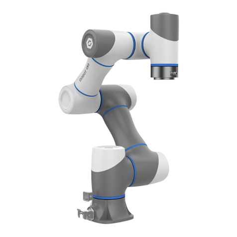
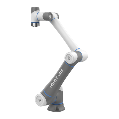
Dobot CR Series User manual

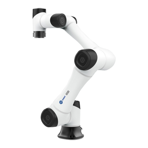
Dobot CR Series Robot
APP User Guide
Issue: V3.7
Date: 2020-11-13
Shenzhen Yuejiang Technology Co., Ltd

Dobot CR Series Robot APP User Guide
Issue V2 (2020-07-08) User Guide Copyright © Yuejiang Technology Co., Ltd
i
Precautions
Copyright © Shenzhen Yuejiang Technology Co., Ltd 2020. All rights reserved.
No part of this document may be reproduced or transmitted in any form or by any means
without the prior written consent of Yuejiang Technology Co., Ltd.
Disclaimer
To the maximum extent permitted by applicable law, the products described (including its
hardware, software, and firmware, etc.) in this document are provided AS IS, which may have
flaws, errors or faults. Yuejiang makes no warranties of any kind, express or implied, including but
not limited to, merchantability, satisfaction of quality, fitness for a particular purpose and
non-infringement of third party rights. In no event will Yuejiang be liable for any special,
incidental, consequential or indirect damages resulting from the use of our products and
documents.
Before using our product, please thoroughly read and understand the contents of this
document and related technical documents that are published online, to ensure that the robot is
used on the premise of fully understanding the robot and related knowledge. Please use this
document with technical guidance from professionals. Even if follow this document or any other
related instructions, Damages or losses will be happening in the using process, Dobot shall not be
considered as a guarantee regarding all security information contained in this document.
The user has the responsibility to make sure following the relevant practical laws and
regulations of the country, in order that there is no significant danger in the use of the robot.
Shenzhen Yuejiang Technology Co., Ltd
Address: Floor 9-10, Building 2, Chongwen Garden, Nanshan iPark, Liuxian Blvd, Nanshan
District, Shenzhen, Guangdong Province, China
Website: www.dobot.cc

Dobot CR Series Robot APP User Guide
Issue V2 (2020-07-08) User Guide Copyright © Yuejiang Technology Co., Ltd
ii

Dobot CR Series Robot APP User Guide
Issue V2 (2020-07-08) User Guide Copyright © Yuejiang Technology Co., Ltd
iii
Preface
Purpose
This Document describes how to use Dobot CR series robots with APP, making it easy for
users to fully understand and use it.
Intended Audience
This document is intended for:
Customer
Sales Engineer
Installation and Commissioning Engineer
Technical Support Engineer
Change History
Date
Change Description
2020/11/17
The first releases
Symbol Conventions
The symbols that may be founded in this document are defined as follows.
Symbol
Description
DANGER
Indicates a hazard with a high level of risk which, if
not avoided, could result in death or serious injury
WARNING
Indicates a hazard with a medium level or low level of
risk which, if not avoided, could result in minor or
moderate injury, robot damage
NOTICE
Indicates a potentially hazardous situation which, if
not avoided, can result in equipment damage, data
loss, or unanticipated result
NOTE
Provides additional information to emphasize or
supplement important points in the main text

Dobot CR Series Robot APP User Guide
Issue V2 (2020-07-08) User Guide Copyright © Yuejiang Technology Co., Ltd
1
Contents
Precautions.....................................................................................................................i
Preface..........................................................................................................................iii
Function Description of Software........................................................................... 3
Fast Connection.................................................................................................................. 5
Setting................................................................................................................................. 5
Set Jog................................................................................................................... 5
Set Playback.......................................................................................................... 6
Coor User.............................................................................................................. 7
Coor Tool.............................................................................................................10
Safe Set................................................................................................................13
Remote Control................................................................................................... 16
Robot Pose...........................................................................................................20
Installation...........................................................................................................21
Manufactory Set.................................................................................................. 22
Software Set........................................................................................................ 22
Process.............................................................................................................................. 25
Drag Teach...........................................................................................................25
Monitor..............................................................................................................................26
I/O Monitor..........................................................................................................26
Robot Status........................................................................................................ 28
Terminal...............................................................................................................28
Programming.....................................................................................................................31
Project Description..............................................................................................31
Program Description........................................................................................... 31
Program Example................................................................................................34
Program Language.................................................................................................40
Arithmetic Operators........................................................................................................ 40
Relational Operator...........................................................................................................40
Logical Operators..............................................................................................................40
General Keywords............................................................................................................ 41
General Symbol................................................................................................................ 41
Processing Control Commands.........................................................................................41
Global Variable................................................................................................................. 41
Motion Commands........................................................................................................... 42
Motion Parameter Commands.......................................................................................... 49
Six-axis Force Sensor Commands....................................................................................52
Input/output Commands................................................................................................... 54
Program Managing Commands........................................................................................ 56
Pose Getting Command.................................................................................................... 59
TCP................................................................................................................................... 60
UDP...................................................................................................................................64
Modbus..............................................................................................................................67
Dobot CR Series Robot APP User Guide
Issue V2 (2020-07-08) User Guide Copyright © Yuejiang Technology Co., Ltd
2
Modbus Register Description..............................................................................67
Command Description........................................................................................ 68

Dobot CR Series Robot APP User Guide
Issue V2 (2020-07-08) User Guide Copyright © Yuejiang Technology Co., Ltd
3
Function Description of Software
The robot supports Android/iOS tablet operation and PC operation. This manual uses Android
tablet as an example.
The interface is shown in Figure 1.1, and its detailed description is shown in Table 1.2.
Figure 1.1 Homepage
Table 1.1 Cable color description
NO.
Description
1
Click this button to go back to the previous page
2
Connection button
When device and robot arm are connected to network, click the
button to connect the device to robot arm
3
Alarm log
You can click it to check alarm log
4
Manager
APP login personnel are divided into observer, operator,
programmer and manager, different personnel can operate
different functions, including the most authority of the
management, can operate all functions
Observer: check the system status, I/O status, robot pose,
and alarms
Operator: Operate a robot based on the existing scripts
without programming
Programmer: Program, Teach

Dobot CR Series Robot APP User Guide
Issue V2 (2020-07-08) User Guide Copyright © Yuejiang Technology Co., Ltd
4
NO.
Description
Manager: Set parameters
5
Monitoring module shortcuts
6
Set speed ratio
7
Robotic arm enable button
The icon is green when robot motor is in the enabled status
Tshe icon is red when robot motor is in the disabled status
8
Emergency stop switch
Emergency stop switch can be pressed when robot arm is in
short of time during operation, to control servo drive power off
and robot arm stop urgently but constant power
9
System settings
Click this button to expand the page to view help
documentation, lock screen, switch skins, etc.
10
Jogging robotic arm
You can jogging the robot arm. Click the button to
switch the joint coordinate system or the Cartersin coordinate
system
11
Programming module
Programming modules are mainly used for editing and running
programs
12
Process
Support drag teaching, conveyor tracking
13
Setting
Set the related parameters of robot arm, including motion
parameters, coordinate system settings, calibration, etc.
14
Monitoring module
You can view the status of robot arm, set the output of I/O , set
the end parameters of robot arm and other functions
15
The 3D illustration of a robotic arm
NOTICE
The software supports the screen lock function. If the software has not been operated

Dobot CR Series Robot APP User Guide
Issue V2 (2020-07-08) User Guide Copyright © Yuejiang Technology Co., Ltd
5
for a long time, the screen is automatically locked. The unlock password is 000000 by
default.
Fast Connection
Prerequisites
The controller has been connected to the WiFi module.
The APP supports WiFi function.
Procedure
You can modify the WiFi password on the Setting > Software Set > WiFi Set page
with manager authority.
Setting
Before teaching or running robot programs, a series of settings are required, including motion
parameter setting, user mode selecting and process setting.
Set Jog
You can set the velocity, acceleration or other parameters in different coordinate systems with
programmer authority or manager authority when jogging a robot or running robot programs.
After setting the parameters, please click Save.
Set the maximum velocity and acceleration in Joint and Cartesian coordinate system when
jogging a robot. As shown in Figure 1.2.
Figure 1.2 Jogging parameters in the Joint coordinate system

Dobot CR Series Robot APP User Guide
Issue V2 (2020-07-08) User Guide Copyright © Yuejiang Technology Co., Ltd
6
Set Playback
Set the maximum velocity, acceleration, and jerk in the Joint and Cartesian coordinate system
when running robot programs, as shown in Figure 1.3.
Figure 1.3 Playback parameters
When doing jogging or playback, the method calculating the velocity and acceleration for
each axis (in Joint or Cartesian coordinate system) is shown as follows.
Actual jogging velocity = the maximum jogging velocity * global velocity rate
Actual jogging acceleration = the maximum jogging acceleration* global velocity
rate
Actual playback velocity = the maximum playback velocity * the set velocity rate
in the velocity function
Actual playback acceleration = the maximum playback acceleration * the set
acceleration rate in the acceleration function
Actual playback jerk = the maximum playback jerk * the set acceleration rate in the
jerk function
NOTE
The rates (velocity rate, acceleration rate, or jerk rate) can be set in the related speed
functions. For details, please see 2.9 Motion Parameter Commands.
If the motion mode is Jump when running robot programs, you need to set StartHeight,
EndHeight, and zLimit.
You can set 10 sets of Jump parameters. Please set and select any set of parameters for calling
Jump command during programming. As shown in Figure 1.4. Please refer to Table 2.24 for use

Dobot CR Series Robot APP User Guide
Issue V2 (2020-07-08) User Guide Copyright © Yuejiang Technology Co., Ltd
7
Figure 1.4 Jump parameters
Coor User
When the position of workpiece is changed or a robot program needs to be reused in multiple
processing systems of the same type, you can create coordinate systems on the workpiece to
simplify programming. There are totally 10 groups of User coordinate systems, of which the first
one is defined as the Base coordinate system by default and cannot be changed. And the others can
be customized by users.
NOTICE
When creating a User coordinate system, please make sure that the reference
coordinate system is the Base coordinate system.
Point: move TCP to any point Ato create origin, and create user coordinate system
according to the default tool coordinate system As shown in Figure 1.5.

Dobot CR Series Robot APP User Guide
Issue V2 (2020-07-08) User Guide Copyright © Yuejiang Technology Co., Ltd
8
Figure 1.5 Point
Line: Confirm a straight line by any two points Aand B. The direction from A to B is
defined as the positive direction of Y-axis, The Z-axis of Tool coordinate system of which
point A is the origin is projected into the vertical plane that confirmed by points A and point
B, we can define it as the positive direction of Z-axis. and then the positive direction X axis
can be defined based on the right-hand rule. As shown Figure 1.6.

Dobot CR Series Robot APP User Guide
Issue V2 (2020-07-08) User Guide Copyright © Yuejiang Technology Co., Ltd
9
Figure 1.6 Line
Area: User coordinate system is created by three-point calibration method. Move the
robot to three points A(x1, y1, z1),B(x2, y2, z2), and C(x3,y3,z3). Point A is defined as the
origin and the line from point A to Point B is defined as the positive direction of X-axis. The
line that point C is perpendicular to X-axis is defined as the position direction of Y-axis. And
then the Z-axis can be defined based on the right-handed rule, as shown in Figure 1.7.
Figure 1.7 Area

Dobot CR Series Robot APP User Guide
Issue V2 (2020-07-08) User Guide Copyright © Yuejiang Technology Co., Ltd
10
Take the establishment of User 1 coordinate system as an example.
Prerequisites
The robot has been powered on.
The robot is enabled.
The robot is in the Cartesian coordinate system.
The user's authority is programmer authority or manager authority.
Procedures
Figure 1.8 User coordinate system
Coor Tool
When an end effector such as welding gun, gripper is mounted on the robot, the Tool
coordinate system is required for programming and operating a robot. For example, you can use
multiple grippers to carry multiple workpieces simultaneously to improve the efficiency by setting

Dobot CR Series Robot APP User Guide
Issue V2 (2020-07-08) User Guide Copyright © Yuejiang Technology Co., Ltd
11
each gripper to a Tool coordinate system.
There are totally 10 groups of Tool coordinate systems. Tool 0 coordinate system is the
predefined Tool coordinate system which is located at the robot flange and cannot be changed.
NOTICE
When creating a Tool coordinate system, please make sure that the reference
coordinate system is the predefined Tool coordinate system.
Tool coordinate system is created by three-point calibration method (TCP +ZX): After the
end effector is mounted, please adjust the direction of the end effector, to make TCP (Tool Center
Point) align with the same point (reference point) in three different directions, for obtaining the
position offset of the end effector, and then jog the robot to the other three points (A,B,C) for
obtaining the angle offset, as shown in Figure 1.9.
Figure 1.9 Three points calibration method (TCP+ZX)
Take the establishment of Tool 1 coordinate system as an example.
Prerequisites
The robot has been powered on.
The robot is enabled.
The robot is in the Cartesian coordinate system.
The user's authority is programmer authority or manager authority.
Procedure

Dobot CR Series Robot APP User Guide
Issue V2 (2020-07-08) User Guide Copyright © Yuejiang Technology Co., Ltd
12
Figure 1.10 Tool Coordinate page
NOTE
Rx,Ry,Rz are the orientation data, which are designated by rotating the tool center
point (TCP) around the X, Y, Z axes under the selected Tool coordinate system.
The three points (A, B, C) cannot lie in the same line.
This step defines the X-axis, and the Y-axis can be defined based on the
right-handed rule.

Dobot CR Series Robot APP User Guide
Issue V2 (2020-07-08) User Guide Copyright © Yuejiang Technology Co., Ltd
13
Safe Set
In the safety setting module, you can set safety parameters such as collision detection, power
control, joint braking, etc.
This module must be operated with the programmer authority or manager authority.
1.2.5.1 Safe Collision
Collision detection is mainly used for reducing the impact on the robot arm, to avoid damage
to the robot arm or external equipment. If the collision detection is activated, the robot arm will
stop running automatically when the robot arm hits an obstacle.
You can enable collision detection function on the Setting > Safe Set > Safe Collision page
and set the collision level. Meanwhile, you can select Turn on automatic drag after collision,
namely, when the robot arm stops running after hitting an obstacle, you can drag robot to a safe
position.
Figure 1.11 Safety Hit
1.2.5.2 Electronic Skin
Electronic skin allows robot to respond in real time when robot meets an obstacle, helping
robot avoid obstacle during running.
You can enable electronic skin function on the Setting > Safe Set > Electronic skin page and
set the robot status when meeting an obstacle. For example, robot can bypass the obstacle or stop
running. You can also set the electronic skin parameters on this page

Dobot CR Series Robot APP User Guide
Issue V2 (2020-07-08) User Guide Copyright © Yuejiang Technology Co., Ltd
14
Figure 1.12 Safety Hit
Parameter
Description
Avoid speed
Range: 1~500, recommend value: 100
Avoid distance
Range: 0~200, recommend value: 80
Avoid acceleration
Range: 1~50000, recommend value:1000
Recovery speed
Range: 1~500, Recommend value: 100
Recovery acceleration
Range: 1~50000, Recommend value: 1000
1.2.5.3 Joint Brake
If you want to drag joints by hand, please enable the braking function. Namely, Open each
joint brake on the Setting > Safe Set > Joint brake page. When enable this function, please hold
the robot arm to avoid damage.

Dobot CR Series Robot APP User Guide
Issue V2 (2020-07-08) User Guide Copyright © Yuejiang Technology Co., Ltd
15
Figure 1.13 Joint brake
1.2.5.4 Power Control
When the emergency stop switch is pressed, the robot will power off. You can click Power
On on the Setting > Safe Set > Power control page to power on the robot. Also, you can power
off the robot on this page.
Figure 1.14 Power control
1.2.5.5 Terminal Load
To ensure optimum robot performance, it is important to make sure the load and inertia of the
end effector are within the maximum rating for the robot.

Dobot CR Series Robot APP User Guide
Issue V2 (2020-07-08) User Guide Copyright © Yuejiang Technology Co., Ltd
16
The load is weight of the end effector and work piece, which must not exceed the maximum
load. You can set the load on the Setting >Safe Set > Terminal load page.
Figure 1.15 Terminal load
Remote Control
External equipment can send commands to a robot by different remote control modes, such as
remote I/O mode and remote Modbus mode. The default mode is Teaching mode when the robot is
shipped out. When you need to set the remote mode, please set it on APP with the robot motor in
the disabled state.
NOTICE
Robot rebooting is not required when switching the remote mode.
The emergency stop switch on the hardware is always available no matter what
mode the robot system is in.
Please DO NOT switch the remote mode when the robot is running in the current
remote mode. You need to exit the current mode and then switch to the other
remote mode. Namely, please stop the robot running and then switch the mode.
1.2.6.1 Remote I/O
When the remote mode is I/O mode, external equipment can control a robot in this mode. The
specific I/O interface descriptions are shown in Table 1.2.
Table 1.2 Specific I/O interface description
I/O interface
Description
Input (For external control)
DI 11
Clear alarm
Other manuals for CR Series
1
Table of contents
Other Dobot Robotics manuals

Dobot
Dobot Magician Go DT-AC-GO4WD-01E User manual

Dobot
Dobot CR5 Installation manual

Dobot
Dobot Magician User manual

Dobot
Dobot Magician User manual

Dobot
Dobot PGC-50 User manual

Dobot
Dobot Conveyor Belt User manual

Dobot
Dobot CR12 Installation manual

Dobot
Dobot Magician User manual

Dobot
Dobot M1 Pro Installation manual

Dobot
Dobot CR5 User manual

Dobot
Dobot Magician Lite User manual

Dobot
Dobot MG400 Installation manual

Dobot
Dobot Magician Lite User manual

Dobot
Dobot CR A Series User manual

Dobot
Dobot M1 User manual

Dobot
Dobot M1 User manual

Dobot
Dobot AiStarter User manual

Dobot
Dobot CR3 Installation manual

Dobot
Dobot M1 User manual

Dobot
Dobot Magician User manual