Doepke DRO 1U User manual
3931195/03/10/F
Doepke
Dupline
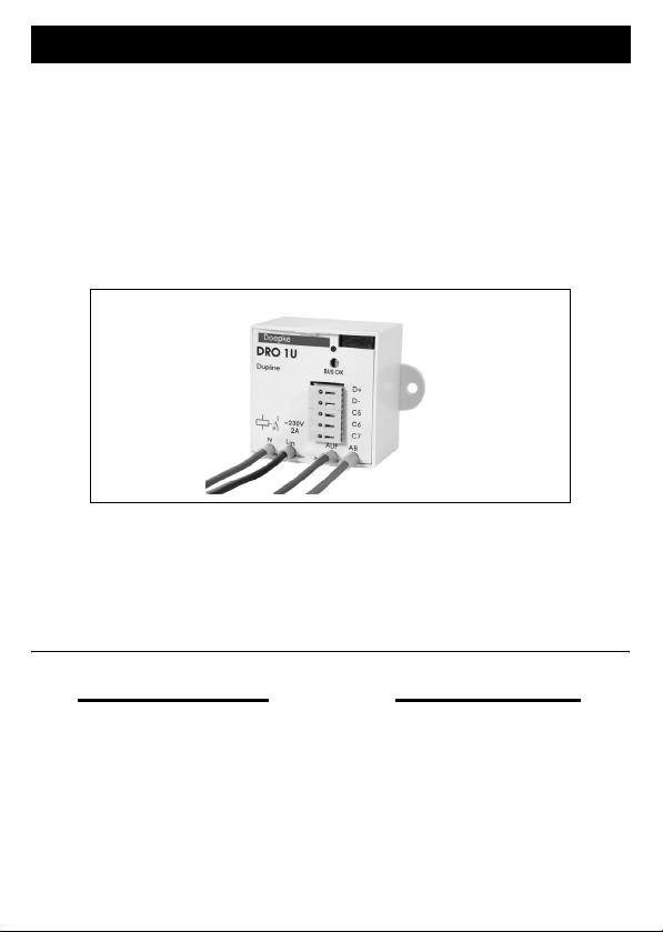
Rollladensteuergerät DRO 1U
mit 3 Halbleitereingängen
Shutter Control Unit DRO 1U
with 3 Semiconductor Inputs
Bedienungsanleitung
Operating Instructions
Inhaltsverzeichnis
1. Allgemeines.............................. 2
2. Kodierung................................. 2
3. Inbetriebnahme ........................ 3
4. Anzeigen .................................. 3
5. Technische Daten .................... 3
6. Garantie ................................... 4
13. Anschlussschema / Connection
Diagram.................................... 8
Table of Contents
7. General Information ................. 5
8. Coding...................................... 5
9. Putting into Service .................. 6
10. Indicators.................................. 6
11. Technical Data ......................... 6
12. Guarantee ................................ 7
13. Anschlussschema / Connection
Diagram.................................... 8
2 3931195/03/10/F
Doepke
Bedienungsanleitung
Dupline Rollladensteuergerät DRO 1U
1. Allgemeines
Das Rollosteuergerät DRO 1U ist eine Komponente des Dupline Installationssystems
und ermöglicht das Schalten eines Rollomotors oder auch Markisen- oder Dachfenster-
antriebes. Die Kontakte für Auf und Ab sind elektronisch und mechanisch im Gerät sowie
softwaremäßig im System verriegelt.
Das DRO 1U verfügt weiterhin über drei Eingänge, an denen beliebige, potenzialfreie
Tastkontakte angeschlossen werden können, um deren Signale dem Dupline-Netz zu-
zuführen. Die Betriebsversorgung erfolgt aus der Netzspannung, der Einbau kann de-
zentral, z.B. in Schalterdosen oder Rolladenkästen, erfolgen.
Die frontseitig angebrachte, grüne LED zeigt die ordnungsgemäße Arbeitsweise des Du-
pline-Busses an.
ACHTUNG!
Zur Steuerung der Antriebe ist es unbedingt notwendig, das ProLine-Objekt
„Rollladensteuerung“ zu verwenden, da sonst die erforderlichen Umschaltver-
zögerungen nicht eingehalten werden. Dies kann zur Beschädigung der
Relaiskontakte und der daran angeschlossenen Motoren führen.
Zudem ist die ständige Versorgung des Gerätes mit Netzspannung notwendig,
um die korrekte Funktionsweise sicher zu stellen.
2. Kodierung
Mit dem Handkodiergerät DHK 1 kann über den Flachsteckeranschluss an der Front des
DRO 1U jedem Kanal jede beliebige Adresse zwischen A1 und P8 zugeordnet werden.
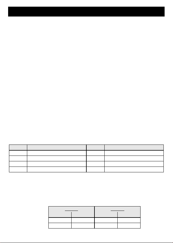
Die Aufteilung der Kanäle ist wie folgt:
Funktionen, die nicht benötigt werden, sollten unkodiert bleiben. Die Kodierung des
DRO 1U kann ohne Versorgungsspannung sowie ohne Dupline-Signal vorgenommen
werden. Sie bleibt dauerhaft erhalten, kann aber jederzeit überschrieben werden.
Die Adressvergabe muss in der Weise erfolgen, dass die Auf- und Ab-Funktion des Re-
lais zwei benachbarte Adressen erhalten. Es ist immer mit dem ungeraden Adresswert
zu beginnen.
Beispiel:
Kanal Beschreibung Kanal Beschreibung
1 Motor AUF 5 Eingang C5
2 Motor AB 6 Eingang C6
3 Nicht belegt 7 Eingang C7
4 Nicht belegt 8 Nicht belegt
Falsch Richtig
AUF AB AUF AB
G6 G7 M3 M4
P1 P6 P1 P2

3931195/03/10/F 3
Doepke
Die Vorzugsschaltrichtung bei Busausfall (“AUF” = 1 oder “AB” = 0) kann ebenfalls mit
dem Handkodiergerät eingestellt werden; standardmäßig ist “AUF” eingestellt.
3. Inbetriebnahme
Die Installation darf nur von einer autorisierten Fachkraft vorgenommen werden. Bei der
Installation ist das Anschlussschema zu beachten. Alle anzuschließenden Leitungen
müssen spannungsfrei sein.
Der Phaseneingang dient gleichzeitig zur Versorgung des Gerätes und der Schaltstufe.
Um Störungen zu vermeiden, sollte die Länge der Leitungen zwischen Taster und dem
DRO 1U bei normalen Umgebungsbedingungen 3 m, in industrieller Umgebung 1 m,
nicht überschreiten.
ACHTUNG!
Um identische Längen der Dupline Signalleiter zu gewährleisten, verlegen Sie
bitte immer beide Leiter (Dupline + und -) zu den Tastern bzw. Kontakten!
Als gemeinsames Potenzial ist der Dupline Signalleiter (Dupline -) zu nutzen. Dabei ist
die Verbindung direkt an der Klemme herzustellen. Folgende Tabelle zeigt die An-
schlussbelegung:
Verbindungen zwischen dem Dupline-Signal und dem Erdpotenzial führen zu Störungen
und sind nicht zulässig. Auf die richtige Polarität des Dupline-Signals ist zu achten.
Bedingt durch das interne Netzteil entwickelt das DRO 1U nach kurzer Betriebszeit eine
leichte Eigenerwärmung, die jedoch unbedenklich ist.
Um den Forderungen für Schutzkleinspannung zu genügen, ist bei der Installation die
VDE0100, Teil 410 zu beachten und anzuwenden. Netzkabel dürfen aus Sicherheits-
gründen nicht durch dieselbe Unterputzdose geführt werden.
4. Anzeigen
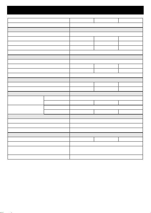
5. Technische Daten
Klemme Beschreibung Klemme Beschreibung
C5 Halbleitereingang C5 Braun Schaltkanal AUF
C6 Halbleitereingang C6 Braun Schaltkanal AB
C7 Halbleitereingang C7
D- Dupline Signalleiter - (Dupline-) Schwarz Phaseneingang (LIN)
D+ Dupline Signalleiter + (Dupline+) Blau Neutralleiter (N)
Anzeige Beschreibung
Grüne „BUS OK“-
LED
Dupline-Bus:
Aus: Busstörung / An: Bus OK
Min. Typ. Max.
Dupline
Stromaufnahme 10 µA
Eingangskanäle 3 (Halbleitereingänge C5/C6/C7)
4 3931195/03/10/F
Doepke
6. Garantie
Für fachgerecht montierte, unveränderte Geräte gewähren wir ab Kauf durch den End-
verbraucher die gesetzliche Gewährleistungsfrist. Die Garantie bezieht sich nicht auf
Transportschäden sowie Schäden, die durch Kurzschluss oder Überlastung entstanden
sind. Bei Fertigungs- und Materialfehlern, die innerhalb der Gewährleistungsfrist erkannt
werden, leistet unser Werk kostenlosen Ersatz. Bei Öffnen des Gerätes erlischt der Ga-
rantieanspruch.
Ausgangskanäle 2 Steuerkanäle (Rollo „AUF“ und „AB“)
Eingänge
Art Halbleitereingänge
Steuerstrom 1 mA
Erlaubte Tastprellzeit 10 ms
Kontaktinnenwiderstand 1 kOhm
Erlaubte Leitungslänge 3 m (in industrieller Umgebung: 1 m)
Ausgänge
Art Schaltrelais
Nennspannung 230 VAC
Nennstrom 2 A
Leistungsfaktor cos ϕ = 0,6 - 1
Betriebsspannung
Nennbetriebsspannung 210 VAC 230 VAC 250 VAC
Stromaufnahme 8 mA 10 mA 12 mA
Anschlüsse
Steueranschlüsse Art 2- und 3-polige Steckklemmen (montiert)
Klemmbereich 0,6 mm ∅0,8 mm ∅
Netzanschlüsse Art 4 Leitungen LiY mit Aderendhülsen
Klemmbereich 0,75 mm²
Gehäuse
Art Laschengehäuse
Maße 42 x 42 x 34 (B x H x T in mm)
Material Polyamid PA6
Allg. technische Daten
Betriebstemperatur -10°C +35°C
Luftfeuchtigkeit max. 85% (Betauung nicht zulässig)
Schutzart / Normen IEC60669, EN55022 / EN50081-1 und
EN55024 / EN50082-1
Bestellnummer, -bezeichnung 09 501 138, Rollladensteuerung DRO 1U
Min. Typ. Max.

3931195/03/10/F 5
Doepke
Operating Instructions
Dupline Shutter Control Unit DRO 1U
7. General Information
The DRO 1U shutter control unit is a component of the Dupline installation system and
permits the control of shutter motors or drives of blinds or skylights. The contacts for Up
and Down movement are locked electronically and mechanically in the unit as well as by
the system software.
In addition, the DRO 1U is equipped with three inputs to which any electrically isolated
control contacts can be connected in order that their signals can be transmitted to the
Dupline net. As it is supplied by mains voltage, it can be fitted in a convenient local po-
sition, e.g. in switch socket boxes or shutter housings.
The green LED on the front indicates the proper functioning of the Dupline bus.
CAUTION!
For the control of motors it is absolutely necessary to use the ProLine
object „Roller blind“, since otherwise the required reverse delays cannot
be kept. This may lead to damages at the relay contacts and the motors
connected to them.
In addition, a permant supply of the device with voltage is necessary to
ensure proper functionality.
8. Coding
With the DHK 1 hand encoder each channel can be assigned any address between A1
and P8 via the flat-plug connector on the front of the DRO 1U. The allocation of the chan-
nels is as follows:
Functions which are not required should remain uncoded. Encoding the DRO 1U requi-
res neither a supply voltage nor the Dupline signal. Although the coding is permanently
retained, it may always be overwritten.
Addresses should be assigned in such a way that the Up and Down functions of the relay
receive adjoining addresses. You should always start with an uneven address figure.
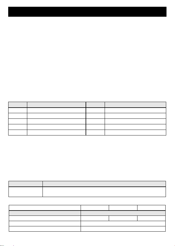
Example:
The preferred switching direction in the event of a bus fault (“UP” = 1 or “DOWN” = 0)
Channel Description Channel Description
1 Motor UP 5 Input C5
2 Motor DOWN 6 Input C6
3 Not assigned 7 Input C7
4 Not assigned 8 Not assigned
Wrong Right
UP DOWN UP DOWN
G6 G7 M3 M4
P1 P6 P1 P2
6 3931195/03/10/F
Doepke
can also be preset with the hand encoder; the standard setting is „UP”.
9. Putting into Service
Installation may only be carried out by an authorized technician. Observe the connection
diagram when installing. All leads to be connected must be dead.
The phase input serves to supply the unit as well as the actuating output.
In order to avoid malfunctions, the length of the line between push-button and the
DRO 1U should not exceed 3 m under normal environmental conditions and 1 m in in-
dustrial environments.
OBSERVE!
In order to make sure that the Dupline signal conductors have identical length,
please always lay both leads (Dupline + and -) towards the push buttons or
contacts!
The Dupline signal conductor (Dupline -) should be used as common potential, with the
connection being made directly at the terminal. The following table illustrates the connec-
tion configuration:
Connections between the Dupline signal and earth potential will cause malfunctions and
are not permissible. Attention should be paid to the correct polarity of the Dupline signal.
Because of the integrated power pack, the DRO 1U will warm up slightly after a short run-
ning time. This is, however, no cause for concern.
In order to meet the requirements for protective low voltage, VDE0100, Part 410, should
be observed and put into practice during installation. For safety reasons mains cables
may not be routed through the same installation box.
10. Indicators
11. Technical Data
Terminal Description Terminal Description
C5 Semiconductor input C5 Brown Switching channel „UP“
C6 Motor 2 output (DOWN/UP) Brown Switching channel „DOWN“
C7 Motor 3 output (UP/DOWN)
D- Dupline signal conductor - Black Phase input (LIN)
D+ Dupline signal conductor + Blue Neutral (N)
Indicator Description
Green “BUS OK”
LED
Dupline bus:
Off - bus fault / On - bus OK
Min. Typ. Max.
Dupline
Current input 10 µA
Input channels 3 (semiconductor inputs C5/C6/C7)
Output channels 2 control channels (shutter „UP“ und „DOWN“)

3931195/03/10/F 7
Doepke
12. Guarantee
All professionally installed, unaltered devices are covered by warranty during the statu-
tory guarantee period from the day of purchase by the end user. The guarantee is not
applicable to damage incurred during transport or caused by short-circuit or overloading.
In the event of defects in workmanship or material, which are discovered within the gua-
rantee period, the company will provide a replacement free of charge. The guarantee will
be rendered null and void if the device is opened or tampered with.
Inputs
Type semiconductor inputs
Contact load 1 mA
Permissible switch bounce time 10 ms
Permissible inh. contact resistance 1 kOhm
Permissible line length 3 m (in industrial environment: 1 m)
Outputs
Type Switching relays
Rated voltage 230 VAC
Rated current 2 A
Power factor cos ϕ = 0.6 - 1
Operating voltage
Rated operating voltage 210 VAC 230 VAC 250 VAC
Current input 8 mA 10 mA 12 mA
Terminals
Control terminals Type 2- and 3-pole plug terminals (fitted)
Contact area 0.6 mm ∅0.8 mm ∅
Mains terminals Type 4 leads LiY with wire end ferrules
Contact area 0.75 mm²
Housing
Type Strap-type enclosure
Dimensions 42 x 42 x 34 (W x H x D in mm)
Material Polyamide PA6
General technical data
Operating temperature -10°C +35°C
Atm. humidity max. 85% (exposure to dew not permissible)
Encl. protection type/standards IEC60669, EN55022 / EN50081-1 and
EN55024 / EN50082-1
Order number, description 09 501 138, Shutter control unit DRO 1U
Min. Typ. Max.
8 3931195/03/10/F
Doepke
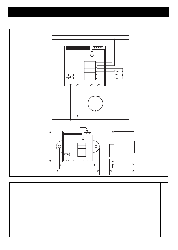
13. Anschlussschema / Connection Diagram
Sollten Sie Fragen zu diesem Produkt
oder zum Dupline-System haben, wen-
den Sie sich bitte an:
In case of queries concerning this
product or the Dupline system plea-
se contact:
Doepke
Schaltgeräte GmbH & Co. KG
Stellmacherstraße 11
D-26506 Norden, Germany
Tel.: +49 (0) 4931/1806-0
Fax: +49 (0) 4931/1806-101
E-mail:
Internet:
http://www.doepke.de
3931195/03/10/F
Dupline
Doepke
DRO 1U
DRO 1U
~230V
2A
~230V
2A
µ
BUS OK
BUS OK
NAB
C7
C6
C5
D-
D+
Lin
Lin
AUF
Dupline +
Dupline -
L
N
M
schwarz / black
blau / blue
braun
brown
braun
brown
3931195_1B
42 mm
Dupline
Doepke
DRO 1U
DRO 1U
~230V
2A
~230V
2A
µ
BUS OK
BUS OK
NAB
C7
C6
C5
D-
D+
Lin
Lin
AUF
Anschluss für DHK 1
Connector for DHK 1
50 mm
59 mm
30 mm
34 mm
3931195_2C
Table of contents
Languages:
Other Doepke Control Unit manuals


Popular Control Unit manuals by other brands

Festo
Festo Compact Performance CP-FB6-E Brief description

Elo TouchSystems
Elo TouchSystems DMS-SA19P-EXTME Quick installation guide

JS Automation
JS Automation MPC3034A user manual

JAUDT
JAUDT SW GII 6406 Series Translation of the original operating instructions

Spektrum
Spektrum Air Module System manual

BOC Edwards
BOC Edwards Q Series instruction manual

KHADAS
KHADAS BT Magic quick start

Etherma
Etherma eNEXHO-IL Assembly and operating instructions

PMFoundations
PMFoundations Attenuverter Assembly guide

GEA
GEA VARIVENT Operating instruction

Walther Systemtechnik
Walther Systemtechnik VMS-05 Assembly instructions

Altronix
Altronix LINQ8PD Installation and programming manual


