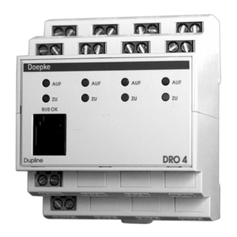
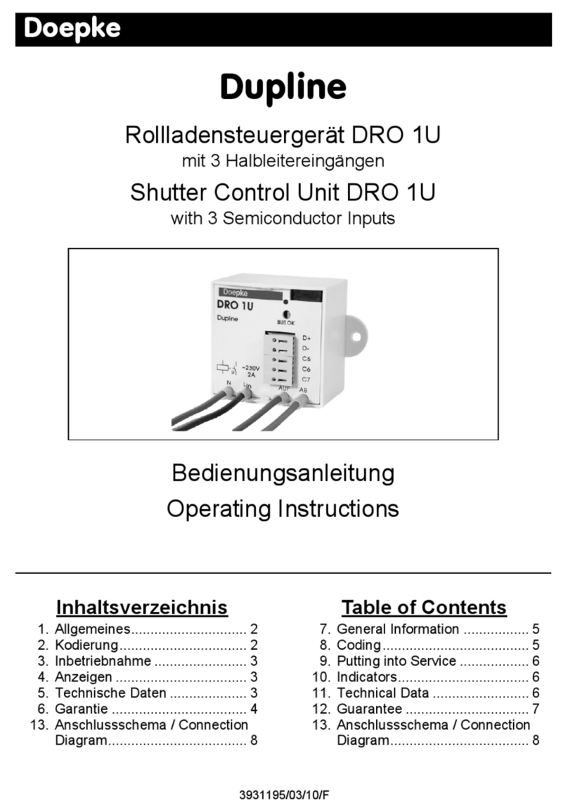
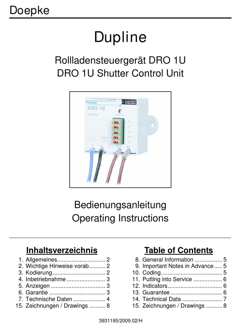
Doepke Dupline DRO 4b User manual

3931270/05/12/B
Doepke
Dupline
Rollladensteuergeräte DRO 4b/DRO 4c
DRO 4b/DRO 4c Shutter Control Units
Bedienungsanleitung
Operating Instructions

Sollten Sie Fragen zu diesem Produkt oder
zum Dupline-System haben, wenden Sie
sich bitte an:
In case of queries concerning this
product or the Dupline system please
contact:
Doepke
Schaltgeräte GmbH & Co. KG
Stellmacherstraße 11
D-26506 Norden, Germany
Tel.: +49 (0) 4931/1806-0
Fax: +49 (0) 4931/1806-101
E-mail:
Internet:
http://www.doepke.de
23931270/05/12/B - Technische Änderungen vorbehalten!
Doepke
Inhaltsverzeichnis
1. Allgemeines.......................................................................................................... 3
2. Kodierung ............................................................................................................. 3
3. Inbetriebnahme .................................................................................................... 4
4. Anzeigen ............................................................................................................... 5
5. Garantie ................................................................................................................ 5
6. Technische Daten ................................................................................................ 6
Table of Contents
7. General Information ............................................................................................. 7
8. Coding................................................................................................................... 7
9. Putting into Service ............................................................................................. 8
10. Guarantee ............................................................................................................. 9
11. Indicators.............................................................................................................. 9
12. Technical Data.................................................................................................... 10
13. Zeitverhalten Step-Betrieb / Timing Step-Mode (DRO 4c).............................. 11
14. Anschlussschema / Connection Diagram .......................................................12

3931270/05/12/B - Technische Änderungen vorbehalten! 3
Doepke
Deutsch
1- Inhaltsverz eichnis
Bedienungsanleitung
Rollladensteuergeräte DRO 4b/DRO 4c
1. Allgemeines
Die Rollosteuergeräte DRO 4b und DRO 4c sind Komponenten des Dupline Installati-
onssystems und ermöglichen das Schalten von vier unabhängigen Rollomotoren oder
auch Markisen- oder Dachfensterantrieben.
Diese Rollosteuergeräte der zweiten Generation (erkennbar an den Auf- und Ab-Pfeilen
auf der Frontbedruckung) sind mit einem Mikro-Controller ausgestattet - er stellt sicher,
dass selbst bei einer fehlerhaften Konfiguration der Kanalgeneratoren die erforderliche
Umschalttotzeit von 500 ms eingehalten werden.
Während das DRO 4b den „klassischen“ Betrieb der Rollläden und Dachfenster ermög-
licht, stellt das DRO 4c einen „Step-Betrieb“ zur Verstellung von Jalousien mit Lamellen
zur Verfügung. Bei Letzterem sollte daher von der Verwendung der Option „Lamellen-
verstellung“ im ProLine-Objekt „Rollladensteuerung“ abgesehen werden.
Hinweis: Bei der Verwendung des DRO 4c beachten Sie bitte unbedingt folgende
Punkte:
• Nicht jeder Antrieb eignet sich für den Step-Betrieb. Betreiben Sie das
DRO 4c deshalb nur mit solchen Antrieben, die - laut Hersteller - auch bei
häufigem Pulsen mit 100 ms Dauer keinen Schaden nehmen.
• Aufgrund der Vielzahl unterschiedlichster Ausführungen von Jalousien kann
eine einwandfreie Lamellenverstellung nicht grundsätzlich garantiert werden.
Im Zweifelsfall sollte das Zusammenspiel zwischen DRO 4c und Jalousie vor-
ab überprüft werden.
2. Kodierung
Mit dem Handkodiergerät DHK 1 kann über die Modularbuchse an der Front des DRO 4
jedem Schaltkanal jede beliebige Adresse zwischen A1 und P8 zugeordnet werden. Die
Kanalzuordnung ist wie folgt:
Funktionen, die nicht benötigt werden, sollten unkodiert bleiben. Die Kodierung des
DRO 4 kann ohne Versorgungsspannung sowie ohne Dupline-Signal vorgenommen
werden. Sie bleibt dauerhaft erhalten, kann aber jederzeit überschrieben werden.
Die Adressvergabe muss in der Weise erfolgen, dass die Auf- und Ab-Funktion eines
Motors zwei benachbarte Adressen erhalten. Es ist immer mit dem ungeraden Adress-
wert zu beginnen.
Kanal Beschreibung Kanal Beschreibung
1 Motor 1 AUF 5 Motor 3 AUF
2 Motor 1 AB 6 Motor 3 AB
3 Motor 2 AUF 7 Motor 4 AUF
4 Motor 2 AB 8 Motor 4 AB

43931270/05/12/B - Technische Änderungen vorbehalten!
Doepke
Deutsch
Beispiel:
Die Vorzugsschaltrichtung bei Busausfall (“AUF”, “AB”, oder keine Bewegung) kann
ebenfalls mit dem Handkodiergerät in Abhängigkeit der Brücke A-B für alle Relais ge-
meinsam eingestellt werden; standardmäßig ist die Brücke eingelegt und die Vorzugs-
richtung “AUF” (Kanalwert „1“) eingestellt. Durch die Einstellung des Wertes „0“ aktiviert
das DRO 4 bei Busausfall und eingelegter Brücke die Fahrtrichtung „AB“.
Wenn Sie die Brücke A-B entfernen, aktiviert das DRO 4 die Motoren bei Busausfall
nicht.
3. Inbetriebnahme
3.1. Anschlüsse
Die Installation darf nur von einer autorisierten Fachkraft vorgenommen werden. Bei der
Installation ist das Anschlussschema zu beachten. Alle anzuschließenden Leitungen
müssen spannungsfrei sein. Folgende Tabelle zeigt die Anschlussbelegung:
Verbindungen zwischen dem Dupline-Signal und der 24 V-Versorgung oder Verbindun-
gen zum Erdpotenzial führen zu Störungen und sind nicht zulässig. Auf die richtige Po-
larität der Versorgungsspannung und des Dupline-Signals ist zu achten.
Um den Forderungen für Schutzkleinspannung zu genügen, ist bei der Installation die
VDE 0100, Teil 410, zu beachten und anzuwenden.
Bitte achten Sie beim Anschluss darauf, dass das maximale Drehmoment der Klemmen
von 0,6 Nm nicht überschritten wird.
Falsch Richtig
AUF AB AUF AB
Motor 1 G6 G7 M3 M4
Motor 4 L5 P1 H7 H8
Klemme Beschreibung Klemme Beschreibung
1.1 Motor 1 AUF („↑“) 1.2 Phaseneingang Motor 1 (LIN1)
1.5 Motor 1 AB („↓“) 1.6 Phaseneingang Motor 1 (LIN1)
2.1 Motor 2 AUF („↑“) 2.2 Phaseneingang Motor 2 (LIN2)
2.5 Motor 2 AB („↓“) 2.6 Phaseneingang Motor 2 (LIN2)
3.1 Motor 3 AUF („↑“) 3.2 Phaseneingang Motor 3 (LIN3)
3.5 Motor 3 AB („↓“) 3.6 Phaseneingang Motor 3 (LIN3)
4.1 Motor 4 AUF („↑“) 4.2 Phaseneingang Motor 4 (LIN4)
4.5 Motor 4 AB („↓“) 4.6 Phaseneingang Motor 4 (LIN4)
A-B
4.4/4.8
Mit Brücke: Vorrangaauf/ab
Ohne: Keine Bewegung
a.Bei Busausfall - siehe auch Kapitel 2 “Kodierung”.
1.3 Dupline Signalleiter - (Dupline-)
1.7 Dupline Signalleiter + (Dupline+)
1.4 0 VDC Betriebsspannung 1.8 +24 VDC Betriebsspannung

3931270/05/12/B - Technische Änderungen vorbehalten! 5
Doepke
Deutsch
Das patentierte Schnappsystem erlaubt ein einfaches Entfernen des Gerätes von der
Hutschiene indem das Gehäuse bis zum Ausrasten hochgeschoben wird.
3.2. „Step-Betrieb“ (nur DRO 4c)
Das DRO 4c verfügt über eine Automatik, die die Verstellung der Lamellen von Jalousi-
en erleichtert. Generell schaltet das Gerät in den sogenannten „Step-Betrieb“, wenn Sie
den Auf-Befehl für längstens 1 Sekunde aktivieren und unmittelbar darauf (innerhalb
von max. 2 s) den Ab-Befehl geben. In diesem Fall beginnt das DRO 4c in Ab-Richtung
mit einem Puls-Pause-Verhältnis von 100 ms:900 ms zu takten. Entsprechendes gilt
natürlich für die Gegenrichtung.
Ein ausführliches Zeitdiagramm finden Sie in Kapitel 13 ”Zeitverhalten Step-Betrieb / Ti-
ming Step-Mode (DRO 4c)” auf Seite 11.
Hinweis: Da beim DRO 4c die Lamellenverstellung hardware-technisch realisiert ist,
sollten Sie die Option „Lamellenverstellung in ProLine bzw. ProLineNG
abschalten.
Durch die Erhöhung der „Umschaltzeit“ auf 2000 ms in der Konfiguration des Objekts
„Rollladensteuerung“ können Sie den Step-Betrieb für einzelne Ausgänge des DRO 4c
ausschalten.
4. Anzeigen
5. Garantie
Für fachgerecht montierte, unveränderte Geräte gewähren wir ab Kauf durch den End-
verbraucher die gesetzliche Gewährleistungsfrist. Die Garantie bezieht sich nicht auf
Transportschäden sowie Schäden, die durch Kurzschluss oder Überlastung entstanden
sind. Bei Fertigungs- und Materialfehlern, die innerhalb der Gewährleistungsfrist erkannt
werden, leistet unser Werk kostenlosen Ersatz. Bei Öffnen des Gerätes erlischt der Ga-
rantieanspruch.
Anzeige Beschreibung
Grüne „BUS OK“-LED Dupline-Bus:
Aus: Busstörung / An: Bus OK
4 rote LED „↑“Motoren 1 / 2 / 3 / 4:
Aus: keine Aufwärtsbewegung / An: Aufwärtsbewegung
4 rote LED „↓“Motoren 1 / 2 / 3 / 4:
Aus: keine Abwärtsbewegung / An: Abwärtsbewegung

63931270/05/12/B - Technische Änderungen vorbehalten!
Doepke
Deutsch
6. Technische Daten
Min. Typ. Max.
Dupline
Stromaufnahme 10 µA
Eingangskanäle Keine
Ausgangskanäle 8 Steuerkanäle (Rollo 1/2/3/4, je „AUF“ und „AB“)
Ausgänge
Art Schaltrelais
Nennspannung 230 VAC
Nennstrom (pro Ausgang) 2 A
Leistungsfaktor cos ϕ = 0,6 - 1
Step-Betrieb (nur DRO 4c)
Taktung Puls: 100 ms, Pause: 900 ms
Betriebsspannung
Nennbetriebsspannung 21,5 VDC 24 VDC 26,5 VDC
Stromaufnahme 6 mA 56 mA
Erlaubte Brummspannung 100 mVpp
Anschlüsse
Art Zugbügelklemmen
Klemmbereich 0,4 mm ∅2,5 mm²
Drehmoment 0,6 Nm
Gehäuse
Art Verteilereinbaugehäuse nach DIN 43880 für Hutschie-
nenmontage nach DIN EN 50022
Maße 72 x 85 x 58 (B x H x T in mm) / 4 TE
Material Polycarbonat
Allg. technische Daten
Betriebstemperatur -10°C +45°C
Luftfeuchtigkeit max. 85% (Betauung nicht zulässig)
Schutzart / Normen IEC 60669, EN 55022 / EN 50081-1 und EN 55024 /
EN 50082-1
Bestellnummer, -bezeichnung 09 501 214, Rollladensteuerung DRO 4b
09 501 215, Rollladensteuerung DRO 4c

3931270/05/12/B - The right to make technical changes reserved! 7
Doepke
English
1- Table of Co ntents
Operating Instructions
DRO 4b/DRO 4c Shutter Control Units
7. General Information
The shutter control units DRO 4b and DRO 4c are components of the Dupline building
management system and allow switching up to four independent shutters as well as
sunblinds or electrical dormers.
These second-generation shutter control units (identified by the Up and Down arrows
printed on the front panel) are equipped with a micro-controller which ensures that even
with an incorrect channel generator configuration the required reverse idle time of
500 ms is maintained.
While the DRO 4b is designed for the 'classic' control of shutters and skylights, the
DRO 4c offers a 'Step-Mode' feature for adjusting louvered blinds or shutters with slats.
When using the latter model the option "Tilting Blinds" in the ProLine object "Roller
blind" should therefore not be activated.
Note: Please be sure to observe the following points when using the DRO 4c:
• Not every drive is suitable for the step-mode. Therefore, operate the DRO 4c
only with those drives which - according to their manufacturer - will not be
damaged by frequent pulsing of 100 ms duration.
• Due to the wide range of different shutters and blinds perfect slat adjustment
cannot be guaranteed in every case. If in doubt check the interaction between
DRO 4c and blinds beforehand.
8. Coding
With the hand encoder DHK 1 each channel can be assigned any address between A1
and P8 using the modular plug at the front of the DRO 4. The channel allocation is as
follows:
Channels, which are not used, should not be encoded. The encoding of the DRO 4 can
be done without operating voltage and without any connection to the Dupline bus. The
encoding remains permanently but can be overwritten at any time.
The address assignment has to be done in that way, that the channels for the UP and
DOWN directions of each motor get consecutive addresses. It is always necessary to
start with an odd address.
Channel Description Channel Description
1 Motor 1 UP 5 Motor 3 UP
2 Motor 1 DOWN 6 Motor 3 DOWN
3 Motor 2 UP 7 Motor 4 UP
4 Motor 2 DOWN 8 Motor 4 DOWN

83931270/05/12/B - The right to make technical changes reserved!
Doepke
English
Example:
The priority drive direction in the event of a bus fault ("UP", "DOWN" or no movement)
can also be preset for all relays with the hand encoder depending upon the A-B bridge.
Normally this bridge is inserted and the priority direction is "UP" (channel setting "1"). If
"0" is set, the DRO 4 will - in the event of a bus fault - activate the drive direction "DOWN"
provided the bridge is in place.
If the A-B bridge is removed, the DRO 4 will not activate the motors when a bus fault oc-
curs.
9. Putting into Service
9.1. Connections
Only an authorized expert is allowed to carry out the installation. When installing, the
connection diagram has to be observed. All conductors that shall be connected have to
be free of voltage. Following table shows the connections:
Short circuits between Dupline signal conductors and the 24 V operating voltage or con-
nections to the grounding lead to malfunction and are not allowed. The correct polarity
of operating voltage and Dupline signal conductors has to be ensured.
In order to meet the requirements for protective low voltage, VDE 0100, Part 410, should
be observed and put into practice during installation.
When connecting please observe that the maximum torque of the terminals of 0.6 Nm
Wrong Right
UP DOWN UP DOWN
Motor 1 G6 G7 M3 M4
Motor 4 L5 P1 H7 H8
Terminal Description Terminal Description
1.1 Motor 1 output UP („↑“) 1.2 Phase input motor 1 (LIN1)
1.5 Motor 1 output DOWN („↓“) 1.6 Phase input motor 1 (LIN1)
2.1 Motor 2 output UP („↑“) 2.2 Phase input motor 2 (LIN2)
2.5 Motor 2 output DOWN („↓“) 2.6 Phase input motor 2 (LIN2)
3.1 Motor 3 output UP („↑“) 3.2 Phase input motor 3 (LIN3)
3.5 Motor 3 output DOWN („↓“) 3.6 Phase input motor 3 (LIN3)
4.1 Motor 4 output UP („↑“) 4.2 Phase input motor 4 (LIN4)
4.5 Motor 4 output DOWN („↓“) 4.6 Phase input motor 4 (LIN4)
A-B
4.4/4.8
Jumper fitted: Preferred di-
rectiona„Up“ or „Down“
Not fitted: No movement
a.On bus fault - please see chapter 8 “Coding”.
1.3 Dupline signal conductor - (Dupline-)
1.7 Dupline signal conductor +
(Dupline+)
1.4 0 VDC operating voltage 1.8 +24 VDC operating voltage

3931270/05/12/B - The right to make technical changes reserved! 9
Doepke
English
will not be exceeded.
The patented click-and-lock-mechanism allows an easy removal of the unit from the rail
by pushing the housing upwards until it is released.
9.2. „Step-Mode" (DRO 4c only)
The DRO 4c is provided with an automatic feature which facilitates the slat adjustment
of blinds and shutters. The unit will generally switch to the so-called "Step-Mode" if the
UP command is activated for no more than 1 second and the DOWN command is given
immediately afterwards (within max. 2s). The DRO 4c then starts to pulse in the DOWN
direction with a pulse-pause ratio of 100 ms:900 ms. And the same applies correspond-
ingly for the opposite direction of course.
A detailed timing diagram is provided in Chapter 13 “Zeitverhalten Step-Betrieb / Timing
Step-Mode (DRO 4c)” on page 11.
Note: As the actual slat adjustment with the DRO 4c is carried out by hardware,
the "Tilting Blinds" option in ProLine or ProLineNG should be deselected.
By increasing the „Reverse Delay“ to 2000 ms in the configuration of the object „Shutter
Control“, you may disable the step mode for single outputs.
10. Guarantee
All professionally installed, unaltered devices are covered by warranty during the statu-
tory guarantee period from the day of purchase by the end user. The guarantee is not
applicable to damage incurred during transport or caused by short-circuit or overloading.
In the event of defects in workmanship or material, which are discovered within the guar-
antee period, the company will provide a replacement free of charge. The guarantee will
be rendered null and void if the device is opened or tampered with.
11. Indicators
Indicator Description
Green “BUS OK” LED Dupline bus:
Off - bus fault / On - bus OK
4 red LED „↑“All-or-nothing relay 1 / 2 / 3 / 4:
Off - no upward movement / On - upward movement
4 red LED „↓“All-or-nothing relay 1 / 2 / 3 / 4:
Off - no downward movement / On - downward movement

10 3931270/05/12/B - The right to make technical changes reserved!
Doepke
English
12. Technical Data
Min. Typ. Max.
Dupline
Current input 10 µA
Input channels None
Output channels 8 control channels (shutters 1/2/3/4, each „Up“ and
„Down“)
Outputs
Type All-or-nothing relay
Voltage 230 VAC
Rated current / load capacity 2 A
Power factor cos ϕ = 0.6 - 1
Step Mode (DRO 4c only)
Timing Pulse: 100 ms; Pause: 900 ms
Operating Voltage
Rated operating voltage 21.5 VDC 24 VDC 26.5 VDC
Current input 6 mA 56 mA
Ripple voltage 100 mVpp
Terminals
Type Strain-relief clamps
Contact area 0.4 mm ∅2.5 mm²
Torque 0.6 Nm
Housing
Type Distribution installation housing to DIN 43880 for rail-
mounting to DIN EN 50022
Dimensions 72 x 85 x 58 (W x H x D in mm) / 4 modules
Material Polycarbonate
General technical data
Ambient temperature -10°C +45°C
Atm. humidity max. 85% (exposure to dew not permissible)
Encl. protection type /
standards
IEC 60669, EN 55022 / EN 50081-1 and EN 55024 /
EN 50082-1
Order number, description 09 501 214, Shutter Control Unit DRO 4b
09 501 215, Shutter Control Unit DRO 4c

3931270/05/12/B - The right to make technical changes reserved! 11
Doepke
Anschlüsse / Connections
13. Zeitverhalten Step-Betrieb / Timing Step-Mode (DRO 4c)
Auf-Taster
Push button „Up“
Ab-Taster
Push button „Down“
Relais „Auf“
Relay „Up“
Relais „Ab“
Relay „Down“
Auf-Taster
Push button „Up“
Ab-Taster
Push button „Down“
Relais „Auf“
Relay „Up“
Relais „Ab“
Relay „Down“

12 3931270/05/12/B - The right to make technical changes reserved!
Doepke
Anschlüsse / Connections
14. Anschlussschema / Connection Diagram
This manual suits for next models
1
Table of contents
Languages:
Other Doepke Control Unit manuals
Popular Control Unit manuals by other brands

oventrop
oventrop Regufloor HX Installation and operating instructions for the specialised installer

Yamaha
Yamaha RCX series user manual

Pentair
Pentair F783E operating manual

DELTA DORE
DELTA DORE DELTA 8000 BT installation instructions

Samson
Samson 3251 Mounting and operating instructions

GEM
GEM 543 eSyStep operating instructions