manuals.online logo
Brands
  1. Home
  2. •
  3. Brands
  4. •
  5. Monacor
  6. •
  7. Control Unit
  8. •
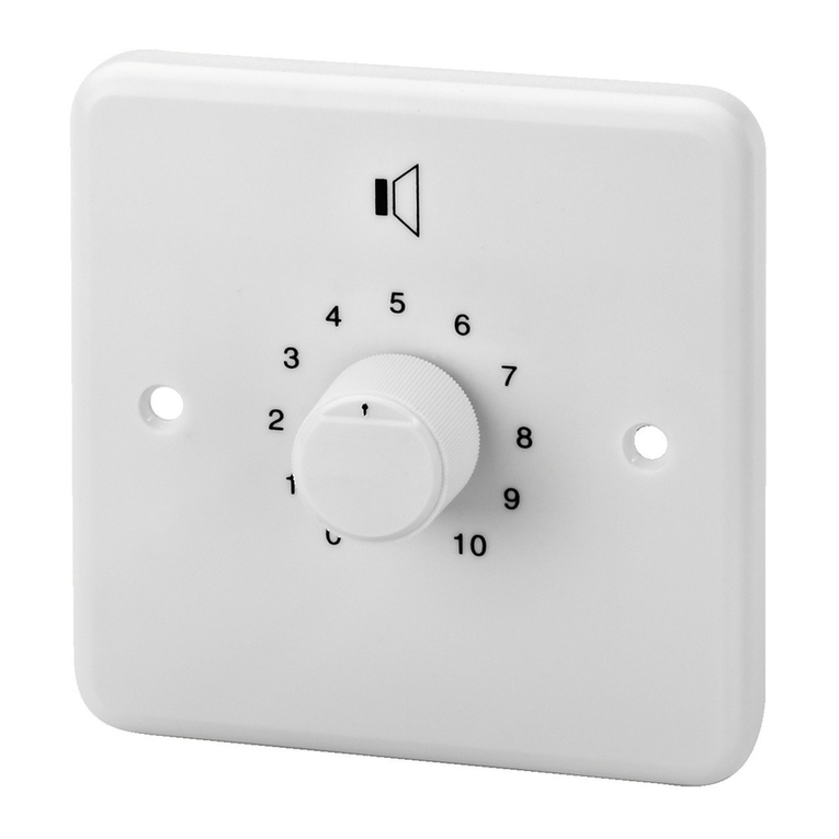
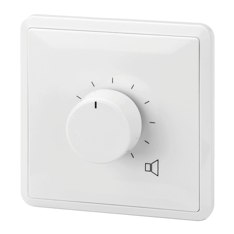
  9. Monacor ATT-212/WS User manual

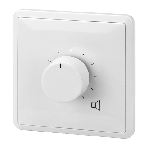
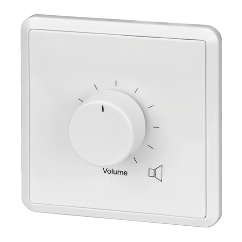
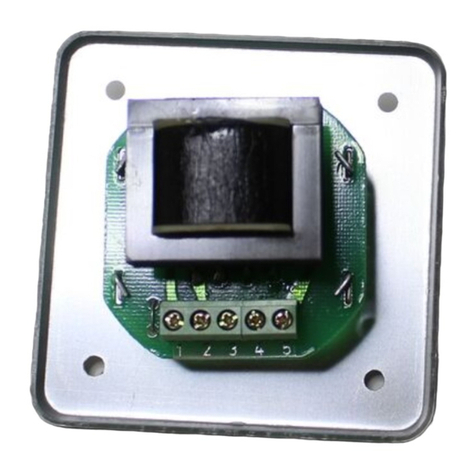
Monacor ATT-212/WS User manual

ELECTRONICS FOR SPECIALISTS ELECTRONICS FOR SPECIALISTS ELECTRONICS FOR SPECIALISTS ELECTRONICS FOR SPECIALISTS ELECTRONICS FOR SPECIALISTS ELECTRONICS
ATT-212/WS Bestell-Nr. •Order No. 17.3670
ATT-224/WS Bestell-Nr. •Order No. 17.3680
ATT-235/WS Bestell-Nr. •Order No. 17.0580
ATT-250/WS Bestell-Nr. •Order No. 17.0590
ATT-2100/WS Bestell-Nr. •Order No. 17.2610
MONACOR INTERNATIONAL GmbH & Co. KG • Zum Falsch 36 • 28307 Bremen • Germany
Copyright©by MONACOR INTERNATIONAL. All rights reserved. A-0865.99.07.05.2018
100V
CD
ATT-2 . . / WSAmp.
100 V Audio Line
10
0
4 OUT+
IN+ 1
Speaker 1 Speaker 2 Speaker …
IN
-
2 3 OUT
-
ATT-250/WS: max. 50 W
ATT-2100/WS: max. 100 W
ATT-212/WS: max. 12 W
ATT-224/WS: max. 24 W
ATT-235/WS: max. 35 W
Volume
100V
CD
ATT-2 . . / WSAmp.
100 V Audio Line
10
0
Speaker 1 Speaker 2 Speaker …
4 OUT+
IN+ 1
IN
-
2 3 OUT
-
ATT-250/WS: max. 50 W
ATT-2100/WS: max. 100 W
ATT-212/WS: max. 12 W
ATT-224/WS: max. 24 W
ATT-235/WS: max. 35 W
Volume
A1
+4
+
2
-
3
-
OUT
IN
➀
➁ ➂
Atténuateur Public Adress
Cette notice s’adresse aux installateurs possédant des
connaissances suffisantes en technique de sonorisation
ligne 100V. Veuillez lire la présente notice avec atten-
tion avant l‘installation et conservez-la pour pouvoir
vous y reporter ultérieurement.
1 Possibilités d’utilisation
L’atténuateur est spécialement conçu pour une utilisation
dans les systèmes de Public Adress avec technique ligne 100V.
La puissance nominale maximale par le haut-parleur suivant
ou le groupe de haut-parleurs suivants ne doit pas être dépas-
sée : voir caractéristiques techniques.
L’atténuateur doit être placé dans une prise encastrée ou
dans une prise en saillie (par exemple ATT-200 de MONACOR).
2 Conseils d’utilisation
L’appareil répond à toutes les directives nécessaires de l’Union
européenne et porte donc le symbole .
•
L’appareil n’est conçu que pour une utilisation en intérieur.
Protégez-le des éclaboussures, de tout type de projections
d’eau, de l’humidité élevée et de la chaleur (température
ambiante admissible 0–40°C).
•
Les câbles haut-parleurs sont sensibles aux interférences
électriques. Il convient de les placer à une distance de
quelques mètres des sources d’interférences (par exemple
dimmers, interrupteurs lumineux).
•
Pour le nettoyage, utilisez un chiffon sec et doux, en aucun
cas de produits chimiques ou d’eau.
•
Nous déclinons toute responsabilité en cas de dommages
corporels ou matériels résultants si l’appareil est utilisé dans
un but autre que celui pour lequel il a été conçu, s’il n’est
pas correctement branché ou s’il y a surcharge ; de même,
la garantie deviendrait caduque.
Lorsque l’appareil est définitivement retiré du
service, vous devez le déposer dans une usine de
recyclage de proximité pour contribuer à son élimi-
nation non polluante.
3 Branchement électrique
AVERTISSEMENT Pendant le fonctionnement, une tension de
100V au plus est présente aux bornes ! Seul
un technicien spécialisé est habilité à effec-
tuer l’installation.
Faites attention à l’adaptation correcte de la puissance. Une
surcharge peut endommager l‘amplificateur et l’atténuateur!
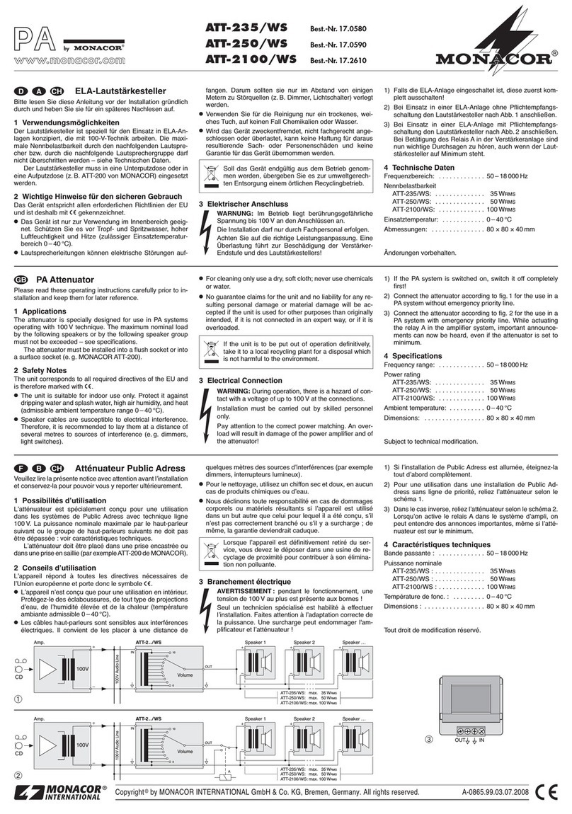
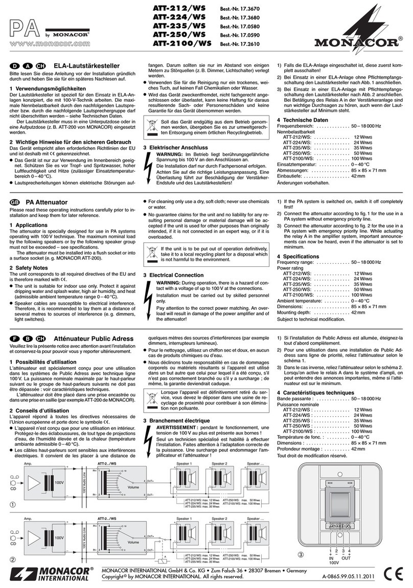
1) Si l’installation de Public Adress est allumée, éteignez-la
tout d’abord complètement.
2) Pour une utilisation dans une installation de Public
Address sans ligne de priorité, reli ez l’atténuateur selon
le schéma1.
3) Dans le cas inverse, reliez l’atténuateur selon le schéma2.
Lorsqu’on active le relais A dans le système d’ampli, on
peut entendre des annonces importantes, même si l’atté-
nuateur est sur le minimum.
4 Caractéristiques techniques
Bande passante : . . . . . . . . 50–18000 Hz
Puissance nominale
ATT-212/WS : . . . . . . . . . . 12 W
ATT-224/WS : . . . . . . . . . . 24 W
ATT-235/WS : . . . . . . . . . . 35 W
ATT-250/WS : . . . . . . . . . . 50 W
ATT-2100/WS : . . . . . . . . . 100W
Température de fonc. : . . . 0– 40 °C
Dimensions : . . . . . . . . . . . . 85 × 85 × 71mm
Profondeur montage : . . . . 42mm
Tout droit de modification réservé.
PA Attenuator
These instructions are intended for installers with suf-
ficient knowledge in 100V technology for PA appli-
cations. Please read the instructions carefully prior to
installation and keep them for later reference.
1 Applications
The attenuator is specially designed for use in PA systems
operating with 100V technology. The maximum nominal load
by the following speakers or by the following speaker group
must not be exceeded – see specifications.
The attenuator must be installed into a flush socket or
into a surface socket (e.g. MONACOR ATT-200).
2 Safety Notes
The unit corresponds to all relevant directives of the EU and
is therefore marked with .
•
The unit is suitable for indoor use only. Protect it against
dripping water and splash water, high air humidity, and
heat (admissible ambient temperature range 0–40°C).
•
Speaker cables are susceptible to electrical interference.
Therefore, it is recommended to lay them at a distance of
several metres to sources of interference (e.g. dimmers,
light switches).
•
For cleaning only use a dry, soft cloth; never use chemicals
or water.
•
No guarantee claims for the unit and no liability for any
resulting personal damage or material damage will be
accepted if the unit is used for other purposes than orig-
inally intended, if it is not connected in an expert way, or
if it is overloaded.
If the unit is to be put out of operation definitively,
take it to a local recycling plant for a disposal which
is not harmful to the environment.
3 Electrical Connection
WARNING During operation, there is a hazard of contact
with a voltage of up to 100V at the connec-
tions. Installation must be carried out by skilled
personnel only.
Pay attention to the correct power matching. An overload
will result in damage of the power amplifier and of the
attenuator!
1) If the PA system is switched on, switch it off completely
first!
2) Connect the attenuator according to fig.1 for the use in a
PA system without emergency priority line.
3) Connect the attenuator according to fig.2 for the use in a
PA system with emergency priority line. While actuating
the relay A in the amplifier system, important announce-
ments can now be heard, even if the attenuator is set to
minimum.
4 Specifications
Frequency range: . . . . . . . . 50– 18 000 Hz
Power rating
ATT-212/WS: . . . . . . . . . . 12 W
ATT-224/WS: . . . . . . . . . . 24 W
ATT-235/WS: . . . . . . . . . . 35 W
ATT-250/WS: . . . . . . . . . . 50 W
ATT-2100/WS: . . . . . . . . . 100W
Ambient temperature:. . . . 0 – 40 °C
Dimensions: . . . . . . . . . . . . 85 × 85 × 71mm
Mounting depth: . . . . . . . . 42 mm
Subject to technical modification.
ELA-Lautstärkesteller
Diese Anleitung richtet sich an Installateure, die aus-
reichende Fachkenntnisse in der 100-V-Beschallungs-
technik besitzen. Bitte lesen Sie die Anleitung vor der
Installation gründlich durch und heben Sie sie für ein
späteres Nachlesen auf.
1 Verwendungsmöglichkeiten
Der Lautstärkesteller ist speziell für den Einsatz in ELA-An-
lagen konzipiert, die mit 100-V-Technik arbeiten. Die maxi-
male Nennbelastbarkeit durch den nachfolgenden Lautspre-
cher bzw. durch die nachfolgende Lautsprechergruppe darf
nicht überschritten werden – siehe Technischen Daten.
Der Lautstärkesteller muss in eine Unterputzdose oder in
eine Aufputzdose (z.B. ATT-200 von MONACOR) eingesetzt
werden.
2 Wichtige Hinweise für den sicheren Gebrauch
Das Gerät entspricht allen relevanten Richtlinien der EU und
ist deshalb mit gekennzeichnet.
•
Das Gerät ist nur zur Verwendung im Innenbereich ge-
eignet. Schützen Sie es vor Tropf- und Spritzwasser, hoher
Luftfeuchtigkeit und Hitze (zulässiger Einsatztemperaturbe-
reich 0–40 °C).
•
Lautsprecherleitungen können elektrische Störungen auf-
fangen. Darum sollten sie nur im Abstand von einigen
Metern zu Störquellen (z.B. Dimmer, Lichtschalter) verlegt
werden.
•
Verwenden Sie für die Reinigung nur ein trockenes, weiches
Tuch, auf keinen Fall Chemikalien oder Wasser.
•
Wird das Gerät zweckentfremdet, nicht fachgerecht ange-
schlossen oder überlastet, kann keine Haftung für daraus re-
sultierende Sach- oder Personenschäden und keine Garantie
für das Gerät übernommen werden.
Soll das Gerät endgültig aus dem Betrieb genom-
men werden, übergeben Sie es zur umweltgerech-
ten Entsorgung einem örtlichen Recyclingbetrieb.
3 Elektrischer Anschluss
WARNUNG Im Betrieb liegt berührungsgefährliche Span-
nung bis 100V an den Anschlüssen an. Die Ins-
tallation darf nur durch Fachpersonal erfolgen.
Achten Sie auf die richtige Leistungsanpassung. Eine Über-
lastung führt zur Beschädigung der Verstärker-Endstufe
und des Lautstärkestellers!
1) Falls die ELA-Anlage eingeschaltet ist, diese zuerst kom-
plett ausschalten!
2) Bei Einsatz in einer ELA-Anlage ohne Pflichtempfangs-
schaltung den Lautstärkesteller nach Abb.1 anschließen.
3) Bei Einsatz in einer ELA-Anlage mit Pflichtempfangsschal-
tung den Lautstärkesteller nach Abb.2 anschließen. Bei
Betätigung des Relais A in der Verstärkeranlage sind nun
wichtige Durchsagen zu hören, auch wenn der Lautstärke-
steller auf Minimum steht.
4 Technische Daten
Frequenzbereich: . . . . . . . . 50– 18 000 Hz
Nennbelastbarkeit
ATT-212/WS: . . . . . . . . . . 12 W
ATT-224/WS: . . . . . . . . . . 24 W
ATT-235/WS: . . . . . . . . . . 35 W
ATT-250/WS: . . . . . . . . . . 50 W
ATT-2100/WS: . . . . . . . . . 100W
Einsatztemperatur:. . . . . . . 0– 40 °C
Abmessungen: . . . . . . . . . . 85 × 85 × 71mm
Einbautiefe: . . . . . . . . . . . . 42mm
Änderungen vorbehalten.
DeutschEnglishFrançais
CARTONS ET EMBALLAGE
PAPIER À TRIER
ELECTRONICS FOR SPECIALISTS ELECTRONICS FOR SPECIALISTS ELECTRONICS FOR SPECIALISTS ELECTRONICS FOR SPECIALISTS ELECTRONICS FOR SPECIALISTS ELECTRONICS
ATT-212/WS Bestell-Nr. •Order No. 17.3670
ATT-224/WS Bestell-Nr. •Order No. 17.3680
ATT-235/WS Bestell-Nr. •Order No. 17.0580
ATT-250/WS Bestell-Nr. •Order No. 17.0590
ATT-2100/WS Bestell-Nr. •Order No. 17.2610
MONACOR INTERNATIONAL GmbH & Co. KG • Zum Falsch 36 • 28307 Bremen • Germany
Copyright©by MONACOR INTERNATIONAL. All rights reserved. A-0865.99.07.05.2018
100V
CD
ATT-2 . . / WSAmp.
100 V Audio Line
10
0
4 OUT+
IN+ 1
Speaker 1 Speaker 2 Speaker …
IN
-
2 3 OUT
-
ATT-250/WS: max. 50 W
ATT-2100/WS: max. 100 W
ATT-212/WS: max. 12 W
ATT-224/WS: max. 24 W
ATT-235/WS: max. 35 W
Volume
100V
CD
ATT-2 . . / WSAmp.
100 V Audio Line
10
0
Speaker 1 Speaker 2 Speaker …
4 OUT+
IN+ 1
IN
-
2 3 OUT
-
ATT-250/WS: max. 50 W
ATT-2100/WS: max. 100 W
ATT-212/WS: max. 12 W
ATT-224/WS: max. 24 W
ATT-235/WS: max. 35 W
Volume
A1
+4
+
2
-
3
-
OUT
IN
➀
➁ ➂
Regulator głośności
Niniejsza instrukcja przeznaczona jest instalatorów
posiadających wiedzę w zakresie systemów PA pracują-
cych w technice 100V. Przed rozpoczęciem użytkowania
proszę zapoznać się z instrukcją, a następnie zachować
ją do wglądu.
1 Zastosowanie
Regulator został specjalnie zaprojektowany do użytku w sys-
temach radiowęzłowych 100V. Nie wolno obciążać go głośni-
kiem lub grupą głośników o mocy maksymalnej przekracza-
jącą dopuszczalną – zobaczyć specyfikację techniczną.
Regulator jest montowany w specjalnych puszkach pod
lub nadtynkowych (np. MONACOR ATT-200).
2 Środki bezpieczeństwa
Urządzenie spełnia wszystkie wymagania norm UE dzięki
temu został oznaczony symbolem .
•
Urządzenie to przeznaczone jest tylko do użytku wewnątrz
pomieszczeń. Należy chronić je przed wilgocią i wysoką tem-
peraturą (średnia temperatura otoczenia powinna zawierać
się w przedziale od 0 do 40°C).
•
Kable głośnikowe mogą być podatne na zakłócenia elek-
tryczne. Dlatego powinny one być poprowadzone w pewnej
odległości od źródeł zakłóceń (np. ściemniaczy, włączników
światła).
•
Do czyszczenia regulatorów należy używać tylko suchej
miękkiej szmatki. Nie wolno używać do tego celu wody lub
środków chemicznych.
•
Jeśli urządzenie jest wykorzystywane do innych celów niż
jego przeznaczenie, jeśli nie zostało podłączone przez kwali-
fikowany personel lub jeśli zostało przeciążone, firma MONA-
COR nie ponosi odpowiedzialności za możliwe uszkodzenia.
Aby nie zaśmiecać środowiska po całkowitym za-
kończeniu eksploatacji urządzenia należy je oddać
do punktu recyklingu.
3 Podłączenie
UWAGA W czasie pracy na przyłączu linii występuje
niebezpieczne napięcie osiągające do 100V.
Instalacja regulatora może być tylko wyko-
nana przez wykwalifikowany personel.
Szczególną uwagę należy zwrócić na odpowiedni dobór
mocy. Przesterowanie może doprowadzić do uszkodzenia
wzmacniacza oraz/lub regulatora!
1) Przed podłączeniem regulatora należy bezwzględnie
wyłączyć system audio!
2) Podłączyć regulator zgodnie z rys.1 w przypadku pracy w
systemie PA bez obwodu priorytetu.
3) Podłączyć regulator zgodnie z rys.2 w przypadku pracy w
systemie PA z obwodem priorytetu. Po zwarciu przekaź-
nika A we wzmacniaczu, komunikaty alarmowe będą sły-
szane nawet gdy regulator został skręcony na mimnimum.
4 Dane techniczne
Pasmo przenoszenia: . . . . . 50– 18 000 Hz
Maksymalne obciążenie
ATT-212/WS: . . . . . . . . . . 12 W
ATT-224/WS: . . . . . . . . . . 24 W
ATT-235/WS: . . . . . . . . . . 35 W
ATT-250/WS: . . . . . . . . . . 50 W
ATT-2100/WS: . . . . . . . . . 100W
Temperatura pracy: . . . . . . 0– 40 °C
Wymiary:. . . . . . . . . . . . . . . 85 × 85 × 71mm
Głębokość montażowa: . . . 42mm
Z zastrzeżeniem do możliwych zmian.
Atenuador de sonorización PA
Estas instrucciones van dirigidas a instaladores con un
conocimiento suficiente sobre la tecnología de 100V
en aplicaciones para megafonía. Lea atentamente estas
instrucciones antes de la instalación y guárdelas para
usos posteriores.
1 Aplicaciones
El atenuador está especialmente diseñado para ser utili-
zado en sistemas PA que trabajan con técnología de 100V.
La carga nominal máxima por los altavoces que le siguen o
por el grupo de altavoces que sigue no debe excederse – ver
especificaciones.
El atenuador debe instalarse en una toma empotrada o de
superficie (p.ej. MONACOR ATT-200).
2 Notas de seguridad
El aparato cumple con todas las directivas relevantes por la UE
y por lo tanto está marcado con el símbolo .
•
Este aparato está concebido solamente para una utilización
en interiores. Protegerlo de todo tipo de proyecciones de
agua, de salpicaduras, de la humedad del aire elevada y del
calor (temperatura admisible ambiente 0–40ºC).
•
Los cables de altavoces son susceptibles a interferencias eléc-
tricas. Por eso deberían colocarse solamente a una distancia
de algunos metros de fuentes de interferencia (p.ej. dim-
mer, interruptor de luz).
•
Para limpiarlo, utilizar un trapo seco y blando, en ningún
caso, productos químicos o agua.
•
Declinamos cualquier responsabilidad en caso de daños ma-
teriales o corporales resultandos si el aparato se utiliza por
cualquier otro fin que no sea el adecuado, no se conecta de
manera experta o en caso de sobrecargas.
Una vez el aparato es retirado definitivamente del
servicio, debe depositarse en una fábrica de reciclaje
adaptada para su eliminación no contaminante.
3 Conexión eléctrica
ADVERTENCIA Durante la operación, hay voltaje de con-
tacto peligroso hasta 100V en las conexio-
nes. La instalación debe llevarse solamente
por personal especializado.
Poner atención a la adaptación correcta de la potencia. ¡Una
sobrecarga puede causar daños en el amplificador y en el
atenuador!
1) ¡Si el sistema PA está conectado, primero apagarlo com-
pletamente!
2) Conectar el atenuador como en la fig.1 para usarlo en un
sistema PA sin línea de emergencia prioritaria.
3) Conectar el atenuador como en la fig.2 para usarlo en un
sistema PA con línea de emergencia prioritaria. Cuando el
relé A del sistema amplificador está activo, ahora pueden
escuchar anunciaciones importantes, aun cuando el ate-
nuador está al mínimo.
4 Especificaciones
Rango frecuencias:. . . . . . . 50 –18000Hz
Capacidad nominal
ATT-212/WS: . . . . . . . . . . 12 W
ATT-224/WS: . . . . . . . . . . 24 W
ATT-235/WS: . . . . . . . . . . 35 W
ATT-250/WS: . . . . . . . . . . 50 W
ATT-2100/WS: . . . . . . . . . 100W
Temperatura ambiente: . . . 0–40 °C
Dimensiones: . . . . . . . . . . . 85 × 85 × 71mm
Profundidad montaje: . . . . 42mm
Sujeto a modificaciones técnicas.
Attenuatore PA
Queste istruzioni sono rivolte agli installatori che pos-
siedono delle conoscenze specifiche sufficienti della tec-
nica di sonorizzazione a 100V. Vi preghiamo di leggerle
attentamente prima dell‘installazione e di conservarle
per un uso futuro.
1 Possibilità d’impiego
L’attenuatore è stato realizzato specialmente per l’impiego in
impianti PA che lavorano con uscita audio 100V. Non si deve
superare la potenza nominale massima con l’altoparlante o il
gruppo di altoparlanti a valle – vedi di dati tecnici.
L’attenuatore deve essere montato in una scatola da
incasso oppure in una a muro (p.es. ATT-200 di MONACOR).
2 Avvertenze di sicurezza
Quest’apparecchio è conforme a tutte le direttive rilevanti
dell’UE e pertanto porta la sigla .
•
Lo strumento è previsto solo per l’uso all’interno di locali.
Proteggerlo dall’acqua gocciolante e dagli spruzzi d’acqua,
da alta umidità dell’aria e dal calore (temperatura d’im-
piego ammessa fra 0 e 40°C).
•
I cavi per altoparlanti possono captare dei disturbi elettrici.
Perciò è opportuno sistemarli a distanza di alcuni metri da
fonti di disturbi (p.es. dimmer, interruttori della luce).
•
Per la pulizia usare solo un panno morbido, asciutto; non
impiegare in nessun caso prodotti chimici o acqua.
•
Nel caso d’uso improprio, di collegamenti sbagliati o di
sovraccarico dell’apparecchio, non si assume nessuna re-
sponsabilità per eventuali danni consequenziali a persone
o a cose e non si assume nessuna garanzia per lo strumento.
Se si desidera eliminare l’apparecchio definitiva-
mente, consegnarlo per lo smaltimento ad un’isti-
tuzione locale per il riciclaggio.
3 Collegamento elettrico
AVVERTIMENTO Durante il funzionamento, ai contatti è pre-
sente una tensione pericolosa fino a 100V.
L’installazione deve essere fatta solo da per-
sonale qualificato.
Fare attenzione al corretto adattamento della potenza. Il
sovraccarico provoca il danneggiamento dello stadio finale
dell’amplificatore e dell’attenuatore!
1) Se l’impianto PA è acceso, spegnerlo prima completa-
mente!
2) Nel caso di uso in un impianto PA senza linea prioritaria di
emergenza, collegare l’altoparlante come da fig.1.
3) Nel caso di uso in un impianto PA con linea prioritaria
di emergenza, collegare l’altoparlante come da fig.2. Se
viene attivato il relè A nell’impianto di amplificazione, si
sentono gli avvisi importanti, anche se il regolatore è sul
minimo.
4 Dati tecnici
Gamma di frequenze: . . . . 50–18 000 Hz
Potenza nominale
ATT-212/WS: . . . . . . . . . . 12 W
ATT-224/WS: . . . . . . . . . . 24 W
ATT-235/WS: . . . . . . . . . . 35 W
ATT-250/WS: . . . . . . . . . . 50 W
ATT-2100/WS: . . . . . . . . . 100W
Temperatura d’esercizio: . . 0 – 40°C
Dimensioni:. . . . . . . . . . . . . 85 × 85 × 71mm
Profondità di montaggio: . 42 mm
Con riserva di modifiche tecniche.
ItalianoEspañolPolski

This manual suits for next models

14

Other Monacor Control Unit manuals

Monacor SAM-2 User manual

Monacor

Monacor SAM-2 User manual

Monacor PA-1120DMT User manual

Monacor

Monacor PA-1120DMT User manual

Monacor ATT-212H/WS User manual

Monacor

Monacor ATT-212H/WS User manual

Monacor ATT-306PEU User manual

Monacor

Monacor ATT-306PEU User manual

Monacor PMA-102 User manual

Monacor

Monacor PMA-102 User manual

Monacor ATT-442ST User manual

Monacor

Monacor ATT-442ST User manual

Monacor ATT-210/WS User manual

Monacor

Monacor ATT-210/WS User manual

Monacor ATT-1950 User manual

Monacor

Monacor ATT-1950 User manual

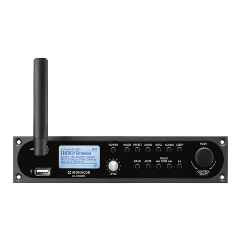
Monacor PA-1200IRD User manual

Monacor

Monacor PA-1200IRD User manual

Monacor PA-1120DMT User manual

Monacor

Monacor PA-1120DMT User manual

Monacor ATT-412PEU User manual

Monacor

Monacor ATT-412PEU User manual

Monacor PA-1200EX User manual

Monacor

Monacor PA-1200EX User manual

Monacor img Stage Line TXS-820M User manual

Monacor

Monacor img Stage Line TXS-820M User manual

Monacor ATT-110/SI User manual

Monacor

Monacor ATT-110/SI User manual

Monacor img Stage Line TXS-820M User manual

Monacor

Monacor img Stage Line TXS-820M User manual

Monacor ATT-312PEU User manual

Monacor

Monacor ATT-312PEU User manual

Monacor 0171430 User manual

Monacor

Monacor 0171430 User manual

Monacor MPA-1 User manual

Monacor

Monacor MPA-1 User manual

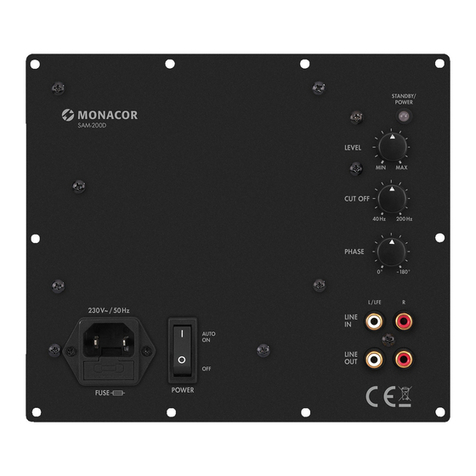
Monacor SAM-200D User manual

Monacor

Monacor SAM-200D User manual

Monacor ATT-135/SI User manual

Monacor

Monacor ATT-135/SI User manual

Monacor IPA-25D User manual

Monacor

Monacor IPA-25D User manual

Monacor TXA-802MBT User manual

Monacor

Monacor TXA-802MBT User manual

Monacor PA ATT-325ST User manual

Monacor

Monacor PA ATT-325ST User manual

Monacor DMP-100R User manual

Monacor

Monacor DMP-100R User manual

Popular Control Unit manuals by other brands

Comunello CU 230V HP Installation and user manual

Comunello

Comunello CU 230V HP Installation and user manual

Honeywell Notifier XP6-R Installation and maintenance instructions

Honeywell

Honeywell Notifier XP6-R Installation and maintenance instructions

iSMA CONTROLLI SfAR-S-8AI2DO user manual

iSMA CONTROLLI

iSMA CONTROLLI SfAR-S-8AI2DO user manual

Fermator ECC+ 230 V user manual

Fermator

Fermator ECC+ 230 V user manual

aci PIM CPN user manual

aci

aci PIM CPN user manual

GEA SVA 455 Series operating instructions

GEA

GEA SVA 455 Series operating instructions

Tektronix 7B70 instruction manual

Tektronix

Tektronix 7B70 instruction manual

Satel GSM LT-1S user manual

Satel

Satel GSM LT-1S user manual

WAGO WAGO-TO-PASS 761 manual

WAGO

WAGO WAGO-TO-PASS 761 manual

Huawei ME936 Hardware guide

Huawei

Huawei ME936 Hardware guide

Panasonic CF-BAJ0256U operating instructions

Panasonic

Panasonic CF-BAJ0256U operating instructions

SMA MD.SEN-40 installation manual

SMA

SMA MD.SEN-40 installation manual

GBD AS07200 Instructions for installation

GBD

GBD AS07200 Instructions for installation

Siemens ValvePAC Series Installation instruction

Siemens

Siemens ValvePAC Series Installation instruction

Mallory HYFIRE V installation instructions

Mallory

Mallory HYFIRE V installation instructions

Baxi Boiler control panel Quick reference guide

Baxi

Baxi Boiler control panel Quick reference guide

TPA TRS67-8I-8O Documentation

TPA

TPA TRS67-8I-8O Documentation

tau DC20 installation guide

tau

tau DC20 installation guide

manuals.online logo
manuals.online logoBrands
  • About & Mission
  • Contact us
  • Privacy Policy
  • Terms and Conditions

Copyright 2025 Manuals.Online. All Rights Reserved.