Dolphin Charger PROLITE Series User manual

12V15A
115V : Code 399715
230V : Code 399710
12V25A
115V : Code 399725
230V : Code 399720
Automatic IP65 battery chargers
OPERATING
& USERS MANUAL
PROLITE Series

WARNING
This manual contains vital and essential information,
in order to avoid electrical shocks, overcharging
or irreversible damage to the material. The owner
should read and understand this document before
operating the charger.
This device is not intended for use by persons
(including children) with physical, sensory or mental
disability, or by persons lacking experience or
knowledge, unless they have received from a person
in charge of their safety adequate supervision or
preliminary instructions on how to use the device.
For any question, contact your dealer.
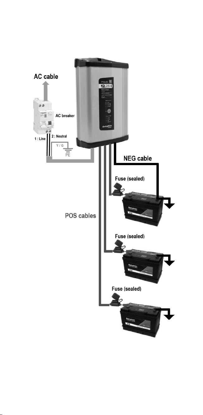
Installation
This charger is suitable for use in marine engine
compartments, and near fuel tanks.
Do not install the charger near a heat source.
It should not be installed in an airtight or badly
ventilated area.
Leave at least 10cm / 3inches clearance around the
charger for proper ventilation.
Install the charger in a vertical position to create
an optimal ventilation. Note that wirings are at the
bottom of the charger.
All electrical connections to and from the charger
must remain accessible all the time.
In order to maintain watertightness, it is strictly
forbidden to dismantle the charger and/or to modify
the casing and/or wirings in any way.
The charger must be correctly and strongly fixed.
This device is not a toy and must be kept out of the
reach of children.

Connections
According to the model, the charger is set to be
connected to a monophase network 230V 50Hz or
115V 60Hz (refer with technical specifications).
The installation to which the charger is connected
must comply with the standards currently enforced in
the country of use.
In order to protect the occupants, the main power
supply access must be attached to a dierential
circuit breaker (refer with technical specifications).
For safety reason, the green / yellow wire of the
power cord must strictly be connected to the earth of
the installation.
The cable N°1 of power cord must be connected to
the LINE or PHASE, the N°2 to the NEUTRAL.
To prevent overheating, ensure the correct tightening
of the connections.
Each access connected to the battery is protected
with a sealed fuse integrated with the wire. Do not
remove or change those fuses.
Output batteries must be connected to the charger
before its power-on.
This device complies with enforced standards
regarding emitted interferences and disturbances of
external origin.
Regarding electromagnetic interferences, ensure that
other materials used are compatible with this device
in order to avoid irreversible damage.
WARNING

Serial number
The S/N is available on the grey sticker on the top
side of the charger.
Choosing the charging curve
It is important to choose the correct charging curve,
appropriate with the battery technology. An incorrect
choice can cause irreversible damage.
In particular, risk of overheating and noxious gases
in case of overvoltage to the battery.
The LITHIUM cycle charge is only compatible with
LiFePo4 batteries with integrated BMS (Battery
Management System).
Please consult the battery manufacturer’s
recommendation.
Maintenance
If necessary, fuses on positive access must be
replaced with identical products.
This charger cannot be dismantled and thus, the
electronic power board is inaccessible. Except fuses,
therefore, any maintenance on site is prohibited.
WARNING

CONNECTIONS

TECHNICAL SPECIFICATIONS
12V/15A 12V/25A
Input
Voltage 115V or 230V (+/-10%)
According to model 115/230V (+/-10%)
Frequency 50/60 hz (+/-10%)
Cos phi > 0,5 > 0,9
Eciency > 90%
Max Current 4A or 2A
According to model 4A/2A
Output
Qty of output 2 3
Qty of cycles charge 4 (3 stages I.Uo.U)
Boost / Float
Open Lead
AGM – Gel
Lead Calcium
Lithium
14,5V / 13,4V
14,5V / 13,6V
15,0V / 13,8V
14,5V
Voltage precision +/-2%
Max Power / Current 180W / 15A 300W / 25A
Ripple < 1% (BW < 20MHz)
Protections
Electronic Output short circuit / Output over voltage
Output reverse polarity / Over temperature
Internal fuses General protection (irreversible damage)
External +BAT fuses F20A F30A
General
Display Front tri-color LED
Control Front push-button or via “Dolphin Connect App”
Operating t° -10°C to +55°C (automatic derating)
Storage t° -20°C to +70°C
Humidity 10% to 90%
IP IP65
Ventilation Natural convection
Safety EN60335-1, EN60335-2-29, ISO8846,
SAEJ1171, UL1236

TECHNICAL SPECIFICATIONS
12V/15A 12V/25A
EMC EN 55014-1, EN55014-2
Casing Anodized extruded aluminium
Mounting Wall-mounting 2 x M4 Screws
Dimensions 142 x 72 x 194 mm
5.51 x 2.76 x 7.68’’
140 x 70 x 245 mm
5.51 x 2.76 x 9.65’’
Weight 1,4 Kg / 3.1 lbs 1,7 Kg / 3.8 lbs
Wires length 1,8 m / 6 feet
AC access 3 x 0,75mm² stripped cable
With NEMA 15-5 plug for 115V models
DC access AWG12 or 14 (according to model)
with M8 ring terminals

OPERATING INSTRUCTIONS
Select the cycle charge
1. Power-on the charger connected to the batteries.
2. Note that during the power-on of the charger, the
LED indicates for a few seconds the current cycle
charge (refer to below color vs cycle).
3. Wait a few seconds and verify that the charger is
correctly charging the batteries (NORMAL mode).
4. Press the push-button for 3 sec.
5. The charger enters the SETTING mode, and the
LED is blinking.
6. Do not wait, and with the push-button, select the
color of the LED, so the type of battery.
Led Battery type
Green Open Lead
Yellow AGM - Gel
Red Lead Calcium
Green / red Lithium
7. After your choice, wait a few seconds, the
charger returns automatically in NORMAL mode.
8. Preventively, verify the output charge voltage
(Boost & Float phases).

OPERATING INSTRUCTIONS
Front display
Mode LED Status
ABS mode Yellow Batteries are charging.
Time required to complete
“Absorption” depends on the
initial SOC of the batteries,
but it is limited to 8hrs
EQUAL mode Yellow blinking Batteries are coming to the
end of the cycle charge.
Time required to complete
“Equalization” depends on
the initial SOC of the batteries
and varies between 30mn
to 4hrs
End of EQUAL mode Green blinking Batteries are almost charged.
Floating mode will begin in
less than 30mn
FLOAT mode Green Batteries are completely
charged
OT default
(Over Temperature)
Red
slow blinking
Charger is stopped for a
period of 30sec min. The
restart is automatic once the
defect has disappeared.
>> Check the external ambient
temperature.
RP default
(Reverse Polarity)
Green / red
blinking
Connection error on batteries
side or internal battery fuse
broken. The restart is manual
after a power o / power
on, once the defect has
disappeared.
>> Check all connections and
the polarity of the batteries.
>> Note that the internal
battery fuse cannot be
replaced.
OVO default
(Output Over Voltage)
Red
fast blinking
Charger is stopped for a
period of 30sec. The restart is
automatic once the defect has
disappeared.
>> Check the output voltage.
In general, this default is
irreversible.

OPERATING INSTRUCTIONS
Dolphin Connect App

DIMENSIONS
ProLite 12V15A

DIMENSIONS
ProLite 12V25A

WARRANTY
In order to prevent all risks due to the incorrect
use of the device, please read carefully the list of
possible situations or faults not covered by the
warranty.
Disassembly and/or modification of the casing
resulting into the loss of the watertightness and/or the
damage of the charger.
Disassembly and/or modification of the electronic
power board resulting into the malfunction or the
damage of the charger.
Mechanical shocks on the casing resulting into the
loss of the watertightness and/or the damage of the
charger.
Use of a non-appropriate main power supply (for
example a generator with a too high voltage) resulting
into the malfunction or the damage of the charger.
Over-voltage from the main or a lightning strike.
Battery in reverse polarity but connected “in live” to
a charger in operation, resulting into a damage of the
charger.
Obvious connections errors resulting into the
malfunction or the damage of the charger.
Wires modified, fuses removed or replaced with non-
appropriate products.
Water to the interior of the device resulting the
malfunction or the damage of the charger.
Cycle charge non appropriate with the technology of
the battery, in particular when the charge voltage is
too high, risk of overheating and noxious gases.
Use with LITHIUM batteries without integrated BMS.

contact@dolphin-charger.com
www.dolphin-charger.com
WARRANTY
Disposal
This device contains electronic and mechanical
components that must be recycled once the device is
obsolete.
All electronic devices must be returned to a local
distributor or to a specialized company for an
environmentally friendly disposal.
CE conformity
This product conforms to current European standards
and has a CE mark. Please contact us for the
certificate of conformity.
Photos are not contractual. © All rights reserved by Dolphin charger and Cats Power Design. Last update: October 2019
This manual suits for next models
6
Table of contents
Other Dolphin Charger Batteries Charger manuals