Dolphin 12V25A User manual

TECHNICAL MANUAL
12V25A
Code : 399121
12V40A
Code : 399123
EN
Power unit
DC & AC

NOT_AIO.PREMIUM-01 NOT_AIO.PREMIUM-01
SAFETY PRECAUTIONS
TO PREVENT ANY RISK OF ELECTRIC SHOCK
OR FIRE, READ THIS MANUAL CAREFULLY
BEFORE INSTALLING THE EQUIPMENT.
In the event of a problem, or something you do
not understand, contact KREPEL.
This unit is not designed to be used by children,
or persons with a physical, sensorial or mental
disability, or with insufcient experience or
knowledge, unless a safety supervisor is present or
they have received preliminary training in the use
of the unit.
Children should be supervised to avoid their
playing with the unit.
This unit contains components that may cause
electric arcs or sparks, when connecting cables
for example.
To prevent any risk of re or explosion, do not install
this unit close to inammable materials, liquids or
gases.
Installation precautions
In order to prevent any risk of overheating
or permanent damage to the unit, the
recommendations below should be strictly
followed.
4This unit should not be installed close to a heat
source.
4It should not be installed in a sealed or poorly
ventilated volume.
4The cooling vents must not be obstructed.
Leave an unobstructed space of at least 10cm
around the unit, to allow proper convection.
4The unit must not be exposed to run-off water,
water spray or any type of dust.
4It is strongly recommended that the unit be
mounted vertically, with the cable exit at the
bottom.
4The mains power socket and the battery
connector must remain accessible and workable
when the unit is installed.
4The case must not be structurally modied, for
example by drilling additional holes.
4This unit is not a toy, and should therefore
obviously not be left in the hands of a child.
Connection precautions
In order to prevent any risk of electric shock
or permanent damage to the unit, the
recommendations below should be strictly
followed.
The unit is designed to be connected to single
phase systems 230V or 115V, 50Hz or 60Hz.
The equipment supplied by this unit must be
compliant with the applicable regulations.
The power line must feature a cut-off device
with differential protection to protect individuals
against electric shock.
Refer to the unit electrical consumption data for
the selection and rating of the protection circuit-
breaker.
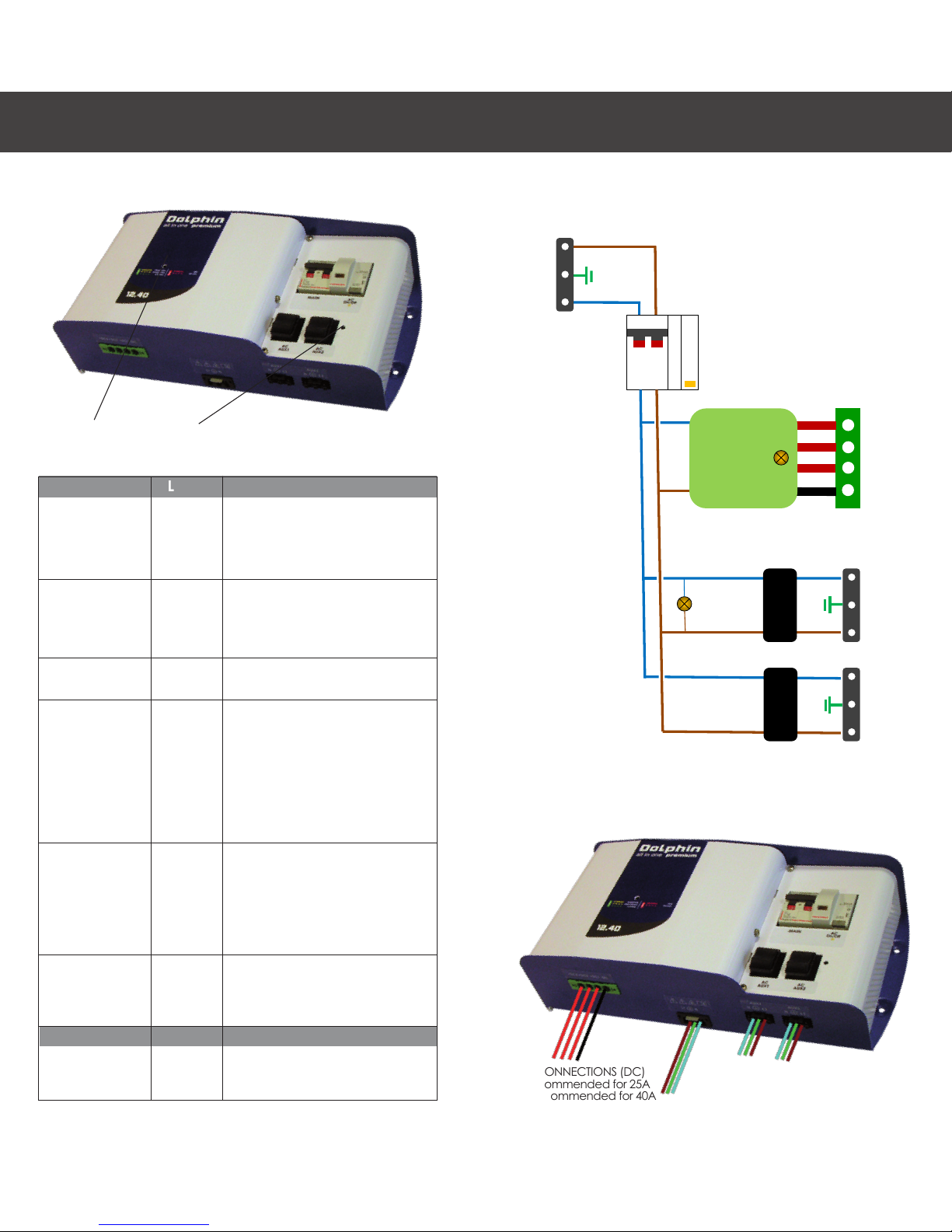
For safety reasons, the unit PE terminal must be
connected to the main earth of the installation
(green / yellow wire of mains power cable).
Refer to the wiring diagram for more information.
In order to prevent overheating, ensure that
cables are of the correct cross-section and that
the connections are tight.
EN

NOT_AIO.PREMIUM-01
NOT_AIO.PREMIUM-01
Mains power cable length must not exceed 3
metres, and 1.5 metres for the battery cables.
Ensure that the AC and DC cables are properly
connected, using the connector locks supplied
with each unit.
The protective covers supplied must be tted onto
the AC cables, rstly for protection against electric
shock and secondly the cables are mechanically
supported by the connector locks.
Precautions before operation
In order to prevent any risk of electric shock when
switching on or during operation, the following
directives should be strictly applied.
Obviously, the unit should not be disassembled
and the case (which is re-resistant) must be
properly assembled.
This unit is compliant with applicable regulations
concerning emitted interference and immunity
from external interference (see EMC section in
the Technical Specications).
During operation, be particularly careful to avoid
exposing the unit to conducted or radiated
interference exceeding the legal levels (e.g. unit
too close to a power radio-electrical transmitter).
Such exposure can cause serious malfunctions.
Furthermore, this unit emits conducted and
radiated interference at levels within the
applicable regulatory limits.
Ensure that other equipment used in the vicinity
is electro-magnetically compatible with this unit,
otherwise malfunctions may occur.
Unit serial No.
The unit serial number is on the grey label, bonded
to one of the case side panels.
The number is vertical and starts with a numerical
value indicating the year of manufacture (e.g.
14 for 2014), followed by a letter indicating the
month of manufacture (e.g.
C for the month of March) and a 4 or 5-digit
representing the unit number within the series.
The term Rev XX indicates the unit change or
evolution status.
Important: Note concerning the charging rate.
Using a charging cycle that is unsuitable for the
battery technology may seriously damage the
battery.
This is particularly the case when using a
charging voltage signicantly greater than that
recommended by the battery manufacturer.
A considerable risk of battery overheating, with
a release of noxious gases that can damage
health.
Refer to the manufacturer’s recommendations to
determine the correct charging cycle.
Maintenance precautions.
4In order to prevent any risk of electric shock
during outdoor maintenance work, the following
recommendations should be strictly applied.
4Maintenance operations should only be carried out by
a qualied technician.
SAFETY PRECAUTIONS EN

NOT_AIO.PREMIUM-01
NOT_AIO.PREMIUM-01
TECHNICAL SPECIFICATIONSSAFETY PRECAUTIONS EN
Free electrolyte
scanning charge
Boost = 14,4V
Float = 13,2V
Sealed lead-acid
scanning charge
Boost = 14,2V
Float = 13,6V
Lead-calcium
scanning charge
Boost = 14,8V
Float = 13,8V
Delphi
scanning charge
Boost = 15,4V
Float = 13,8V
Spiral cell agm Boost.1 = 14,8V
Boost.2 = 15,5V
Float = 13,8V
Winterizing Boost = 14,4V
Weekly automatic
Float = 13,2V
Gel
scanning charge
Boost = 14,4V
Float = 13,8V
Power supply Float = 13,6V
AC auxiliary output characteristics
Number of outputs 2
Voltage Same as mains power voltage
Frequency Same as mains power frequency
Max. current 10A
Protection 10A magnetic thermal circuit breaker
General
Operating T° -10°C to +55°C
Storage T° -20°C to +70°C
Relative humidity Max. 90% (without condensation)
Convection Forced (thermostat-controlled fan)
Standards EN61000-6-1, EN61000-6-3, EN60335
Case Wall-mounted in painted aluminium alloy
Mounting By 3 screws (diameter 4 mm)
Dimensions (mm) 395 x 188 x 103 mm
Weight < 3 kg
Mains power connector Type WINSTA (WAGO), 2 x 2,5 mm2
AC output connector Type WINSTA (WAGO), 2 x 2,5 mm2
Battery connector Type PC6/4 (Phoenix Contact), 4x16 mm2
4In the event of damage to the AC or DC cables, these
latter should only be replaced by authorised personnel, in
order to avoid danger.
4Mains power and batteries must be disconnected
(cable, connectors and/or main switches).
4Wait 5 min. before starting work on the case to allow
the high voltage capacitors to discharge.
4Battery fuses should only be replaced by fuses of
identical specication and ratings.
Code 399121 399123
Mains power characteristics
Voltage 230V +/- 10%
Frequency 50 - 60Hz +/- 10%
Charger
consumption 2,5A 4,0A
Auxiliaries
consumption Max. 10A total for both outputs
Display LED on front panel (yellow)
Differential circuit
breaker 16A 30mA
Charger fuse T6,3A T10A
Display On/Off LED on front panel (yellow)
Battery charger characteristics
Voltage 85V - 265V
Frequency 50 - 60Hz +/- 10%
Number of outputs 3 isolated outputs
Charging rates Total 8
Charge selector Toggle switch inside case
12V25A 12V40A
Voltage tolerance +/- 2%
Ripple < 1%
Max. current 25A +/- 5% 40A +/- 5%
-DC fuse F30A 2 x F30A
Protection By fuse, in the event of internal overhea-
ting, abnormal output voltage, output
short-circuit or reverse polarity
Display
3-colour LED on front panel
Yellow: Boost mode
Green: Float mode
Red: Fault

NOT_AIO.PREMIUM-01
NOT_AIO.PREMIUM-01
OPERATING MODES
MODE
Charging
Balancing
Floating
Internal
temperature
fault «Temp»
Abnormal
output voltage
fault «Volt out»
Battery fuse
fault «Bat fuse»
MODE
AC
On/Off
LED.1
Yellow
steady
Yellow
ashing
Green
ashing
Red
ashing
Red
steady
Rouge xe
LED.2
Yellow
steady
STATUS
Batteries are being charged.
Charging phase time varies up to 6
hours, depending on the battery’s
initial charge level.
End of battery charging phase.
Balancing phase time varies
between 30 minutes and 4 hours,
depending on the battery’s initial
charge status.
Batteries are charged.
Charger is in standby for a period
between 30 seconds and 10
minutes.
Restarting is automatic when the
fault is cleared.
4Check climatic conditions,
internal fan operating properly,
charger space volume.
Charger is in standby for a period
of 30 seconds.
Restarting is automatic when the
fault is cleared.
4The electronics board is probably
permanently defective.
Battery fuse is defective.
4Check connections, polarity
and battery charge status.
STATUS
Electricity cabinet power on
CONNECTIONS
BATTERY CONNECTIONS (DC)
6mm2 recommended for 25A
10mm2 recommended for 40A
EN
LED1 LED2
AC CONNECTIONS
3 x 2.5 mm2 recommended
N
PE
L1
PE
PE
N
N
L1
L1
I
0
I
0
-DC
+DC1
+DC2
+DC3
AC/DC
Battery
charger
Main
connector
Battery
connector
AUX1
connector
AUX2
connector
AUX1
breaker
AUX2
breaker
Main
breaker
AC
on/off
Circuit diagram
Connections

NOT_AIO.PREMIUM-01
NOT_AIO.PREMIUM-01
CONNECTIONS
Assembly of Winsta AC connectors
7 STEP 1
Strip the cable over around 3 cm
Strip the 3 wires over around 8 mm
Tin the bare copper ends
7 STEP 2
Remove the cap from the case, using a cutter
7 STEP 3
Thread the cable into the case
7 STEP 4
Insert a at screwdriver into the square hole, to open the
contact, and insert the wire. Repeat this operation on
the 3 wires, as shown in the wiring diagram
7 STEP 5
Insert the connector into the case and check that the
cable penetrates around 1 cm into the case.
7 STEP 6
Press on the sides of the case and t the
assembly screw
EN
DIMENSIONS
Installation dimensions
[
3RUWHGXJUDQG/\RQ
0,5,%(/&('(;
PGSFRQWDFW#PGSPRWRUFRP
7HO
)D[
3/$11
'X0RWHXUDX0RXYHPHQW
$
02',),&$7,216
'$7(6
,QG
&RGHV$UWLFOHV
23(
3URSULpWp0'3QHSHXWrWUHUHSURGXLWVDQVXQHDXWRULVDWLRQH[SUHVVHHWpFULWH
&RQWU{OH4XDOLWp
,QVWUXFWLRQVSDUWLFXOLqUHV
7ROpUDQFHV*pQpUDOHV
0DWLqUH
6<0
&UpDWLRQ
&RQIRUPH5R+6
GLPHQVLRQV
DQJOHV
pWDWVGHVXUIDFH
$OO,Q2QH3UHPLXP
0(&
LQG
'pVLJQDWLRQ
+RUV,QGLFHV
Charge
selector
Battery
fuses

NOT_AIO.PREMIUM-01
NOT_AIO.PREMIUM-01
WARRANTY
IN ORDER TO ENSURE THAT THE UNIT IS PROPERLY
USED, CAREFULLY READ THE LIST OF INCIDENTS
OR POTENTIAL DEFECTS NOT COVERED BY THE
WARRANTY
4Dropping the unpackaged unit can
permanently distort the case, and/or cause
the failure of the internal cooling fan or certain
electronic components.
4Modications to the case (particularly drilling
additional holes) can leave swarf or metal lings
on the electronics board, causing malfunctions or
permanent damage to the unit.
4Work or modications on the electronics board
can result in operating modes for which the unit
was not designed, causing permanent damage
to the unit.
4Connecting the unit to a power supply outside
tolerances (generally an excessive mains power
voltage) can cause permanent damage to the
unit.
4Accidental mains power overvoltage or a
lightning strike generally causes permanent
damage to the unit.
4Replacing battery fuses by fuses with different
ratings can cause permanent damage to the
unit.
4Obvious connection errors causing permanent
damage to the unit.
4Water spray or run-off water inside the unit can
cause permanent electronic malfunctions.
Important: Note concerning the charging rate.
Using a charging cycle that is unsuitable for the
battery technology may seriously damage the
battery.
This is particularly the case when using a
charging voltage signicantly greater than that
recommended by the battery manufacturer.
A considerable risk of battery overheating, with
a release of noxious gases that can damage
health.
Refer to the manufacturer’s recommendations to
determine the correct charging cycle.
Precautions for scrapping
This unit contains electronic components and
materials that must be recycled at the end of the
unit’s life cycle, for environmental reasons.
At the end of their life cycle, all units should be
either returned to the local distributor or entrusted
to a specialist electronic equipment recycling
company.
WARRANTY EN

NOT_AIO.PREMIUM-01
NOT_AIO.PREMIUM-01
Guarantee policy
Our complete two-year product warranty consists
of the following provisions:
4Dolphin guarantees the operation of its
products under normal use (when used within the
relevant specications) for a period of two years
after purchase from the DOLPHIN dealer with
a maximum period of three years after date of
production (see indication on product label)
4This warranty covers the costs of repairs and/
or replacement of the defective parts. Any costs
related to (dis)assembly, shipping, and/or travel
and lodging expenses for technicians are not
included.
4These warranties are void in situations in which
damage was caused due to use of Dolphint
products in circumstances for which they were not
intended, incorrect installation or maintenance,
replacement or modications carried out by
parties other than Dolphin certied support points
or damage caused by (sea) water, including (sea)
water entering an engine (however caused).
Returns for repairs or replacement
under our warranty
We advise you to have all returns coordinated by
your nearest local DOLPHIN distributor, dealer or
closest local representative ofce, unless you have
an express agreement with the headquarters in
France stating otherwise. All returns are subject to
the following conditions:
4An RMA (Return Materials Authorization)
registration number is necessary for all returns. This
number has to be specied on all packages and
documentation.
4Postage for all returns sent to France must be
paid. No freight, transaction or import duties can
be charged to Dolphin.
CE COMPLIANCE
This unit meets the requirements of the applicable
European standards and bears a CE marking.
Certicate of conformity available on request.
4Returns have to be provided with the right
documentation, including telephone numbers,
contacts, return addresses and a clear description
of the reason for return.
If there is no local distributor, dealer or DOLPHIN
ofce in your area, then please contact DOLPHIN
France.
WARRANTY WARRANTY EN

For further information, contact:
KREPEL LTD.
9000, Varna, Bulgaria
e-mail: [email protected]
www.krepel.bg
Tel: +359 52 785 870
Fax: +359 52 785 890
Other manuals for 12V25A
1
This manual suits for next models
1
Table of contents
Other Dolphin Batteries Charger manuals

Dolphin
Dolphin PRO OEM User manual

Dolphin
Dolphin COMBI SW User manual

Dolphin
Dolphin 12V10A User manual

Dolphin
Dolphin pro HD+ 24V40A User manual

Dolphin
Dolphin Premium 12V60A User manual

Dolphin
Dolphin 12V40A User manual

Dolphin
Dolphin PROLITE Series User manual

Dolphin
Dolphin PROLITE Series User manual

Dolphin
Dolphin 12V 10A Owner's manual

Dolphin
Dolphin 12V25A User manual