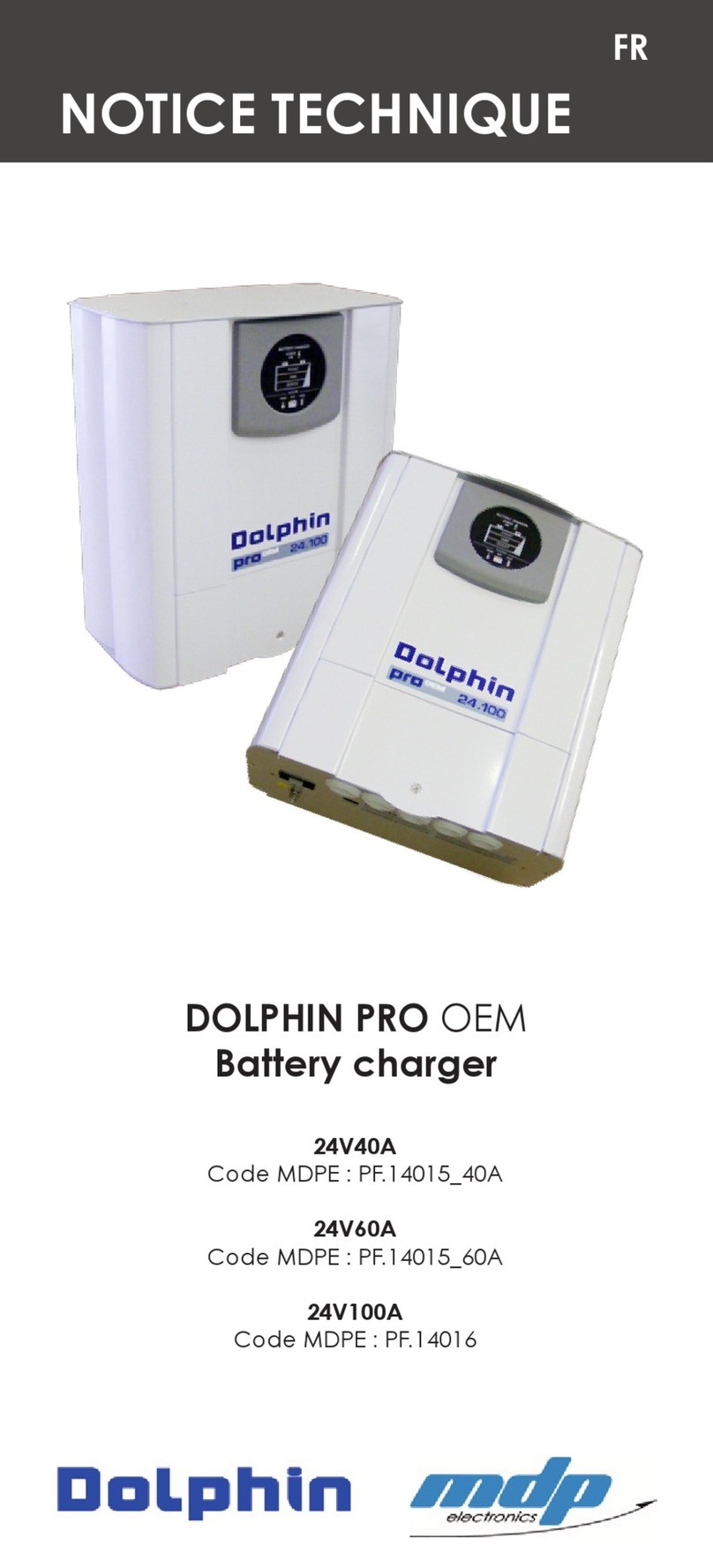
Dolphin pro HD+ 24V40A User manual

TECHNICAL MANUAL
EN
24V40A
REYA Code: 399.165
24V60A
REYA Code: 399.175
24V100A
REYA Code: 399.185
Battery charger

NOT-DOLPROHD-00
NOT-DOLPROHD-00
SAFETY PRECAUTIONS
TO PREVENT ANY RISK OF ELECTRIC
SHOCK OR FIRE, READ THIS MANUAL
CAREFULLY BEFORE INSTALLING THE
EQUIPMENT.
In the event of a problem or if you do not
understand, contact REYA.
This equipment is not designed for use
by people (including children) with
diminished physical, sensorial or mental
capacities or people without experience
or knowledge of such equipment, unless
they have received instructions in the
use of the equipment from a person
responsible for their safety or are under
the supervision of such a person. Ensure
that children are supervised to avoid
them playing with the device.
This equipment contains components
that may cause electric arcs or sparks,
when connecting cables for example. To
prevent any risk of re or explosion, do not
install this equipment close to inammable
materials, liquids or gases.
Installation precautions.
In order to prevent any risk of permanent
damage to the charger, the following
recommendations should be strictly
observed.
4The device must not be installed close
to a heat source.
4It must not be installed in an airtight or
badly-ventilated compartment.
4The cooling vents must not be
obstructed.
4Leave a free space of at least 10 cm
all around the case, to allow proper
convection.
4This device must not be exposed to
running water, water spray or dust of any
nature.
4It is recommended that the charger be
mounted vertically, with the cable exit
facing downwards.
4The case must not be mechanically
modied, for example by drilling additional
holes.
4In no sense is this device a toy. It should
therefore not be left in the hands of a
child.
Connection precautions.
To prevent any risk of electric shock or
irreversible damage to the equipment,
ensure you scrupulously respect the
recommendations below.
4The installation to which the device
is connected must be compliant with
applicable standards.
4The charger is designed to operate on
single phase mains power supplies 230V
50Hz or 115V 60Hz. 115V / 230V selection
is automatic. (230V only for the 24V100A
model)
4The mains power supply must have
a main power on/off switch, with
differential protection, to protect persons,
notably in cases of electric shock. Refer
to the charger electrical consumption
characteristics for the rating and selection
of the protection circuit breaker.
4Before connecting the charger, the
mains power cable grommet supplied in
the package carton must be assembled
and properly mounted on the case (using
the mounting nut), in the specic hole
provided.
4For safety, the charger EARTH terminal
(marked PE “Protective Earth”) must be
connected to the main site earth circuit
EN
SAFETY PRECAUTIONS
NOT-DOLPROHD-00
NOT-DOLPROHD-00
SAFETY PRECAUTIONS EN
(green/yellow wire in the mains power
cable). Refer to the wiring diagram for
more information.
4To prevent overheating, check that
cables are the specied section and that
connections are tight.
IMPORTANT: The charger is not protected
against batteries being connected with
reverse polarity. A wrong connection on
the battery side automatically destroys
the battery fuses and causes permanent
damage to the electronics board.
Startup precautions.
4In order to prevent any risk of electric
shock when switching on or during
operation, the protection cover must be
installed and properly screwed to the
mount.
4The charger complies with applicable
regulations concerning emitted
interference and immunity to external
interference (see EMC paragraph in the
Technical Specications section).
4When operating the charger, ensure
that it is not subjected to conducted or
radiated interference at levels above
the legal limits (e.g. charger too close to
a powerful transmitter), as such exposure
may cause malfunctions.
4Also, the charger emits conducted
and radiated interference at levels
compliant with applicable regulations.
Ensure that other equipment, used close
to the charger, is electro-magnetically
compatible, otherwise malfunctions may
be caused.
Charger serial number
The serial number is shown on the grey
or white label, bonded on one of the
sides of the charger. The serial number is
vertical. The rst two digits indicate the
year of manufacture (e.g. 15 for 2015),
followed by a letter indicating the month
of manufacture (e.g. C for the month
of March), followed by a 5-digit number
which is the charger number within the
series.
Important
Note on the choice of charge curve
Usingachargingcyclethatisincompatible
with the battery technology may seriously
damage the battery.
This is particularly true for cycles with
charge voltages that exceed the battery
manufacturer’s recommended charge
voltage.
Example: Considerable risk of battery
overheating and release of gases that
represent a health hazard.
Curve No. 9 is compatible with a LiFeSo4
battery, on condition that the battery
has a BMS (Battery Management System)
protection function.
You should refer to the battery
manufacturer’s recommendations when
selecting the charge cycle.
SAFETY PRECAUTIONS

NOT-DOLPROHD-00
NOT-DOLPROHD-00
INSTALLATION EN
Maintenance precautions
In order to prevent any risk of electric
shock during maintenance work, the
following recommendations should be
strictly observed before carrying out any
work:
4Maintenance work should only be
carried out by an appropriately qualied
technician.
4To avoid danger, damaged mains
power and/or battery cables should only
be replaced by a qualied person.
4Mains power must be disconnected
(cable or on/off switch).
4The -DC or -BAT battery side connection
must also be disconnected to avoid any
energy transfer.
4Wait 5 minutes for the high voltage
capacitors to discharge (on the
electronics board), before working inside
the case.
4Fuses should be replaced by fuses of
identical rating and performance.
WHEN YOU RECEIVE THE CHARGER
Package contents
4Charger.
4Installation manual.
4Mains power cable grommet with
its mounting nut (to be installed on
the case before connecting the
cables).
4Battery temperature sensor.
Preliminary checks
Check the charger identication
label, bonded on one of the case
sides, to ensure that the technical
data specied corresponds to your
requirement (mains power voltage,
charger rating, etc.).
Installation conditions
The charger is mounted using 4 screws, dia.
4mm (not supplied), on a support or wall that is
sufciently strong.
Check that the mounting screws used are
compatible with the type of mounting wall (resin,
wood, metal, etc.).
The charger should be positioned against the wall
and mounted rmly. Ideally, the charger should
be mounted vertically, with the cable exit facing
downwards. Leave a free space of at least 10 cm
all around the case, to allow optimum convection,
particularly on the cooling air inlet/outlet sides.
Inside the charger, the cooling air ows from right
to left when viewed from the front (see photo
below).
SAFETY PRECAUTIONS

NOT-DOLPROHD-00
NOT-DOLPROHD-00
EN
CONNECTIONS
INSTALLATION
CONNECTIONS
The charger connections are accessible by
removing the hatch in the front panel. To open
the hatch, remove the mounting screw. Then
rotate the hatch to remove it.
Before connecting the cables, the mains power
cable grommet must be installed and properly
mounted on the case, in its specic hole (hole on
left when viewed from the front of the charger).
The cable grommet is mounted on the case
using the plastic nut supplied. The nut is installed
inside the case. Ensure that the nut is properly
tightened.
CONNECTION DETAILS
Cooling air ow
Mains power
cable grommet
worm
cold

NOT-DOLPROHD-00
NOT-DOLPROHD-00
CONNECTIONS
Identication Functions
L AC mains power phase, max.
10mm² (wire colour code: brown or
black)
N AC mains power neutral, max.
10mm² (wire colour code: blue,
white or red)
AC mains power earth, max.
10mm² (wire colour code: green/
yellow or green)
-DC Battery negative (common), pin M8
(wire colour code: black)
+DC1 Main battery positive, pin M8 (wire
colour code: red)
+DC2 Auxiliary 2 battery positive, pin M8
(wire colour code: red)
+DC3 Auxiliary 3 battery positive, pin M8
(wire colour code: red)
CHARGE
SELECT
Curve and battery charge mode
selector, 10 positions (0 to 9)
BATTERY FUSES Battery protection fuses (on the
–DC supply)
EXT TOUCH CAN bus for TOUCH screen con-
nection
EXT COM1
& COM2
CAN bus for network operation
ID SELECT Conguration charger ID (network
operation)
TEMP SENSOR Battery temperature sensor
(2 wires no polarity, no direction)
RELAY Alarm dry contact
CONNECTIONS
AC CABLES AND CIRCUIT BREAKER
AC wiring
Check that cables are properly connected and
that the connections are tight.
For the mains power supply, it is preferable to use
an industrial cable, type HO7RNF. Observe the
recommendations below.
AC circuit breaker
The AC mains power line must have an on/
off switch with integral differential protection,
to protect persons, notably in cases of electric
shock.
Circuit breaker sensitivity must be 30mA. The
circuit breaker current rating must correspond to
the charger consumption. For this, observe the
recommendations below.
Nota : The charger has an internal protection fuse
on access L, which notably protects against a
general fault on the electronics board. As the fault
concerned is permanent, this fuse is not accessible for
maintenance.
Charger rating 230VAC 50Hz
Length < 5m (16ft)
115VAC 60Hz
Length < 5m (16ft)
24V 40A 2.5mm² / AWG13 4mm² / AWG11
24V 60A 2.5mm² / AWG13 4mm² / AWG11
24V 100A 4mm² / AWG11 6mm² / AWG9
Charger rating Mains power 230V
50Hz
Mains power 115V
60Hz
24V 40A 8A – 30mA 16A – 30mA
24V 60A 10A – 30mA 20A – 20mA
24V 100A 20A – 30mA -

NOT-DOLPROHD-00
NOT-DOLPROHD-00
CONNECTIONS EN
DC CABLES AND FUSES
DC wiring
Check that cables are properly connected and
that connections are tight.
Battery cables should be as direct and short as
possible.
Each battery output can deliver the full power of
the charger and all cables should therefore be of
identical section. Recommended cable sections
are specied below.
The chargers are equipped with waterproof
grommets with an “automatic” opening
function.
Press the centre of the membrane to thread the
cable through the grommet.
Charger rating Length < 2m (6ft) Length from 3 to
5m (10 to 16ft)
24V 40A 16mm² / AWG5 20mm² / AWG4
24V 60A 25mm² / AWG3 35mm² / AWG2
24V 100A 35mm² / AWG2 50mm² / AWG0-1
CONNECTIONS
AC CABLES AND CIRCUIT BREAKER
DC fuses
If fuses inside the charger have to be replaced,
they should be replaced by fuses with identical
characteristics and performance. Risk of
permanent damage to the charger.
It is necessary and strongly recommended that
a connections protection fuse be installed as
close as possible to each positive output from the
battery. This notably provides protection against
a short circuit and/or battery cable overheating,
for example due to cable sheath damage.
CHARGE CURVE SELECTION
The voltage, current and charge time parameters
are monitored, as a function of the initial battery
status, by up-to-date digital electronics, using a
RISC micro-controller, which
also monitors and optimises the
charging process, through the
exclusive “scanning charge”
function.
Charger rating
Charger internal
fuse
(–DC supply)
Battery external
fuse
(+BAT supply of
each battery)
24V 40A
3 x 25A 32V rapid
(mini automotive
fuse)
60A 32V rapid
24V 60A
3 x 25A 32V rapid
(mini automotive
fuse)
80A 32V rapid
24V 100A
5 x 30A 32V rapid
(mini automotive
fuse)
150A 32V rapid

NOT-DOLPROHD-00
NOT-DOLPROHD-00
CONNECTIONS EN
CONNECTIONS EN
Battery performance and life cycle are thus
enhanced.
The fully automatic charge cycles protect the
battery against overloads, and the charger can
thus be left permanently connected.
The charge programme is selected using the
“CHARGE SELECT” rotary selector on the charger
board. The selected programme number is
indicated by the arrow (programme No. 1 on the
photo above). The programme is selected using
a small at-head screwdriver.
CAUTION
Using a charging cycle that is incompatible with
the battery technology may seriously damage
the battery.
This is particularly true for cycles with charge
voltages that exceed the battery manufacturer’s
recommended charge voltage.
Considerable risk of battery overheating and
release of gases that represent a health hazard.
Curve No. 9 is compatible with a LiFeSo4 battery,
on condition that the battery has a BMS (Battery
Management System) protection function.
You should refer to the battery manufacturer’s
recommendations when selecting the charge
cycle. Toggle switch Thumb-wheel
Charger
Master
1: Master / 2 3 4: Network ID
Charge cycle according
to battery technology (10
positions)
Charger
Slave
No. 1
1: Slave / 2 3 4: Network ID ID Slave No. 1 (e.g. position 1)
Charger
Slave
No. 2
1: Slave / 2 3 4: Network ID ID Slave No. 2 (e.g. position 2)
Toggle switch Position 2: Determines whether the
charger is Master or Slave. Only ONE
Master per battery ID.
Position 2, 3, 4: Determine a battery ID,
i.e. a group of chargers operating on
one battery. Slave chargers attached to
a Master must have the same battery ID.
Thumb-wheel On Master charger: Determines the
charge curve for the Master and Slaves
operating on one battery.
On Slave charger: Determines the
charger ID (or the Slave No., from 0 to 9)
operating on one battery.
NETWORK MODE

NOT-DOLPROHD-00
NOT-DOLPROHD-00
SETTINGS SETTINGS EN
PROGRAMME PHASE VOLTAGE
0
Open
lead-
acid
V. BOOST
V. FLOAT
28.8V
26.4V
1
Sealed
lead-
acid
V. BOOST
V. FLOAT
28.4V
27.2V
2Lead-
calcium
V. BOOST
V. FLOAT
29.6V
27.6V
3“Delphi”
type
V. BOOST
V. FLOAT
30.8V
27.6V
Charge curve
5
Winter
storage
open
lead-
acid
V. BOOST
V. FLOAT
28.8V
26.4V
Charge curve
7GEL &
AGM
V. BOOST
V. FLOAT
28.8V
27.6V
Charge curve
8Power
supply V. FLOAT 27.2V
Charge curve
9
LiFeSo4
+ inte-
gral BMS
V. FLOAT 28.8V
Charge curve
6
Winter
storage
sealed
lead-
acid
V. BOOST
V. FLOAT
28.4V
27.2V
Charge curve
4
Type
“Op-
tima”
V. BOOST
V. MAX
V. FLOAT
29.6V
31.0V
27.6V
Charge curve

NOT-DOLPROHD-00
NOT-DOLPROHD-00
OPERATION OPERATION EN
BATTERY TEMPERATURE SENSOR
The temperature sensor allows the charge voltage
to be corrected as a function of the battery
temperature.
This results in a longer battery life cycle, mainly
in cases where the ambient temperature in the
battery room is high.
The sensor is screwed onto the main battery
positive terminal (generally ancillary). The 2 wires
are connected to the “TEMP SENSOR” connector
on the charger board (there is no polarity).
The compensation is around +/-25mV per °C for a
24V battery (see curves below).
TOUCH DISPLAY
This HD+ charger is equipped with an interactive
colour TOUCH screen. Screen functions are
described below.

NOT-DOLPROHD-00
NOT-DOLPROHD-00
OPERATION OPERATION EN

NOT-DOLPROHD-00
NOT-DOLPROHD-00
TECHNICAL SPECIFICATIONS TECHNICAL SPECIFICATIONS EN
Technical specications
24V 40A 24V 60A 24V 100A
MAINS POWER CHARACTERISTICS
Mains power voltage 115V 60Hz and/or
230V 50Hz (+/-15%)
230V
(+/-15%)
Power factor 0.9 typ.
Efciency 87 typ.
Inrush current < 30A, limited by
soft start < 60A
Consumption 14A/6A 15A/9A 15A
Active power 1350VA 2000VA 3500VA
Derating @ 115V Without
derating
70%
Pnom -
Mains power fuse
T20A
(6.3x32
mm)
T20A
(6.3x32
mm)
2xT20A
(6.3x32
mm)
BATTERY CHARGING CHARACTERISTICS
Number of outputs 3 independent supplies
Number of cycles 10 charge cycles (0 to 9), se-
lectable by rotary selector
Charge curves In general 3 statuses, type
I.U.Uo
Open lead-acid V.BOOST = 28.8V
V.FLOAT = 26.4V
Sealed lead-acid V.BOOST = 28.4V
V.FLOAT = 27.2V
Lead-calcium V.BOOST = 29.6V
V.FLOAT = 27.6V
“Delphi” type V.BOOST = 30.8V
V.FLOAT = 27.6V
“Optima”
type
V.BOOST = 29.6V then 31.0V
V.FLOAT = 27.6V
Winter storage open lead-
acid
V.BOOST = 28.8V
V.FLOAT = 26.4V
Winter storage sealed
lead-acid V.BOOST = 28.4V
V.FLOAT = 27.2V
24V 40A 24V 60A 24V 100A
Gel & AGM V.BOOST = 28.8V
V.FLOAT = 27.6V
Power supply V.FLOAT = 27.2V
LiFeSo4 + integral BMS V.FLOAT = 28.8V
Temperature
compensation
+/-25mV / °C
(by an external sensor)
Voltage tolerance +/-2%
Ripple < 1 % (BW < 20 MHz)
Maximum current 40A
(+/-5%)
60A
(+/-5%)
100A
(+/-5%)
-DC supply fuse
3 x F25A
(miniature automo-
tive fuse)
5 x 30A
(miniature
automo-
tive fuse)
PROTECTION
Overload in output “Current limited” type
Short circuit in output “Shutdown” type with automatic
restart when fault is cleared.
Output voltage too high “Shutdown” type with automatic
restart when fault is cleared.
Battery reverse polarity Output fuse
Internal temperature
too high
“Shutdown” type with automatic
restart when fault is cleared.
Battery temperature
too high
“Shutdown” type with automatic
restart when fault is cleared.
Temperature sensor
out of service
“Shutdown” type with automatic
restart when fault is cleared.
Mains power supply
general fault Mains power fuse
Battery supply
general fault Output fuses on –DC supply
Climatic conditions Tropicalised electronics board

NOT-DOLPROHD-00
NOT-DOLPROHD-00
TECHNICAL SPECIFICATIONS TECHNICAL SPECIFICATIONS EN
GENERAL INFORMATION
Operating
temperature
range
-10°C to +55°C
Storage tem-
perature range -20°C to +70°C
Relative Hu-
midity 10% to 90% (without condensation)
Convection Forced by thermostat-controlled fan
Case Wall mounted case in painted light alloy
Protection
index IP22
Mounting by 4 screws Ø 4mm
Dimensions
(Depth x Width
x Height)
128x346x358mm 196x346x358
Weight 6 kg 11.5 kg
Display TOUCH colour screen
Mains power
connector
3-point cage terminal for cable max. sec-
tion 10mm²
Battery con-
nectors Pins M8
Battery sensor
connector
2-point cage terminal for cable max. sec-
tion 1.5mm²
Alarm relay
connector
2-point cage terminal for cable max. sec-
tion 1.5mm²
CAN bus con-
nectors Micro-Fit (qty. 2) & RJ11 (qty. 1)
STANDARDS
EMC
EN55016-2-1, EN55016-2-1/A1, CISPR 16-2-1
EN 55016-2-3 + EN 55016-2-3/A1
IEC 61000-4-3 + A1 + A2
IEC 61000-4-2
IEC 61000-4-6
IEC 61000-4-5
IEC 61000-4-4
Environment
IEC 60068-2-30 & IEC 60068-2-1 (climatic
conditions)
IEC 60068-2-52 (salt spray)
Mechanical IEC 60068-2-6 & IEC 60068-2-64 (vibration)
test IEC publication No. 60529 (IP)
SAFETY EN 60335-1
DNV Classication “Control room,
Accommodation”
Dimensions
24V 40A - 24V 60A 24V 100A
Check that the mounting screws used are
compatible with the type of mounting wall (resin,
wood, metal, etc.).
The charger should be positioned against the wall
and mounted rmly.
[5
[
3RUWHGXJUDQG/\RQ
0,5,%(/&('(;
PGSFRQWDFW#PGSPRWRUFRP
7HO
)D[
3/$11
'X0RWHXUDX0RXYHPHQW
$
02',),&$7,216
'$7(6
,QG
&RGHV$UWLFOHV
23(
3URSULpWp0'3QHSHXWrWUHUHSURGXLWVDQVXQHDXWRULVDWLRQH[SUHVVHHWpFULWH
&RQWU{OH4XDOLWp
,QVWUXFWLRQVSDUWLFXOLqUHV
7ROpUDQFHV*pQpUDOHV
0DWLqUH
5$(
&UpDWLRQ
&RQIRUPH5R+6
GLPHQVLRQV
DQJOHV
pWDWVGHVXUIDFH
'2/352:+'
(
0(&
LQG
'pVLJQDWLRQ
+RUV,QGLFHV
[5
[
3RUWHGXJUDQG/\RQ
0,5,%(/&('(;
PGSFRQWDFW#PGSPRWRUFRP
7HO
)D[
3/$11
'X0RWHXUDX0RXYHPHQW
$
02',),&$7,216
'$7(6
,QG
&RGHV$UWLFOHV
23(
3URSULpWp0'3QHSHXWrWUHUHSURGXLWVDQVXQHDXWRULVDWLRQH[SUHVVHHWpFULWH
&RQWU{OH4XDOLWp
,QVWUXFWLRQVSDUWLFXOLqUHV
7ROpUDQFHV*pQpUDOHV
0DWLqUH
5$(
&UpDWLRQ
&RQIRUPH5R+6
GLPHQVLRQV
DQJOHV
pWDWVGHVXUIDFH
'ROSKLQSURZ+'
(
0(&
LQG
'pVLJQDWLRQ
+RUV,QGLFHV

NOT-DOLPROHD-00
NOT-DOLPROHD-00
WARRANTY WARRANTY EN
Warranty
TO PREVENT ANY RISK OF INCORRECT UTILISATION OF
THE CHARGER, CAREFULLY READ THE LIST OF EVENTS OR
POTENTIAL DEFECTS NOT COVERED BY THE PRODUCT
WARRANTY
4The charger is not protected against batteries
being connected with reverse polarity. Risk of
permanent damage to the charger.
4If the charger falls or is dropped, the impact
may permanently distort the case or cause the
failure of the internal fans or certain electronic
components.
4Modications to the case (in particular, drilling
additional holes) can deposit swarf or metal lings
on the electronics board, causing malfunctions or
permanent damage to the charger.
4Working on or modifying the electronics board
can result in operating modes for which the
charger was not designed, causing malfunctions
or permanent damage to the charger.
4Operating the charger on an unsuitable power
supply (generally a mains power voltage that is
too high).
4Accidental mains power overvoltage or
lightning strike, generally causing permanent
damage to the charger.
4Replacing fuses by fuses of an incorrect rating
can cause permanent damage to the charger.
4Obvious connection errors, causing permanent
damage to the charger.
4Water projections or run-off inside the charger
can cause permanent electronic malfunctions.
Precautions for scrapping
The charger contains electronic components
and materials that must be recycled at the end
of the charger life cycle, in order to protect the
environment.
All chargers, at the end of their life cycle, should
be returned to the local distributor or to a specialist
electronic hardware recycling company.
CE compliance
The charger complies with the applicable
European standards and bears CE marking. The
certicate of conformity is available on request.

For all information, contact:
REYA SAS
2599 route de la Fènerie
06580 Pégomas - France
Tel: +33 (0)4 93 90 47 00
Fax: +33 (0)4 93 47 42 57
e-mail: [email protected]
www.reya.com
This manual suits for next models
2
Table of contents
Other Dolphin Batteries Charger manuals

Dolphin
Dolphin COMBI SW User manual

Dolphin
Dolphin PRO OEM User manual

Dolphin
Dolphin 12V40A User manual

Dolphin
Dolphin PROLITE Series User manual

Dolphin
Dolphin 12V25A User manual

Dolphin
Dolphin PROLITE Series User manual

Dolphin
Dolphin All In One Series User manual

Dolphin
Dolphin Premium 12V60A User manual

Dolphin
Dolphin 12V25A User manual

Dolphin
Dolphin 12V 10A Owner's manual