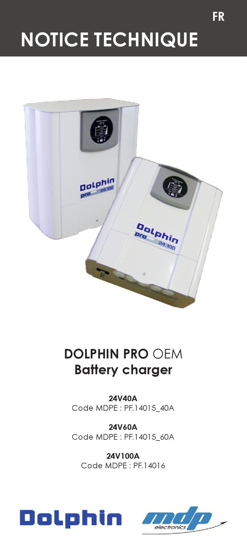
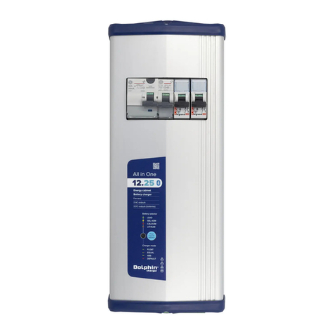
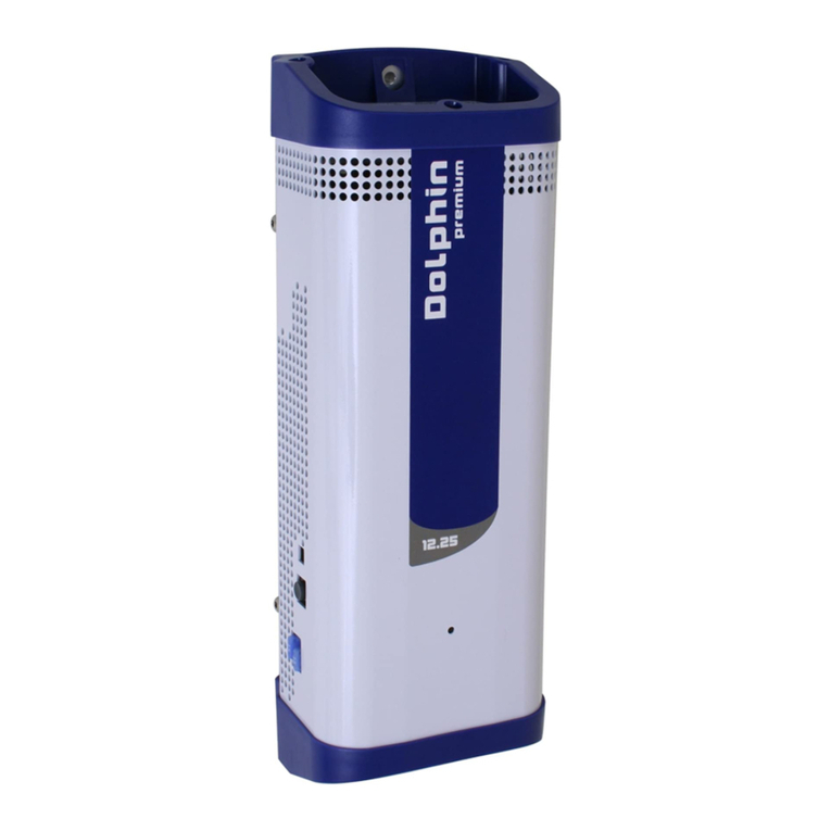
Dolphin Premium 12V60A User manual

EN
TECHNICAL MANUAL
Battery charger
premium 12V60A
399050 - PF.15053
premium 24V30A
PF.16070

NOT-PREMIUM900W-01
SAFETY PRECAUTIONS
TO PREVENT ANY RISK OF
ELECTRIC SHOCK OR FIRE,
READ THIS MANUAL CAREFULLY
BEFORE INSTALLING THE
EQUIPMENT.
In the event of any problems or misunderstandings,
please contact your dealer.
This equipment is not designed for use by people
(including children) with diminished physical,
sensorial or mental capacities, or people without
experience or knowledge of such equipment,
unless they have received prior instruction in the
use of the equipment from a person responsible
for their safety or are under the supervision of
such a person. Ensure that children are supervised
in order to prevent them playing with the device.
This equipment contains components that may
cause electric arcs or sparks, when connecting
cables, for example. To prevent any risk of fire or
explosion, do not install this equipment close to
flammable materials, liquids or gases.
Installation precautions
To prevent any risk of irreversible damage to the
equipment, ensure that you comply scrupulously
with the following recommendations.
4Do not install this device near a heat source.
4It should not be installed in an airtight or badly
ventilated area.
4All ventilation ducts must be unobstructed.
4Leave at least 10 cms / three inches clearance
around the device for proper ventilation.
4Mount in a vertical position, to create natural
ventilation for the charger. Note that the wiring
connections are at the bottom of the charger.
NOT-PREMIUM900W-01
SAFETY PRECAUTIONS
4All electrical connections to and from the
charger must remain accessible at all times.
4This system should not be exposed to water or
dust.
4It is strictly forbidden to tamper with the system
casing in any way.
4This device is not a toy and must be kept out of
the reach of children.
Connection precautions.
To prevent any risk of electric shock or irreversible
damage to the equipment, you should comply
strictly with the following recommendations.
4The installation to which this device is connected
must comply with the standards currently enforced
in the country of use..
4This device is designed to be connected to
220-240V 50Hz or 110-120V 60Hz single phase
circuits. 115V / 230V selection is automatic.
4In order to protect the occupants, the input point
must be attached to a dierential circuit breaker.
Please refer to the specific characteristics of the
circuit breaker.
4For security reasons, the system’s PE terminal
must strictly be connected to the installation’s
Earth (green/yellow wire in the cable section).
Please consult the wiring diagram.
4To prevent overheating, ensure the correct
connection and size of cables.
4The input cable must not exceed 3 meters (10
feet) and the output cable 1.5 meters (5 feet).
4All cable connections and connectors must
be maintained in good condition. Once the
connection of the AC cable has been completed,
EN

NOT-PREMIUM900W-01
it is imperative to fit the Winsta Wago snap on
security cover. See “Assembling the Shore Power
Connector”
Activation precautions
In order to avoid all risk of electric shock or
irreversible damage to the device, please follow
very carefully the following recommendations.
4Do not dismantle the device. The housing
(protection against fire) must be correctly mounted.
4This device complies with enforced standards;
regarding emitted interference, protection against
disturbances of external origins (refer to the
paragraph on EMC – Technical Specifications.)
4When in use, avoid submitting the device to
levels of interference, in particular electromagnetic
and conducted, superior to those legally permitted
(for example, the devise installed too close to an
emitter) as this may cause irreversible damage.
4This device emits interference (electromagnetic
and conducted) which complies with legal
standards. Ensure that materials used are
compatible i.e. susceptible, with this device in
order to avoid irreversible damage.
Device serial number
The serial number appears on the grey or white
sticker on one side of the device. This number is
aligned vertically and comprises a first number
indicating the year of manufacture (e.g.: 16 for
2016), a letter indicating the month of manufacture
(e.g.: C for the month of March), as well as a
5-figure number that is the product’s individual
serial number.
SAFETY PRECAUTIONS

NOT-PREMIUM900W-01
SAFETY PRECAUTIONS
Important
Note on the choice of charge curve
It is extremely important to choose the correct
charging curve, one which is appropriate for the
battery’s technology. An incorrect choice could
cause irreversible damage.
4This is particularly true for charging curves
where the charging voltage is higher than the
manufacturers’ recommended voltage levels.
4There is a high risk of overheating and emission
of noxious gases
4Charging curve 4 is compatible with LiFeSo4
batteries that have a BMS (battery management
system) installed.
4Itisessentialtoconsultthebatterymanufacturer’s
recommendations.
Maintenance precautions
To prevent any risk of electric shock during
maintenance operations, ensure that the following
recommendations are scrupulously observed
before performing any maintenance on the device:
4This device cannot be dismantled and thus the
PC board is inaccessible. It is strictly forbidden
to dismantle the housing for any reason. Electric
shock possible.
4In order to prevent risk of electric shocks
during maintenance, please follow closely all
recommendations below before any maintenance
begins.
4Any operation carried out to this eect must be
carried out by an authorized electrician.
In the event of damaged wires or cables, these
must be replaced by an authorized electrician.
The end user must not attempt to change them.
EN

NOT-PREMIUM900W-01
4The mains and battery connections must be
disconnected before any work is carried out in
order to avoid transfer of energy
4Fuses must be replaced by fuses that have the
same characteristics and performance levels.
SAFETY PRECAUTIONS
12V60A 24V30A
INPUT
Voltage 115V - 230V (+/- 15%)
Frequency 50Hz - 60Hz (+/- 10%)
Cos phi 0,9 typ
Eciency 80% typ
Mains consumption 10A 5A
Fuse T16A 250V 5x20mm
OUTPUT
Nb of outputs 3 isolated outputs
Nb charging
curves
4 possible charging curves.
Selection by external dip-switch
Curves types IUUo
Charging profile

NOT-PREMIUM900W-01
TECHNICAL SPECIFICATIONS EN
12V60A 24V30A
Charging curve 1
Lead open
Battery type: Lead open
V.boost = 14,2V
V.float = 13,2V
= 28,4V
= 26,4V
Charging curve 2
GEL
Battery type: GEL, AGM, Spiral
V.boost = 14,2V
V.float = 13,7V
= 28,4
= 27,4
Charging curve 3
Lead Calcium
Battery type: Lead Calcium
V.boost = 14,8V
V.float = 13,7V
= 29,6
= 27,4
Charging curve 4
Power Supply
or LiFeSo4
Battery type: Power supply or LiFeSo4
V.boost = 14,2V
V.float = 14,2V
= 28,4
= 28,4
Voltage precision +/- 2%
Ripple < 1% pp (BW < 20 MHz)
Max current 60A 30A
Fuse 3xF25A 32V
Automotive
3xF15A 32V
Automotive
Protections
Against output overload, output short circuit,
excessive internal temperature, excessive
battery temperature, output overvoltage,
battery reverse polarity (fuse)
GENERAL
Display Front LED or remote
TOUCH View (option)
Operating temp -10°C à +50°C
Storage temp -20°C à +70°C
Humidity 10% à 90% (without condensation)
Ventilation Forced fan cooling
External com CANbus
EMC EN61000-6-3 et EN61000-6-1
Security EN60335-2-29 (2002)
Housing White aluminium – wall mounted
Mounting 3 x 4mm screws
Dimensions 284 x 240 x 115mm
Weight 3,1 kg
Main acces 3 points, 20A 230V, 4mm2 max
Réf. : 770.813/G11-000 (WINSTA - WAGO)
BAT acces 4 points, 60A, 35mm2 max
TOUCH acces RJ11, 4 points
CAN acces Micro-Fit, 6 points
UART acces RJ12, 6 points

NOT-PREMIUM900W-01
TECHNICAL SPECIFICATIONS
Mode LED Status
Absorption Steady
yellow
The batteries are charging.
Time required to complete
Absorption mode varies
depending on the initial
status of the batteries, but is
limited to 6 hours.
Equalisation Yellow
blinking
The batteries are coming
to the end of the charging
cycle. Time required to
complete Equalization mode,
depending on the initial
status of the batteries, varies
from 30 minutes to 4 hours.
End of
Equalisation
Green
blinking
The batteries are almost
charged. Floating mode
will begin in less than 30
minutes.
Floating Green The batteries are completely
charged.
Internal
Temperature
fault
Red
fixed
The charger is on Standby
for a period of between 30
seconds and 10 minutes.
Once the fault has been
solved, the device will start
up again automatically.
Output
voltage fault
Red
blinking
The charger is on Standby
for a period of 30 seconds.
Once the fault has been
solved, the device will start
up again automatically.
Battery
fuse fault
Red
Flashing
The fuse should be
replaced.

NOT-PREMIUM900W-01
CONNECTIONS EN
Front LED
Main acces
TOUCH view_RJ11
CANbus_MicroFit
Cycle charge selector
UART_RJ12
BAT acces
Battery fuses
under the product

NOT-PREMIUM900W-01
CONNECTIONS
Assembling the shore power connector
Step 1
Remove approx 3 cm of the outer sheath
Remove approx 8 mm of the inner wires’ sheaths
Tinplate the bare copper ends
Step 2
Remove the security cap using an utility knife
Step 3
Pull the conductor through the pre latched strain
relief housing
Step 4
Open the clamp with a screwdriver and insert the first
cable up to the stop. Repeat this step for all three
cables
Step 5
Latch the connector on to the strain relief housing
Step 6
Snap together the upper and lower parts of the strain
relief housing and tighten it using the screw
Wiring diagram
Dispatching
BusBar (-)

NOT-PREMIUM900W-01
Check that the mounting screws used are
compatible with the type of mounting wall (resin,
wood, metal, etc.). The charger should be positioned
against the wall and mounted firmly.
DIMENSIONS EN
ECHELLE 1 : 5
240
284
3x
5,5
100
261 11,5
115
3x 17,3
21 Porte du grand Lyon
01707 MIRIBEL CEDEX
Tel : (33) 04 72 01 83 00
Fax : (33) 04 72 01 83 09
PLAN N°
A3
MODIFICATIONS
DATES
Ind.
Codes Articles :
OPE
Propriété MDP, ne peut être reproduit sans une autorisation expresse et écrite
Contrôle Qualité
Instructions particulières :
Tolérances Générales
Matière :
00
BEN
Création
07/03/2016
1:2
(Conforme RoHS)
dimensions :
angles :
états de surface :
DOL PRO 900W
MEC-13-786
ind 00
Désignation :
(Hors Indices)

NOT-PREMIUM900W-01
Warranty
TO PREVENT ANY RISK OF INCORRECT USE OF THE
DEVICE, CAREFULLY READ THE LIST OF POTENTIAL
EVENTS OR FAULTS NOT COVERED BY THE PRODUCT
WARRANTY
4This device is not protected against battery polarity
reversals. Risk of irreversible damage to the equipment.
4Should the device be dropped or fall this could cause
irreversible distortion of the housing as well as a “crash”
of internal fans and certain electronic components.
4Modifications to the housing (additional holes in
particular) could result in the scattering of swarf or
metal filings onto the circuit board and, consequently, in
malfunctions or irreversible damage to the equipment.
4Interference with or modifications to the circuit
board could result in operating modes not originally
anticipated, and consequently, in malfunctions or
irreversible damage to the equipment.
4Powering the device from an unsuitable energy
source (as a general rule, mains supply voltage that is
too high).
4Accidental original mains supply surge or lightning
strike generally causing irreversible damage to the
equipment.
4Replacement of fuses with fuses with dierent
characteristics that could cause irreversible damage to
the equipment.
4Obvious connection errors causing irreversible
damage to the equipment.
4Water spray or running water inside the device that
could result in irreversible electronic malfunctions.
WARRANTY

NOT-PREMIUM900W-01
Precautions for scrapping
This device contains electronic components and
materials that must be recycled at the end of the
product’s usable life, for environmental reasons.
At the end of their usable lives all devices must
therefore be returned either to the local distributor or
entrusted to a specialist electronic equipment recycling
company.
EC compliance
This device complies with the applicable European
standards and has an EC mark. Its certificate of
compliance is available on request.
WARRANTY EN

info@dolphin-charger.com
www.dolphin-charger.com
This manual suits for next models
4
Table of contents
Other Dolphin Batteries Charger manuals

Dolphin
Dolphin 12V25A User manual

Dolphin
Dolphin PROLITE Series User manual

Dolphin
Dolphin PRO OEM User manual

Dolphin
Dolphin 12V10A User manual

Dolphin
Dolphin pro HD+ 24V40A User manual

Dolphin
Dolphin All In One Series User manual

Dolphin
Dolphin 12V25A User manual

Dolphin
Dolphin COMBI SW User manual

Dolphin
Dolphin PROLITE Series User manual

Dolphin
Dolphin 12V 10A Owner's manual