dom-security.com
4
System
System: create master ID card / add device to a system
(yellow-red-green-yellow-blue-yellow)
If you hold a master card in front of a new terminal
device and thus connect it to a new system, the
signal sequence shown opposite is displayed. The
device can also be added to the system using the
access control soware.
System: remove master ID card / delete device from system
To disconnect the device from the master card and
thus remove it from the system, hold the master card
in front of the terminal device twice in succession.
Please wait for the respective signal sequence. The
third time, hold the master card in front of the
reading field of the terminal device and leave it there
until the terminal device flashes yellow four times in
succession (up to 15 seconds). You can now remove
the master card from the reading field; the device will
reset itself and indicate this with the signal sequence
shown opposite.
The device can also be removed via soware or app.
The signal sequence is the same.
The device then restarts.
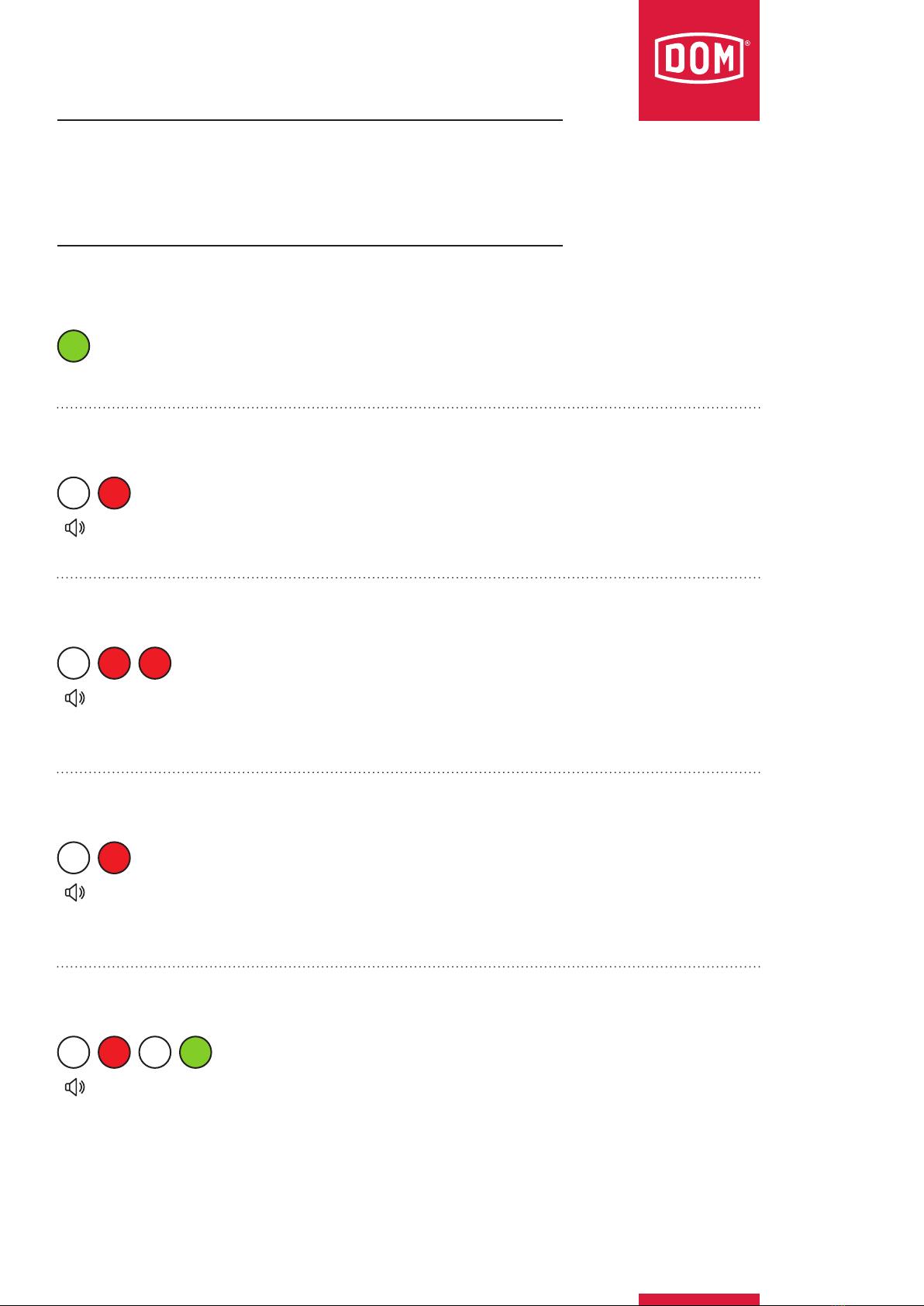
First signal sequence: (blue-green-green)
Second signal sequence: (green-red)
Third signalling: (yellow-red-green-yellow-yellow)
Holding a transponder in front of a new device
(yellow-blue-yellow-blue-yellow (continuously accompanied by the beep tone))
If a transponder is held in front of a device that has
not yet been initialised, the device flashes yellow and
blue alternately.
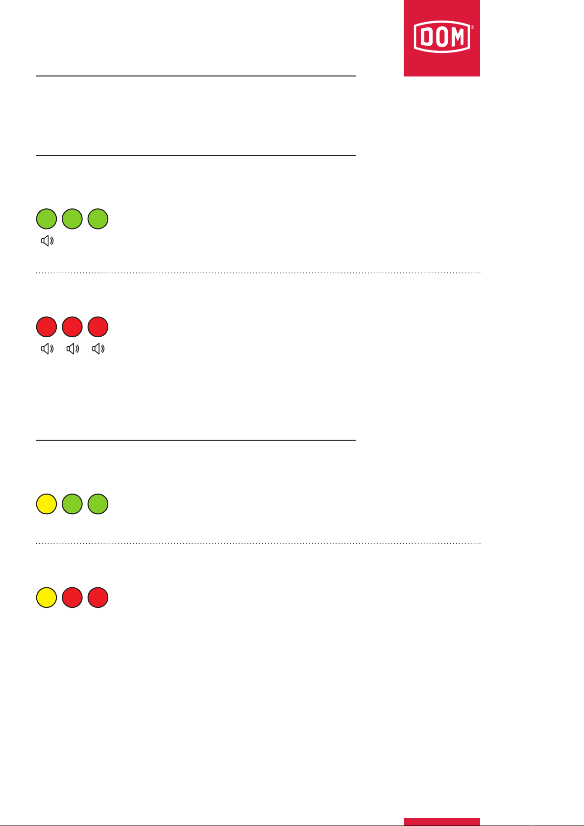
Creating a transponder with master card or programming card
Hold the master card or programming card in front of
the device, then hold the transponders that are to be
authorised in front of the device one at a time and
wait for each one to flash green once. Finally, the
device will flash green three times.
(yellow-red-green-yellow-blue-yellow-green)
ELS/ENiQ® signalling