5
UNITECNIC 1150 - INSTRUCTION MANUAL
Only the red screws can be unscrewed.
Any other internal disassembly is
prohibited. (cancellation of warranty)
!Attention
4. Number of terms change.
(Be careful not to lose any springs)
■It is possible to reduce the number of
terms in a combination by replacing
one of the red tumblers with a blue
tumblers provided.
■It is possible to increase the number
of terms in a combination by
replacing one of the blue tumblers
by a red provided.
5. Close the mecanism
■ Push to the max, the tumblers into
their housing, then replace the plate.
6. Carry out several tests
■Enter the new code.
Always proceded by “C”.
So it is possible to turn the handle.
7. Test the free access mode
■(If it is kept)
Dial the combination then press the
free access key, the handle is then
released indenitely. To return to
controlled access mode, press the
free access key, then “C”.
In case of non-operation.
Check that only the red tumblers
are pushed when entering the code
on the keypad: They are visible
through the holes in the spring plate.
(The order of the terms of the code
doesn’t matter).
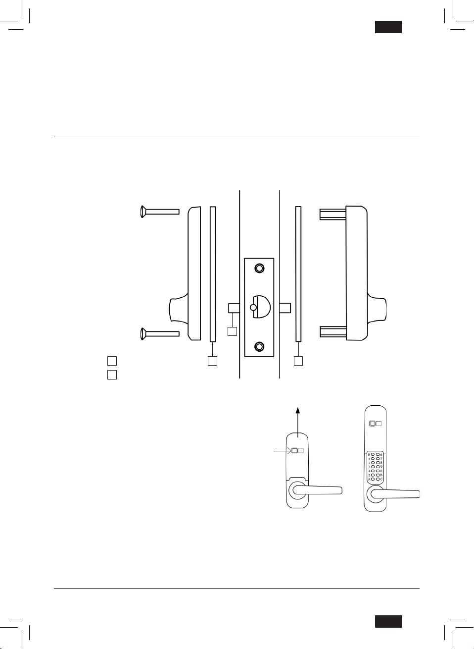
Replace the
4 red screws