5
641515, 641516, 641535, 651515 & 651516 Installation Instructions
a. This supply line must be located in the front
portion of the 14-1/4" x 14-1/4" (±1/8") open-
ing.
b. Make sure that at least 15" of supply wire
extends into the roof opening.
c. Inamultiplezoneinstallation,thiswiringis
requiredinonly oneofthe14-1/4"x 14-1/4"
(±1/8") openings.
3. If a Remote Temperature Sensor is used, the
connector end must be routed from the sensor
location to the roof opening of the system which
it will control. Make sure that at least 15" of the
sensor cable extends into the roof opening. Refer
to the Remote Sensor Instructions for details of
the installation.
4. If a furnace is to be controlled by the system, the
twofurnacethermostatleadsmustberoutedtothe
roof opening of the unit that will control it. Make
sure that at least 15" of the furnace thermostat
wires extend into the roof opening.
5. If an Energy Management System (load shed
feature) is to be used with the control, two wires
must be routed to the roof opening of the zone to
bemanaged.Thesignalrequiredforthisfunctionis
anormallyopenrelaycontact.WhentheEMScalls
for the compressor to shut off, the relay contacts
should close. Make sure at least 15" of the EMS
wires extend into the roof opening.
6. Route a 4-conductor control cable from the Com-
fort Control Center™ mounting position into the
14-1/4" x 14-1/4" (±1/8") roof opening. Make sure
that at least 15" of the wire extends into the roof
opening and 6" extend from the wall at the mount-
ingpositionoftheComfortControlCenter™.See
Section E-2.
7. Intheeventthatotherunitsareinstalled(additional
zones)anadditional4-conductorcontrolcablemust
beroutedtotheotherunits.Makesurethatatleast
15" of the wire extends into the roof opening. See
FIG. 18.
8. If an automatic generator start kit (AGS) will be in-
stalled,a4-conductorcontrolcablemustberouted
from the last unit (zone) to location of the control
box that will operate theAGS system. FollowAGS
kit instructions for installation.
E. DometicComfort ControlCenter™&Cable
Installation
1. Location
a. IfthesystemistobeusedWITHOUTaRemote
Temperature Sensor, the proper location of
the Comfort Control Center™ is very impor-
tanttoensure thatitwill provideacomfortable
RV temperature. Observe the following rules
when selecting a location:
•LocatetheComfortControlCenter™54"
above the floor.
•Install the Comfort Control Center™ on
a partition, not on an outside wall.
•NEVERexposeittodirectheatfromlamps,
sun or other heat producing items.
•Avoid locations close to doors that lead
outside, windows or adjoining outside
walls.
•Avoid locations close to supply registers
and the air from them.
b. If the system is to be used WITH a Remote
Temperature Sensor in ALL zones, the
Comfort Control CenterTM may be mounted
anywherethatisconvenientinthecoach.Tryto
avoid hard to reach and hard to see areas.
•Refer to the instructionsprovidedwiththe
Remote Temperature Sensor for details
of installation.
c. A 3/8" diameter hole will be needed to route
the cable through the wall. See Section D-3.
2. Control Cable Installation
A4-conductorcontrolcablemustberoutedfromthe
roof opening to the Comfort Control CenterTM.
a. Choose the shortest, most direct route from
the 14-1/4" x 14-1/4" (±1/8") opening to the
Comfort Control CenterTM location selected.
Leave 6" of cable extending through the wall.
See Section D-6.
b. The control cable that should be used is a flat,
4-conductor telephone cable.
c. Thecontrol cablemustbeterminatedwithtwo
(2) RJ-11-6C4P telephone connectors. Refer
to the crimp tool manufacture for crimping
instructions.
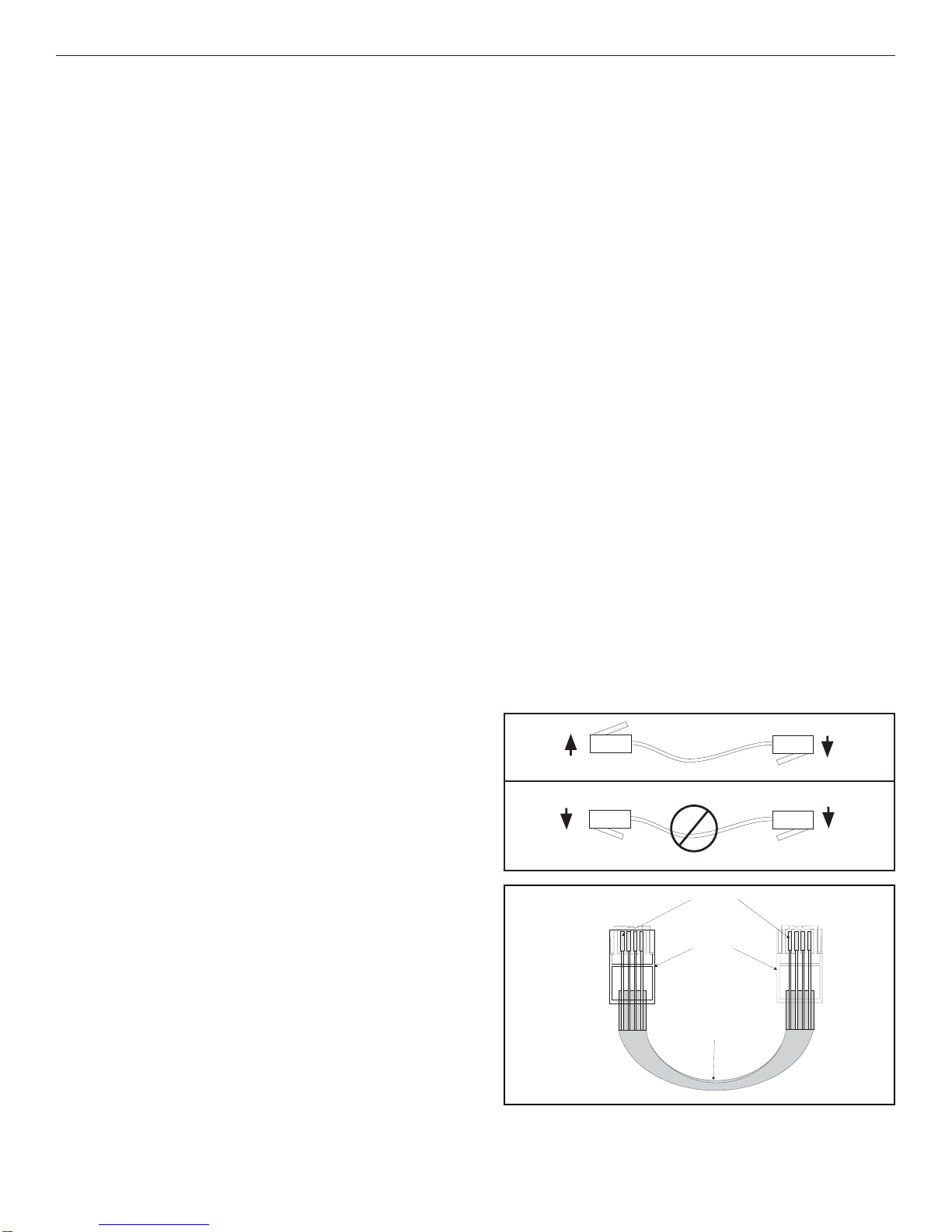
Important:RJ-11-6C4Pconnectorsmustbeinstalled
as shown in FIG. 4, 5 & 6.
FIG. 4
FIG. 5
Flat Four Conductor Cable
RJ-11-6C4P Connector
Pin 1
FIG. 6
Black
Green
Red
Yellow
Black
Green
Red
Yellow