manuals.online logo
Brands
  1. Home
  2. •
  3. Brands
  4. •
  5. Dormakaba
  6. •
  7. Door Opening System
  8. •
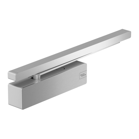
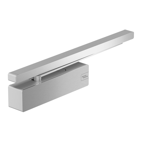
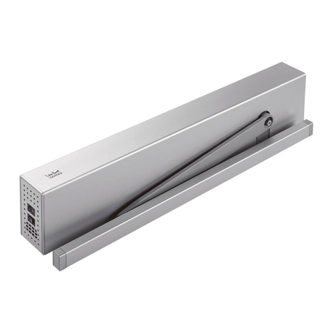
  9. Dormakaba TS 98 XEA User manual

Dormakaba TS 98 XEA User manual

EN
G-EMF XEA
Mounting instructions
Contents
1 About this manual 2
1.1 Information about the manual 2
1.2 Target groups 2
1.3 Provided documents 2
1.4 Symbols and abbreviations used 2
1.4.1 Safety instructions 2
1.4.2 Further labeling 2
1.4.3 Tool symbols 2
1.5 Glossary 2
2 Safety 2
2.1 Intended use 2
2.2 Limitation of liability 2
2.3 Prerequisites for the operation of catching
devices 2
3 Product description 3
3.1 EMF 3
3.2 Technical data 3
4 Installation 3
4.1 Prepare the mounting of the slide rail 3
4.2 Mount the slide rail 3
4.3 Mount the door closer 3
5 Start up 4
5.1 Set the fixture point 4
5.2 Set the release force 4
5.3 Mount the paneling 4
5.4 Check locking 4
6 Operating 4
6.1 Open and lock door 4
6.2 Close door 4
7 Dismounting, recycling and disposal 4
dormakaba Deutschland GmbH
DORMA Platz 1
D‑58256 Ennepetal
17
0432‑CPR‑00026‑60 EN 1155 1997/A1: 2002/AC:2006 3 8 3‑5 1 1 4
DOP_0148
WN 059411 45532 – 2017-10
1 About this manual
1.1 Information about the
manual
This instruction is part of the product. The instruction
comprises important instructions for safe operation.
Therefore, the instruction must be carefully read
before using the product. This instruction must be
kept during the service life of the product and must
be passed on with the product. This instruction
describes the installation, startup, maintenance and
disassembly of the slide rail system G‑EMF XEA. The
text of the instruction is supported by figures in a
separate figure part. The chapter numbers in the text
can be found again top left in the figures in the figure
part. There is not always a figure in the figure part to
support a chapter in the text.
1.2 Target groups
The installation, startup, maintenance and
disassembly must only be carried out by skilled staff
which has been authorized by dormakaba. The
operation of the slide rail system may be carried out
by any person who is mentally and physically able.
1.3 Provided documents
• Installation manual
• Data sheet about the use of arrest systems
1.4 Symbols and abbreviations
used
1.4.1 Safety instructions
ATTENTION
This signal word indicates a situation of
potential risk, which could lead to damage
to property or the environment if not
averted.
1.4.2 Further labeling
2.1. Step‑by‑step graphics
1 2 Position numbers of parts
The illustration shows the mounting
DIN‑L on the hinge side. Mounting
DIN‑R takes place mirror‑inverted.
Illustration shows mounting DIN‑R on
the hinge side. Mounting DIN‑L takes
place mirror‑inverted.
1.4.3 Tool symbols
Allen wrench,
e.g. wrench size 3
1.5 Glossary
EMF Electromechanical locking device
RMZ Smoke detection panel
TS Door closer
2 Safety
2.1 Intended use
The catching device is used to keep open door leaves.
The locking mechanism is used in conjunction with
external RMZ to keep open fire and smoke protection
closures. Fire and smoke protection closures must
meet the building regulation requirements ‘’self‑
locking’’. The electromechanical locking device is no
substitution for a door stop. The locking device is
released manually or via an external RMZ.
2.2 Limitation of liability
The manufacturer does not assume liability for
damages in the following events:
• Nonobservance of this instruction.
• A deviating application of the intended use.
• The assignment of insufficiently skilled staff.
• Unauthorized modifications.
• Technical alterations.
• The use of spare parts which are not authorized.
2.3 Prerequisites for the
operation of catching devices
The use of catching devices is subject to special
regulations by reason of official admission standards.
These regulations refer in particular to the inspection,
the continuing surveillance and the maintenance.
Follow the details from the data sheet about the use
of catching devices. Additional requirements apply for
the use as fire and smoke protection closures in
conjunction with the external RMZ and RM. A
separate verification of suitability is required for the
respective fire / smoke protection door.
2G-EMF XEA 2017-10
dormakaba
WN 059411 45532
About this manualInstallation manual
3 Product description
The GSR‑EMF XEA comprises the following
components:
• Slide rail systems
• Built‑in electromechanical locking device
The G‑EMF XEA is intended for the mounting on the
hinge side or the opposite hinge side. The GSR‑EMF
XEA is suitable for DIN‑L and DIN‑R doors.
When mounting in the opposite hinge side,
a proof of suitability in conjunction with the
respective
fire/ smoke protection door is required.
3.1 EMF
The EMF is an electromechanical locking mechanism
with adjustable release force, which enables locking
the door without spring back. After a cut‑off of power
supply, the locking device disengages and the door will
be closed securely through the door closer.
3.2 Technical data
Operating voltage: 24V DC
in France also 48VDC
Power consumption: 1.4 W
in France also 2.2 W
Duty cycle: 100 % ED
Release torque: approx. 25 – 65 Nm at 90°
opening angle (dependent
on the set closing force on
the closer)
Door opening angle: max. 140°
The drive happens via an external RMZ.
4 Installation
The mounting of the slide rail system takes place
directly on the base of the door lintel or optionally
with an additional mounting plate (extras).
4.1 Prepare the mounting of the
slide rail
The slide rail can be mounted in two different options:
Option A= Mounting on the hinge side
Option B= Mounting on the opposite hinge side
1. Prepare the power supply (24 V/48 V DC) from the
smoke detection panel to the EMF in version with
EMF.
2. Mark the fixing points for the closer and the slide
rails according to the hole pattern.
3. Drill the holes.
4. Drill the hole for the connection cable
24/48‑V‑Anschlusskabel with Ø8mm.
5. Lay the lines.
4.2 Mount the slide rail
1. Mount the base.
2. Insert all cables into the intended openings.
3. Lead the connection cable downwards.
4. Tighten the slide rail.
5. Clamp the 24/48‑V connection cable to the slide
rail.
6. Put the cable into the hollow space of the end
piece.
4.3 Mount the door closer
1. Mount the door closer and lever to the door leaf
according to the enclosed instructions for the
door closer.
2. Adjust the door closer.
3G-EMF XEA 2017-10
dormakaba Installation manual
WN 059411 45532
Product description
dormakaba Deutschland GmbH
DORMA Platz 1 58256 Ennepetal Germany T: +49 2333 793-0 F: +49 2333 793-4950 www.dormakaba.com
5 Start up
5.1 Set the fixture point
ATTENTION
Risk of cable damage
While setting the fixture points cables might
be damaged.
• Pay attention not to jam the connecting
cables.
1. Feed the power supply (24 V/48 V DC).
2. Open the fixed leaf until it clicks.
3. Unbolt the screws of the locking unit(s).
4. Open the door leaves to the desired hold open
bracket.
If the EMF is pushed to the end of the slide rail,
the cable clips must be removed.
5. Unbolt the screws of the locking unit(s).
6. Place the door stop into the position of the fixture
points selected.
5.2 Set the release force
ATTENTION
Risk of damage to the catching device
Setting a release force too high may result
in damage to the door hinges and the
fastening elements of the door closing
system.
• Set the release force depending on the
door width and the selected size of the
closing contact.
• According to the DIN EN 1155 the release
force must not be less than 40 Nm at a
door opening angle of 90° and not more
than 120 Nm.
1. Set the release force.
2. Control the release force.
5.3 Mount the paneling
1. Attach the end caps.
2. Mount the paneling of the glide rail.
5.4 Check locking
1. Open the door leaf and lock it.
2. Cut off power supply.
‣ The door leaf is released and closes.
6 Operating
6.1 Open and lock door
1. Open door leaves to the fixture point.
‣ The door leaves remain standing after letting
go.
6.2 Close door
1. Press shut the door leaf or press the optional
manual release button.
‣ The door leaf is released and closes.
7 Dismounting,
recycling and
disposal
Dismantling is the same procedure in reverse and
must be carried out by qualified personnel.
The product must be disposed of environmentally
sound. Electro‑technical parts and batteries must not
be disposed of as household waste. Dispose of
electro‑technical parts and batteries in the arranged
acceptance and collection points.
Translation of the original manual, subject to change without notice

Other manuals for TS 98 XEA

6

This manual suits for next models

1

Other Dormakaba Door Opening System manuals
Dormakaba PT 22 User manual

Dormakaba

Dormakaba PT 22 User manual

Dormakaba RTS88 User manual

Dormakaba

Dormakaba RTS88 User manual

Dormakaba ED250 User manual

Dormakaba

Dormakaba ED250 User manual

Dormakaba 8900 EMR User manual

Dormakaba

Dormakaba 8900 EMR User manual

Dormakaba TS 98 XEA User manual

Dormakaba

Dormakaba TS 98 XEA User manual

Dormakaba 8900 IS User manual

Dormakaba

Dormakaba 8900 IS User manual

Dormakaba ED50 User manual

Dormakaba

Dormakaba ED50 User manual

Dormakaba TS 98 XEA User manual

Dormakaba

Dormakaba TS 98 XEA User manual

Dormakaba ED900 User manual

Dormakaba

Dormakaba ED900 User manual

Dormakaba 8900 T User manual

Dormakaba

Dormakaba 8900 T User manual

Dormakaba PORTEO User manual

Dormakaba

Dormakaba PORTEO User manual

Dormakaba ED50LE User manual

Dormakaba

Dormakaba ED50LE User manual

Dormakaba 7400 DS User manual

Dormakaba

Dormakaba 7400 DS User manual

Dormakaba 8600 FH User manual

Dormakaba

Dormakaba 8600 FH User manual

Dormakaba ED900 User manual

Dormakaba

Dormakaba ED900 User manual

Dormakaba ED900 User manual

Dormakaba

Dormakaba ED900 User manual

Dormakaba Muto Premium XL120 User manual

Dormakaba

Dormakaba Muto Premium XL120 User manual

Dormakaba TS 92 G BASIC EN 1-4 User manual

Dormakaba

Dormakaba TS 92 G BASIC EN 1-4 User manual

Dormakaba 8900 FH User manual

Dormakaba

Dormakaba 8900 FH User manual
Dormakaba ED900 User manual

Dormakaba

Dormakaba ED900 User manual

Dormakaba ED100 User manual

Dormakaba

Dormakaba ED100 User manual
Dormakaba ED50 User manual

Dormakaba

Dormakaba ED50 User manual

Dormakaba RTS Series User manual

Dormakaba

Dormakaba RTS Series User manual

Dormakaba C800 User manual

Dormakaba

Dormakaba C800 User manual
Popular Door Opening System manuals by other brands

Dorma TS 93 Series manual

Dorma

Dorma TS 93 Series manual

Assa Abloy SARGENT 281 Series manual

Assa Abloy

Assa Abloy SARGENT 281 Series manual

Lamp FD35EV installation manual

Lamp

Lamp FD35EV installation manual

cinetto PB15 Assembly instructions

cinetto

cinetto PB15 Assembly instructions

Dorma ITS 96 EN 2-4 Fixing instructions

Dorma

Dorma ITS 96 EN 2-4 Fixing instructions

CAME MI1010 quick start guide

CAME

CAME MI1010 quick start guide

DITEC OLLY C Installation and maintenance manual

DITEC

DITEC OLLY C Installation and maintenance manual

CAME VER06DES manual

CAME

CAME VER06DES manual

cinetto PS10 Assembly instructions

cinetto

cinetto PS10 Assembly instructions

Woelm HELM GT-L 80 installation instructions

Woelm

Woelm HELM GT-L 80 installation instructions

tau 150SESP manual

tau

tau 150SESP manual

Andersen SmoothControl+ Left Hand Hydraulic Closer installation guide

Andersen

Andersen SmoothControl+ Left Hand Hydraulic Closer installation guide

Bortoluzzi slider M50 manual

Bortoluzzi

Bortoluzzi slider M50 manual

DITEC DAB105 Technical manual

DITEC

DITEC DAB105 Technical manual

KROME 910DA installation instructions

KROME

KROME 910DA installation instructions

ECO Schulte ETS 42 Operator's manual

ECO Schulte

ECO Schulte ETS 42 Operator's manual

LCN 4031 CUSH installation instructions

LCN

LCN 4031 CUSH installation instructions

Von Duprin 33/35A installation instructions

Von Duprin

Von Duprin 33/35A installation instructions

manuals.online logo
manuals.online logoBrands
  • About & Mission
  • Contact us
  • Privacy Policy
  • Terms and Conditions

Copyright 2025 Manuals.Online. All Rights Reserved.