Bodyguard® 1000
PASS (Personal Alert Safety System) Instructions for Use
Bodyguard® is a registered trademark of Dräger 3358687 (A3-D-P) Page 1 of 2
1 For your safety
1.1 General safety statements
● Before using this product, carefully read the instructions for use.
● Strictly follow the instructions for use. The user must fully understand
and strictly observe the instructions. Use the product only for the
purposes specified in the Intended Use section of this document.
● Do not dispose of the instructions for use. Ensure that they are
retained and appropriately used by the product user.
● Only fully trained and competent users are permitted to use this
product.
● Comply with all local and national rules and regulations associated
with this product.
● Only trained and competent personnel are permitted to inspect, repair
and service the product. Dräger recommends a Dräger service
contract for all maintenance activities and that all repairs are carried
out by Dräger.
● Use only genuine Dräger spare parts and accessories, or the proper
functioning of the product may be impaired.
● Do not use a faulty or incomplete product, and do not modify the
product.
● Notify Dräger in the event of any component fault or failure.
1.2 Definitions of alert icons
Alert icons are used in this document to provide and highlight text that
requires a greater awareness by the user. A definition of the meaning of
each icon is as follows:
WARNING
Indicates a potentially hazardous situation which, if not avoided,
could result in death or serious injury.
CAUTION
Indicates a potentially hazardous situation which, if not avoided,
could result in physical injury or damage to the product or
environment. It may also be used to alert against unsafe practices.
NOTICE
Indicates additional information on how to use the product.
2 Description
2.1 Product overview
The Bodyguard®1000 is a battery powered Personal Alert Safety System
that provides audible and visible alarm signals. Audible signals are loud
and easily recognized with varying alarm patterns to distinguish between
different warning conditions. The alarm is from an electronic sounder that
uses the tally slots as amplification chambers to provide clear and loud
alarm signals.
Visible signals are provided by red, blue, green and amber LEDs on the
casing. During use the unit displays a flashing green LED that indicates
active mode, and pulsing blue LEDs that are used as a visual identification
signal (or buddy-beacon) for fellow team members.
The unit is configured as either a button version or a tally version. The main
difference between the version types is the alarm arming and cancelling
method:
● Button version – the buttons on the side of the unit are used to arm and
cancel automatic alarms (a tally is not supplied with button versions).
● Tally version (BS 10999:2010) – the tally is removed or inserted to arm
and cancel alarms.
● Tally version (with button cancel) – the tally is removed to arm the
alarms. Alarms are cancelled by inserting the tally or by pressing the
buttons on the side of the unit.
The unit is fixed on to the outside of protective clothing or equipment using
one of three different fixing options. The standard fixing is a low-profile
harness clamp. An alternative (supplied with the unit) is an adaptor which
attaches the unit to a universal accessory clip. An optional alternative
(supplied as an accessory) is a crocodile clip with combined wire D-ring.
2.1.1 Distress alarms
The main function of the unit is to provide automatic and manual distress
alarms. The automatic distress alarm uses an internal motion sensor and
timer to measure the time that wearer has been motionless, in order to
indicate that the wearer may be unconscious or trapped. The automatic
distress alarm activates a pre-alert ( ) and a full alarm ( ) at
predetermined timed intervals when the wearer does not move in excess
of normal breathing movement. The manual alarm is operated by pressing
the yellow button ( ), to allow the wearer to signal for help or attention.
2.1.2 Thermal exposure alarm
Protective clothing insulates the wearer from the thermal environment,
making it difficult to appreciate the level of heat or thermal exposure. The
Bodyguard®1000 includes a thermal sensor that monitors exposure and
starts a timer at a set start temperature (the default start temperature is
40 °C). Once the timer has started, two thermal exposure alarms activate
at time-weighted temperature thresholds. The alarms warn the user of a
relatively long period of exposure to slightly elevated temperatures, or of a
short period of exposure in high temperature situations.
The thermal sensor can be disabled, or the start temperature can be
configured, to meet the individual operational needs of the user using
Dräger PC Link (see Section 2.1.3).
2.1.3 Radio frequency link
The Bodyguard®1000 is equipped with radio frequency (RF)
communication circuitry that enables wireless reading and reprogramming
of the unit. Information includes unit identity, a record of events (datalog),
parameter maintenance and firmware reprogramming. The parameter
settings that are configurable include enabling/disabling of alarms, motion
alarm times, alarm sounds, etc. The alarm parameters described in this
document are the default settings for the unit.
The radio frequency link requires the Dräger PC Link. Contact Dräger for
details.
2.2 Intended use
The Bodyguard®1000 is intended for use by firefighters, other emergency
services, and industrial users engaged in fire fighting, rescue and other
hazardous duties. The unit provides clear, distinct and easily recognized
alarm signals that indicate wearer immobilization, a call for help or
attention, or warn of excessive thermal exposure. Distress alarms can be
used by rescue teams to pinpoint the position of the source of the alarm.
2.3 Limitations on use
A limitation of the automatic distress alarm is that the motion sensor
detects movement or vibration to which the wearer is subjected, and may
not activate if the wearer is motionless on a moving platform (for example,
on moving or vibrating machinery).
Special Conditions for Safe Use:
The recessed label is made from aluminium foil. The end user shall
exercise care to ensure that the label is not subject to impact or abrasion
during use as this may cause incendive sparks.
The metal fixing clamp is an isolated conductive part with a capacitance of
6 pF, exceeding the values permitted by Table 9 of EN60079-0: 2012 for
Group II equipment. This should be taken into consideration by the user as
an electrostatic discharge risk in determining suitability for use.
2.4 Approvals
The European standards, guidelines, and directives according to which
this product is approved are specified in the declaration of conformity (see
declaration of conformity or www.draeger.com/product-certificates).
2.5 Marking and symbols
CAUTION
Do not use marker pens or apply paint, and do not scratch or
engrave the unit, as this may damage the unit or invalidate
approvals. It is recommended that any personal marking of the unit
is made using adhesive labels.
BRXX-1234 Dräger serial number
Left-hand button and active LED
Right-hand button
Low battery LED
3 Use
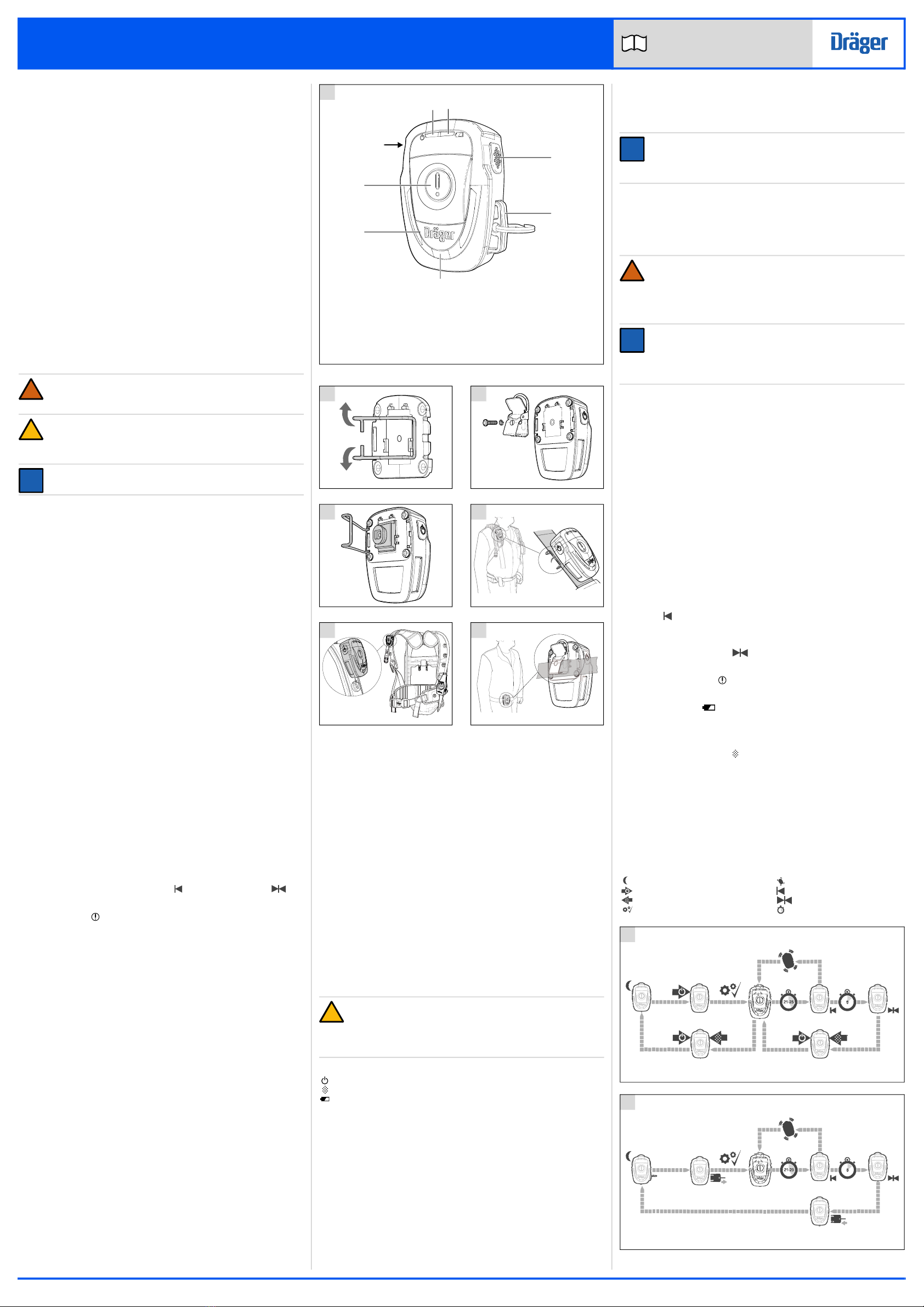
3.1 Preparation for use
3.1.1 Initial assembly
The rear cover and batteries are supplied loose (unfitted) with the unit.
Install them before first use (see Section 3.4.2).
If the unit is supplied with the crocodile clip accessory, fit the clip as follows:
1. Remove the harness clamp from the rear cover (Fig 2).
2. Install the batteries and rear cover as normal (see Section 3.4.2).
3. Connect the crocodile clip accessory (Fig 3). Gently tighten (nip up)
the screw using a T10 driver. Dräger recommend a torque of 0.8 Nm
(0.6 lbf ft) – do not over tighten.
If fitting the unit to a universal accessory clip, fit the adaptor as follows:
1. Install the batteries and rear cover as normal (see Section 3.4.2).
2. Fit the universal accessory clip adaptor and secure in place with the
harness clamp (Fig 4).
NOTICE
Only secure the universal accessory clip adaptor to the unit with
the harness clamp. Do not use a screw, such as the one supplied
with the crocodile clip accessory.
3.1.2 Preparation for use
1. Install the batteries if necessary (see Section 3.4.2).
2. Carry out a functional test (see Section 3.4.1).
3. Fit the unit to a breathing apparatus harness strap or to protective
clothing.
WARNING
Fitting the unit inside protective clothing would insulate the thermal
sensor from the thermal environment and delay alarm activation,
risking over exposure to high temperatures. Fix the
Bodyguard®1000 outside any protective clothing and ensure that
the sensor is clear of obstructions.
NOTICE
The optimum fitting positions are on the front of the wearer at the
shoulder (Fig 5 and Fig 6) or waist (Fig 7). The shoulder position
may expose the thermal sensor to slightly higher temperatures, and
is recommended for fire fighting operations.
3.2 During use
3.2.1 Operating modes and functions
Use and activation of alarms, and any evacuation and recovery
procedures, should be in line with existing command and control
procedures.
Sleep mode – When the unit is switched off it enters a sleep mode
(awaiting an activation signal). The automatic alarms are disabled and all
LEDs are off. The manual distress alarm can be activated from sleep
mode.
Active mode – When the unit is switched on, and passes the self check,
a start-up signal occurs (four beeps, and brief illumination of all LEDs) and
then the unit enters the active mode indicated by a flashing green LED
(every second). Automatic alarms are enabled and the buddy-beacon
signal is on.
Error alert – If the unit fails the self check during start-up, or if a hardware
failure occurs during use, the error alert activates (five beeps plus high-
frequency flash of the amber LED).
Pre-alert ( ) – No movement sensed for 21–25 seconds. Activates a
repeating, increasing-volume, triple-beep alarm tone accompanied by
alternating red and blue LEDs.
Automatic distress alarm ( ) – No movement sensed for 8 seconds
of pre-alert. Activates the full alarm signal.
Manual distress alarm ( ) – Pressing the button activates the full alarm
signal.
Low battery alert ( ) – Flashing amber LED and beep every five
seconds.
Thermal exposure alarm 1 – Lower time/temperature threshold reached.
Activates a short repeating double-beep alarm tone and flashing red LEDs.
Press the right-hand button ( ) to silence the alarm.
Thermal exposure alarm 2 – Higher time/temperature threshold reached.
Activates the full alarm signal.
Buddy-beacon – Blue LEDs pulsing at low frequency.
Full alarm signal – A high-pitched pulsating alarm signal accompanied by
alternating red and blue LEDs.
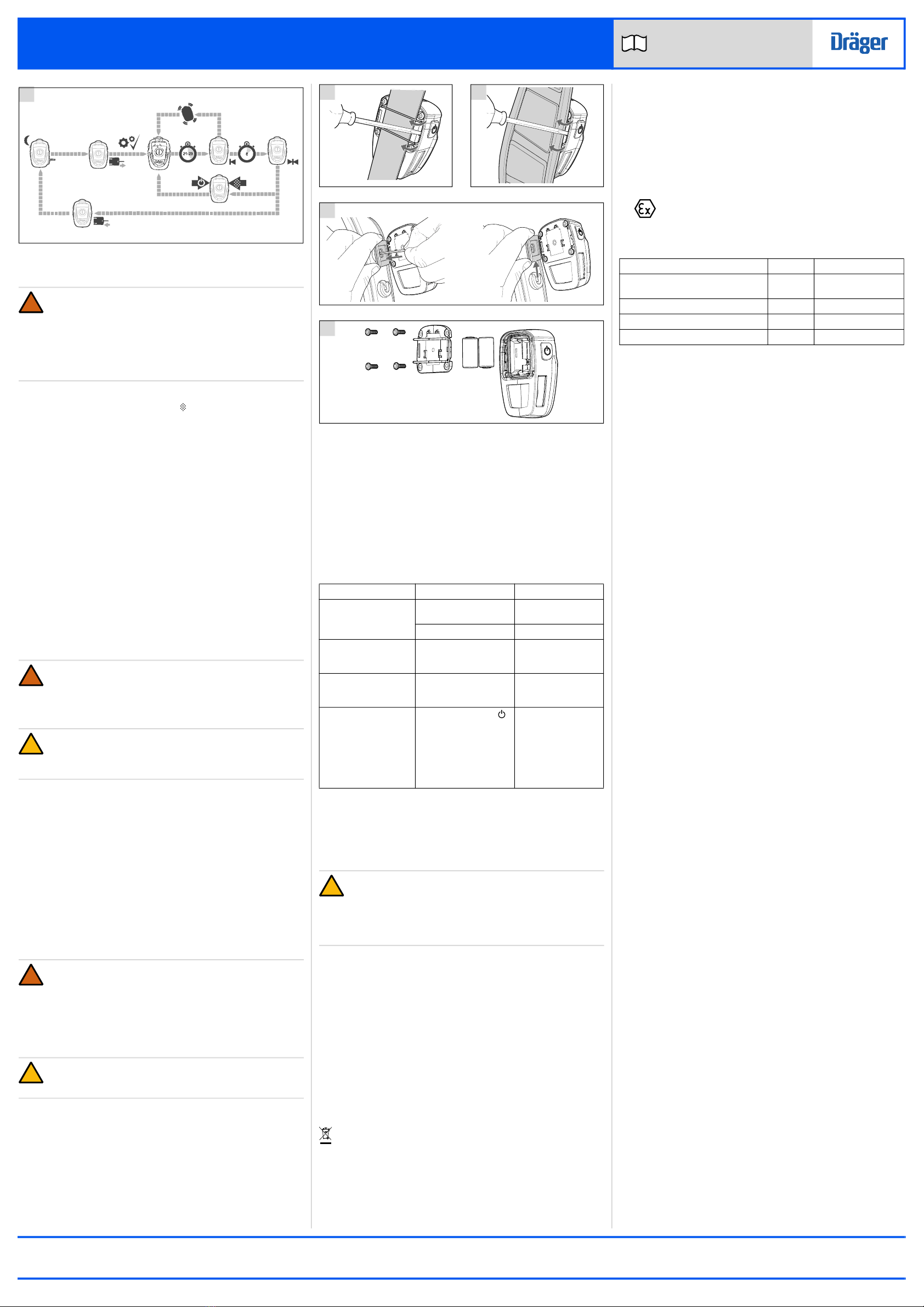
3.2.2 Automatic distress alarms
Key
Sleep Movement
Press left-hand button Pre-alert
Press right-hand button Full alarm
Self check Time in seconds
!
8
3325
Button version
9
3326
Tally version (BS 10999:2010)
3
4
1 2
6
8
7
5
1
3316
1 Active LED 5 Thermal sensor
2 Low battery LED 6 LED panel
3 Right-hand button 7 Manual alarm button
4 Tally (option) 8 Left-hand button
3338
2
3324
3
5470
4
3339
5
5471
6
3337
7