Dragino CPL01 User manual

CPL01 LoRaWAN Outdoor Pulse/Contact Sensor
last modified by Xiaoling
on 2022/07/01 18:01

User Manual for LoRaWAN End Nodes - CPL01 LoRaWAN Outdoor Pulse/Contact Sensor
Table of Contents
1. Introduction .......................................................................................................................................................................... 4
1.1 What is CPL01 LoRaWAN Pulse/Contact Sensor .................................................................................................... 4
1.2 Features .......................................................................................................................................................................... 4
1.3 Installation ....................................................................................................................................................................... 5
1.4 Storage & Operation Temperature ............................................................................................................................. 5
1.5Applications .............................................................................................................................................................. 6
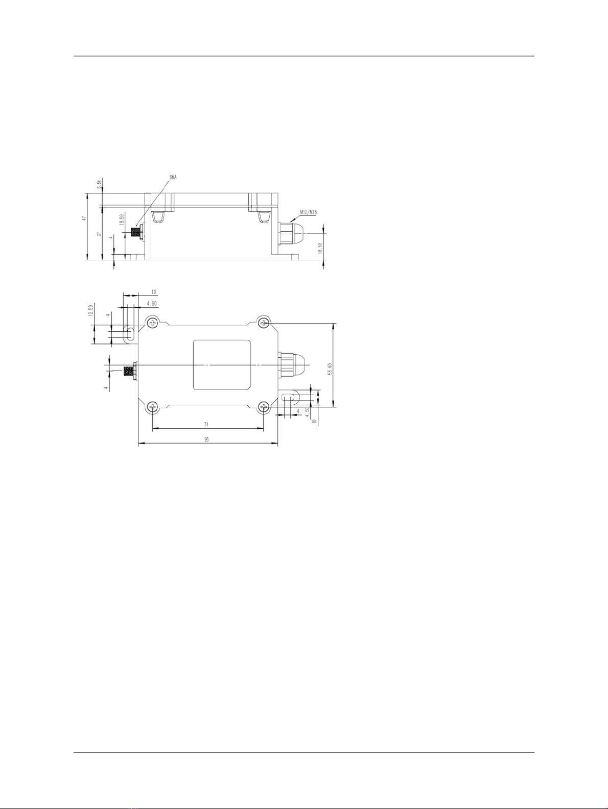
1.6Mechanical ...................................................................................................................................................................... 6
1.7Pin Definitions and Switch ............................................................................................................................................ 7
1.7.1Pin Definition ............................................................................................................................................................. 7
1.7.2 Jumper JP2(Power ON/OFF) ................................................................................................................................ 7
1.7.3BOOT MODE / SW1 ............................................................................................................................................... 7
1.7.4 Reset Button ............................................................................................................................................................ 7
1.7.5 LED ............................................................................................................................................................................ 7
2. Operation Mode .................................................................................................................................................................. 8
2.1 How it works? ................................................................................................................................................................ 8
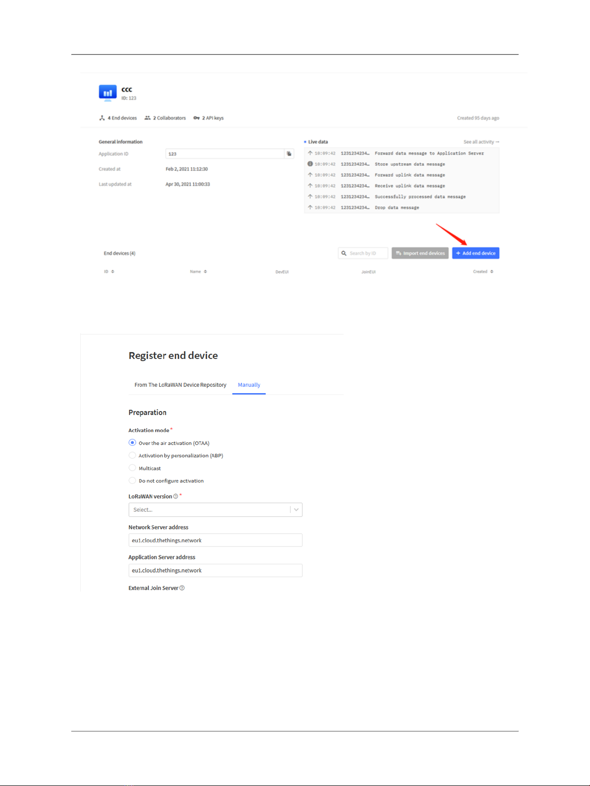
2.2 Example to use for LoRaWAN network ...................................................................................................................... 8
2.3 Uplink Payload ............................................................................................................................................................. 12
2.3.1 Device Status, FPORT=5 .................................................................................................................................... 12
2.3.2 Sensor Configuration, FPORT=4 ........................................................................................................................ 13
2.3.3 Real-Time Open/Close Status, Uplink FPORT=2 ............................................................................................. 15
2.3.4 Historical Door Open/Close Event, FPORT=3 .................................................................................................. 16
2.4 Datalog Feature ........................................................................................................................................................... 17
2.4.1 Unix TimeStamp .................................................................................................................................................... 17
2.4.2 Set Device Time .................................................................................................................................................... 18
2.4.3 Poll sensor value ................................................................................................................................................... 18
2.4.4 Decoder in TTN V3 ............................................................................................................................................... 19
2.5 Show data on Datacake ............................................................................................................................................... 19
3. Configure CPL01 via AT Command or LoRaWAN Downlink ..................................................................................... 24
3.1 Set Transmit Interval Time ........................................................................................................................................ 25
3.2 Set Password .............................................................................................................................................................. 25
3.3 Quit AT Command ...................................................................................................................................................... 26
3.4 Enable / Disable Alarm ............................................................................................................................................... 26
3.5 Alarm Base on Timeout .............................................................................................................................................. 26
3.6 Clear Flash Record ..................................................................................................................................................... 27
3.7 Set the sensor mode .................................................................................................................................................. 27
3.8 Set trigger mode ......................................................................................................................................................... 28
3.9 Set the calculate flag .................................................................................................................................................. 28
3.10 Set count number ..................................................................................................................................................... 28
4. Battery & how to replace ................................................................................................................................................ 29
4.1 Battery Info ................................................................................................................................................................... 29
4.1.1 Battery Note ........................................................................................................................................................... 29
4.2 Replace Battery ........................................................................................................................................................... 29
4.3 Battery Life Analyze .................................................................................................................................................... 30
5. FAQ .................................................................................................................................................................................... 30
5.1 How to use AT Command to configure CPL01 ....................................................................................................... 30
5.2 How to upgrade the firmware? .................................................................................................................................. 31
5.3 How to change the LoRa Frequency Bands/Region? ............................................................................................ 31
6. Trouble Shooting .............................................................................................................................................................. 32
6.1 AT Commands input doesn't work .......................................................................................................................... 32
7. Order Info .......................................................................................................................................................................... 32
8. Packing Info ...................................................................................................................................................................... 32
9. Support .............................................................................................................................................................................. 32
Page 2 / 32 - last modified by Xiaoling on 2022/07/01 18:01

User Manual for LoRaWAN End Nodes - CPL01 LoRaWAN Outdoor Pulse/Contact Sensor
Table of Contents:
•1. Introduction
•1.1 What is CPL01 LoRaWAN Pulse/Contact Sensor
•1.2 Features
•1.3 Installation
•1.4 Storage & Operation Temperature
•1.5Applications
•1.6Mechanical
•1.7Pin Definitions and Switch
•1.7.1Pin Definition
•1.7.2 Jumper JP2(Power ON/OFF)
•1.7.3BOOT MODE / SW1
•1.7.4 Reset Button
•1.7.5 LED
•2. Operation Mode
•2.1 How it works?
•2.2 Example to use for LoRaWAN network
•2.3 Uplink Payload
•2.3.1 Device Status, FPORT=5
•2.3.2 Sensor Configuration, FPORT=4
•2.3.3 Real-Time Open/Close Status, Uplink FPORT=2
•2.3.4 Historical Door Open/Close Event, FPORT=3
•2.4 Datalog Feature
•2.4.1 Unix TimeStamp
•2.4.2 Set Device Time
•2.4.3 Poll sensor value
•2.4.4 Decoder in TTN V3
•2.5 Show data on Datacake
•3. Configure CPL01 via AT Command or LoRaWAN Downlink
•3.1 Set Transmit Interval Time
•3.2 Set Password
•3.3 Quit AT Command
•3.4 Enable / Disable Alarm
•3.5 Alarm Base on Timeout
•3.6 Clear Flash Record
•3.7 Set the sensor mode
•3.8 Set trigger mode
•3.9 Set the calculate flag
•3.10 Set count number
Page 3 / 32 - last modified by Xiaoling on 2022/07/01 18:01

User Manual for LoRaWAN End Nodes - CPL01 LoRaWAN Outdoor Pulse/Contact Sensor
•4. Battery & how to replace
•4.1 Battery Info
•4.1.1 Battery Note
•4.2 Replace Battery
•4.3 Battery Life Analyze
•5. FAQ
•5.1 How to use AT Command to configure CPL01
•5.2 How to upgrade the firmware?
•5.3 How to change the LoRa Frequency Bands/Region?
•6. Trouble Shooting
•6.1 AT Commands input doesn't work
•7. Order Info
•8. Packing Info
•9. Support
1. Introduction
1.1 What is CPL01 LoRaWAN Pulse/Contact Sensor
The Dragino CPL01 is a LoRaWAN Contact Sensor. It detects open/close status and uplink to IoT server via
LoRaWAN network. user can see the dry contact status, open time, open counts in the IoT Server.
CPL01 is powered by 8500mAh Li-SOCI2 battery, It is designed for long term use up to 10 years. (Actually Battery
life depends on the use environment, update period.)
The CPL01 will send periodically data every day as well as for each dry contact action. It also counts the contact
open times and calculate last open duration. User can also disable the uplink for each open/close event, instead,
device can count each open event and uplink periodically.
CPL01 has the open alarm feature, user can set this feature so device will send Alarm if the contact has been open
for a certain time.
CPL01 is designed for outdoor use. It has a weatherproof enclosure and industrial level battery to work in low to high
temperatures.
Each CPL01 is pre-load with a set of unique keys for LoRaWAN registration, register these keys to LoRaWAN
server and it will auto connect after power on.
*Battery life depends on how often to send data, please see battery analyzer.
1.2 Features
• LoRaWAN v1.0.3 Class A protocol.
• Frequency Bands: CN470/EU433/KR920/US915/EU868/AS923/AU915/IN865/RU864
• Open/Close detect
• Open/Close statistics
• 8500mAh industrial battery(none-rechargeable)
• AT Commands to change parameters
• Uplink on periodically and open/close event
• Datalog feature
• Remote configure parameters via LoRa Downlink
• Firmware upgradable via program port
• Wall Mountable
• Outdoor Use
Page 4 / 32 - last modified by Xiaoling on 2022/07/01 18:01

User Manual for LoRaWAN End Nodes - CPL01 LoRaWAN Outdoor Pulse/Contact Sensor
1.3 Installation
Connect CPL01 to an Open Close sensor like below. So it can detect the open/close event.
1.4 Storage & Operation Temperature
-40°C to +85°C
Page 5 / 32 - last modified by Xiaoling on 2022/07/01 18:01

User Manual for LoRaWAN End Nodes - CPL01 LoRaWAN Outdoor Pulse/Contact Sensor
1.5Applications
• Open/Close Detection
• Pulse meter application
• Dry Contact Detection
1.6Mechanical
Page 6 / 32 - last modified by Xiaoling on 2022/07/01 18:01

User Manual for LoRaWAN End Nodes - CPL01 LoRaWAN Outdoor Pulse/Contact Sensor
1.7Pin Definitions and Switch
1.7.1Pin Definition
CPL01 is pre-configured to connect to two external wires. The other pins are not used. If user wants to know more
about other pins, please refer to the user manual of LSN50v2 at: http://www.dragino.com/downloads/index.php?
dir=LSN50-LoRaST/
1.7.2 Jumper JP2(Power ON/OFF)
Power on Device when putting this jumper.
1.7.3BOOT MODE / SW1
1) ISP: upgrade mode, device won't have any signal in this mode. but ready for upgrade firmware. LED won't work.
Firmware won’t run.
2) Flash: work mode, the device starts to work and send out console output for further debug
1.7.4 Reset Button
Press to reboot the device.
1.7.5 LED
It will flash:
1. Boot the device in flash mode
2. Send an uplink packet
Page 7 / 32 - last modified by Xiaoling on 2022/07/01 18:01

User Manual for LoRaWAN End Nodes - CPL01 LoRaWAN Outdoor Pulse/Contact Sensor
2. Operation Mode
2.1 How it works?
Each CPL01 is shipped with a worldwide unique set of OTAA keys. To use CPL01 in a LoRaWAN network, user
needs to input the OTAA keys in the LoRaWAN network server. So CPL01 can join the LoRaWAN network and
start to transmit sensor data.
2.2 Example to use for LoRaWAN network
This section shows an example of how to join the TTN V3 LoRaWAN IoT server. Usages with other LoRaWAN IoT
servers are similar.
• In this use case, the CPL01 is connect to a dry contact sensor to detect the open/close event and send the
status to the LoRaWAN server. The CPL01 will uplink different types of messages to the LoRaWAN server.
See Uplink payload for detail.
Assume the DLOS8 is already set to connect to the TTN V3 network. We need to add the CPL01 device in TTN V3:
Step 1: Create a device in TTN V3 with the OTAA keys from CPL01.
Each CPL01 is shipped with a sticker with the default device EUI as below:
Page 8 / 32 - last modified by Xiaoling on 2022/07/01 18:01

User Manual for LoRaWAN End Nodes - CPL01 LoRaWAN Outdoor Pulse/Contact Sensor
Users can enter these keys in the LoRaWAN Server portal. Below is the TTN V3 screenshot:
Add APP EUI in the application.
Page 9 / 32 - last modified by Xiaoling on 2022/07/01 18:01

User Manual for LoRaWAN End Nodes - CPL01 LoRaWAN Outdoor Pulse/Contact Sensor
Page 10 / 32 - last modified by Xiaoling on 2022/07/01 18:01

User Manual for LoRaWAN End Nodes - CPL01 LoRaWAN Outdoor Pulse/Contact Sensor
Add APP KEY and DEV EUI
Step 2: Power on CPL01
Put the jumper to power on CPL01 and it will auto-join to the TTN V3 network. After join success, it will start to
upload sensor data to TTN V3 and the user can see it in the panel.
Page 11 / 32 - last modified by Xiaoling on 2022/07/01 18:01

User Manual for LoRaWAN End Nodes - CPL01 LoRaWAN Outdoor Pulse/Contact Sensor
2.3 Uplink Payload
Uplink payloads have two types:
• Open/Close Status: Use FPORT=2
• Other control commands: Use other FPORT fields.
The application server should parse the correct value based on FPORT settings.
2.3.1 Device Status, FPORT=5
Include device configure status. Once CPL01 Joined the network, it will uplink this message to the server. After that,
CPL01 will uplink Device Status every 12 hours.
Users can also use the downlink command(0x26 01) to ask CPL01 to resend this uplink. This uplink payload also
includes the DeviceTimeReq to get time.
Example parse in TTNv3
Page 12 / 32 - last modified by Xiaoling on 2022/07/01 18:01

User Manual for LoRaWAN End Nodes - CPL01 LoRaWAN Outdoor Pulse/Contact Sensor
•Sensor Model: For CPL01, this value is 0x0E
•Firmware Version: 0x0100, Means: v1.0.0 version
•Frequency Band:
*0x01: EU868
*0x02: US915
*0x03: IN865
*0x04: AU915
*0x05: KZ865
*0x06: RU864
*0x07: AS923
*0x08: AS923-1
*0x09: AS923-2
*0x0a: AS923-3
*0x0b: CN470
*0x0c: EU433
*0x0d: KR920
*0x0e: MA869
•Sub-Band:
• AU915 and US915:value 0x00 ~ 0x08
• CN470: value 0x0B ~ 0x0C
• Other Bands: Always 0x00
•Battery Info:
Check the battery voltage.
Ex1: 0x0B45 = 2885mV
Ex2: 0x0B49 = 2889mV
2.3.2 Sensor Configuration, FPORT=4
CPL01 will only send this command after getting the downlink command (0x26 02) from the server.
Page 13 / 32 - last modified by Xiaoling on 2022/07/01 18:01

User Manual for LoRaWAN End Nodes - CPL01 LoRaWAN Outdoor Pulse/Contact Sensor
•TDC: (default: 0x001C20)
Uplink interval for the total pulse count, default value is 0x001C20 which is 7200 seconds = 2 hours.
•Disalarm: (default: 0)
If Disalarm = 1, CPL01 will only send uplink at every TDC periodically. This is normally use for pulse meter
application, in this application, there are many disconnect/connect event, and platform only care about the total
number of pulse.
If Disalarm = 0, CPL01 will send uplink at every TDC periodically.
•Keep Status & Keep Time
Shows the configure value of Alarm Base on Timeout Feature
•Trigger mode (default: 0)
If Trigger mode = 0, count close to open event.
If Trigger mode = 1, count open to close event.
Page 14 / 32 - last modified by Xiaoling on 2022/07/01 18:01

User Manual for LoRaWAN End Nodes - CPL01 LoRaWAN Outdoor Pulse/Contact Sensor
2.3.3 Real-Time Open/Close Status, Uplink FPORT=2
CPL01 will send this uplink after Device Status once join the LoRaWAN network successfully. And CPL01 will:
periodically send this uplink every 2 hours, this interval can be changed.
Uplink Payload totals 11 bytes.
Real-Time Open/Close Status, FPORT=2
Size (bytes) 1 3 3 4
Value Status & Alarm Total pulse The last open duration
(unit: min)
Unix TimeStamp
•Calculate Flag
The calculate flag is a user define field, IoT server can use this filed to handle different meter with different pulse
factor. For example, if there are 100 water meters, meter 1 ~50 are 1 liter/pulse and meter 51 ~ 100 has 1.5 liter/
pulse.
User can set calculate flag to 1 for meter 1~50 and 2 for meter 51 ~ 100, So IoT Server can use this field for
calculation.
Default value: 0.
Range (6 bits): (b)000000 ~ (b) 111111
Refer: Set Calculate Flag
•Alarm
See Alarm Base on Timeout
•Contact Status
0: Open
1: Close
•Total pulse
Total pulse/counting base on dry contact trigger event
Range (3 Bytes) : 0x000000 ~ 0xFFFFFF . Max: 16777215
•The last open duration
Dry Contact last open duration.
Page 15 / 32 - last modified by Xiaoling on 2022/07/01 18:01

User Manual for LoRaWAN End Nodes - CPL01 LoRaWAN Outdoor Pulse/Contact Sensor
Unit: min.
2.3.4 Historical Door Open/Close Event, FPORT=3
CPL01 stores sensor values and users can retrieve these history values via the downlink command.
The historical payload includes one or multiplies entries and every entry has the same payload as Real-Time open/
close status.
• Each data entry is 11 bytes and has the same structure as Real-Time open/close status, to save airtime and
battery, CPL01 will send max bytes according to the current DR and Frequency bands.
For example, in the US915 band, the max payload for different DR is:
a) DR0: max is 11 bytes so one entry of data
b) DR1: max is 53 bytes so devices will upload 4 entries of data (total 44 bytes)
c) DR2: total payload includes 11 entries of data
d) DR3: total payload includes 22 entries of data.
If CPL01 doesn’t have any data in the polling time. It will uplink 11 bytes of 0
Downlink:
0x31 61 E9 3A D4 61 E9 3D E0 05
Uplink:
0E 00 23 E6 00 00 00 61 E9 3B 04 0E 00 23 E6 00 00 00 61 E9 3B 25 0D 00 00 00 00 00 00 61 E9 3B C8 0E 00 00
02 00 00 00 61 E9 3B D4 0E 00 00 06 00 00 00 61 E9 3B DB 01 00 00 00 00 00 00 61 E9 3C 91 01 00 00 00 00 00
00 61 E9 3C A1 0D 00 00 00 00 00 00 61 E9 3C BC 0E 00 00 07 00 00 00 61 E9 3C D6 00 00 00 00 00 00 00 61
E9 3D A6
Parsed Value:
[ALARM, PIN_STATUS, TOTAL_PULSE, CALCULATE_FLAG, LAST_OPEN_DURATION, TIME]
Page 16 / 32 - last modified by Xiaoling on 2022/07/01 18:01

User Manual for LoRaWAN End Nodes - CPL01 LoRaWAN Outdoor Pulse/Contact Sensor
[TRUE, CLOSE, 9190, 3, 0, 2022-01-20 10:35:48],
[TRUE, CLOSE, 9190, 3, 0, 2022-01-20 10:36:21],
[FALSE, OPEN, 0, 3, 0, 2022-01-20 10:39:04],
[TRUE, CLOSE, 2, 3, 0, 2022-01-20 10:39:16],
[TRUE, CLOSE, 6, 3, 0, 2022-01-20 10:39:23],
[FALSE, OPEN, 0, 0, 0, 2022-01-20 10:42:25],
[FALSE, OPEN, 0, 0, 0, 2022-01-20 10:42:41],
[FALSE, OPEN, 0, 3, 0, 2022-01-20 10:43:08],
[TRUE, CLOSE, 7, 3, 0, 2022-01-20 10:43:34],
[FALSE, CLOSE, 0, 0, 0, 2022-01-20 10:47:02],
2.4 Datalog Feature
When a user wants to retrieve sensor value, he can send a poll command from the IoT platform to ask the sensor to
send value in the required time slot.
2.4.1 Unix TimeStamp
CPL01 uses Unix TimeStamp format based on
Users can get this time from the link: https://www.epochconverter.com/ :
Below is the converter example
Page 17 / 32 - last modified by Xiaoling on 2022/07/01 18:01

User Manual for LoRaWAN End Nodes - CPL01 LoRaWAN Outdoor Pulse/Contact Sensor
2.4.2 Set Device Time
There are two ways to set the device’s time:
1. Through LoRaWAN MAC Command (Default settings)
Users need to set SYNCMOD=1 to enable sync time via the MAC command.
Once CPL01 Joined the LoRaWAN network, it will send the MAC command (DeviceTimeReq) and the server will
reply with (DeviceTimeAns) to send the current time to CPL01. If CPL01 fails to get the time from the server, CPL01
will use the internal time and wait for the next time request [via Device Status (FPORT=5)].
Note: LoRaWAN Server needs to support LoRaWAN v1.0.3(MAC v1.0.3)or higher to support this MAC command
feature.
2. Manually Set Time
Users need to set SYNCMOD=0 to manual time, otherwise, the user set time will be overwritten by the time set by
the server.
2.4.3 Poll sensor value
Users can poll sensor values based on timestamps. Below is the downlink command.
Downlink Command to poll Open/Close status (0x31)
1byte 4bytes 4bytes 1byte
Page 18 / 32 - last modified by Xiaoling on 2022/07/01 18:01

User Manual for LoRaWAN End Nodes - CPL01 LoRaWAN Outdoor Pulse/Contact Sensor
31 Timestamp start Timestamp end Uplink Interval
Timestamp start and Timestamp end-use Unix TimeStamp format as mentioned above. Devices will reply with all
data logs during this period, using the uplink interval.
For example, downlink command
Is to check 2021/11/12 12:00:00 to 2021/11/12 15:00:00’s data
Uplink Internal =5s,means CPL01 will send one packet every 5s. range 5~255s.
2.4.4 Decoder in TTN V3
Please check the decoder from this link:
https://docs.google.com/document/d/1LFTp2IupfM3O4rQ1gJgZHJNP49BZFnm2xThiErnJYPQ/edit?usp=sharing
2.5 Show data on Datacake
Datacake IoT platform provides a human-friendly interface to show the sensor data, once we have sensor data in
TTN V3, we can use Datacake to connect to TTN V3 and see the data in Datacake. Below are the steps:
Step 1: Link TTNv3 to Datacake https://docs.datacake.de/lorawan/lns/thethingsindustries#create-integration-on-tti
Step 2: Configure CPL01 in Datacake
Page 19 / 32 - last modified by Xiaoling on 2022/07/01 18:01

User Manual for LoRaWAN End Nodes - CPL01 LoRaWAN Outdoor Pulse/Contact Sensor
Page 20 / 32 - last modified by Xiaoling on 2022/07/01 18:01
Table of contents
Other Dragino Accessories manuals

Dragino
Dragino LHT52 User manual

Dragino
Dragino LDDS04 User manual

Dragino
Dragino LHT65 User manual

Dragino
Dragino LSE01 User manual

Dragino
Dragino SW3L User manual

Dragino
Dragino LSN50v2-D20 User manual

Dragino
Dragino N95S31B User manual

Dragino
Dragino LDS03A User manual

Dragino
Dragino LHT65 User manual

Dragino
Dragino LoRaWAN LDS02 User manual
Popular Accessories manuals by other brands

Cedes
Cedes IMS 100 Pro Series Installation and operation manual

Axminster
Axminster Rialto Rhodium Roller ball instructions

Outdoor Revolution
Outdoor Revolution Oxygen Speed 1 Instructions & care manual

Topcom
Topcom BW-4753 user guide

Vision
Vision ZD2106IN-7 Installation & operation manual

Knocks
Knocks KDDM-2 operating instructions