Dragino LDS01 User manual

www.dragino.com
LoRaWAN Door Sensor User Manual 1 / 15
LDS01 –LoRaWAN Door Sensor User Manual
Document Version: 1.0.1
Image Version: v1.0
Version
Description
Date
1.0
Release
2020-Feb-1

www.dragino.com
LoRaWAN Door Sensor User Manual 2 / 15
1. Introduction..............................................................................................................................3
1.1 What is LDS01 LoRaWAN Door Sensor .......................................................................................3
1.2 Features......................................................................................................................................4
1.3 Applications................................................................................................................................4
1.4 Dimension...................................................................................................................................4
1.5 Firmware Change log .................................................................................................................4
2. Power ON LDS01 .......................................................................................................................5
3. How to install LDS01 .................................................................................................................6
4. Operation Mode .......................................................................................................................7
4.1 How it works?.............................................................................................................................7
4.2 Example to join LoRaWAN network............................................................................................7
4.3 Uplink Payload............................................................................................................................9
4.4 Downlink Payload.......................................................................................................................9
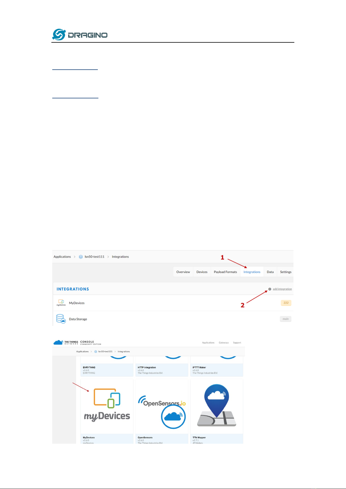
4.5 Integrate with Mydevice...........................................................................................................10
4.6 LEDs ..........................................................................................................................................12
4.7 Battery......................................................................................................................................12
5. Use AT Command.................................................................................................................... 13
5.1 Access AT Command.................................................................................................................13
6. FAQ ......................................................................................................................................... 14
6.1 How to upgrade the image?.....................................................................................................14
6.2 How to change the LoRa Frequency Bands/Region? ................................................................14
7. Order Info ...............................................................................................................................15
8. Packing Info ............................................................................................................................15
9. Support...................................................................................................................................15

www.dragino.com
LoRaWAN Door Sensor User Manual 3 / 15
1. Introduction
1.1 What is LDS01 LoRaWAN Door Sensor
The Dragino LDS01 is a LoRaWAN Door Sensor. It detects door open/close status and uplink to
LoRaWAN network. The LDS01 is small sensor; the dimension is as small as 64 x 30 x 14 mm.
LDS01 is powered by a CR2032 coin battery, in a good LoRaWAN Network Coverage case, it can
transmit as many as 12,000 uplink packets (base on SF7, 14dB). in poor LoRaWAN network
coverage, it can transmit ~ 1,300 uplink packets (base on SF10, 18dB). The design goal for one
battery is up to 1 year. User can easily change the CR2032 battery for reuse.
The LDS01 will send periodically data every day as well as for each door open/close action. It also
count the door open times and calculate last door open duration.
Each LDS01 is pre-loaded with a set of unique keys for LoRaWAN registrations, register these keys
to local LoRaWAN server and it will auto connect after power on.

www.dragino.com
LoRaWAN Door Sensor User Manual 4 / 15
1.2 Features
LoRaWAN Class A v1.0.3
Frequency Bands: CN470/EU433/KR920/US915/EU868/AS923/AU915/IN865/RU864
SX1262 LoRa Core
Door Open/Close detect
Door open/close statistics
CR2032 battery powered
AT Commands to change parameters
Uplink on periodically and open/close action
Remote configure parameters via LoRa Downlink
Firmware upgradable via program port
1.3 Applications
Smart Buildings & Home Automation
Logistics and Supply Chain Management
Smart Metering
Smart Agriculture
Smart Cities
Smart Factory
1.4 Dimension
1.5 Firmware Change log
LDS01 Image files –Download link
Image v1.0
Release

www.dragino.com
LoRaWAN Door Sensor User Manual 6 / 15
3. How to install LDS01

www.dragino.com
LoRaWAN Door Sensor User Manual 7 / 15
4. Operation Mode
4.1 How it works?
The LDS01 is configured as LoRaWAN OTAA Class A mode by default. It has OTAA keys to join
network. To connect a local LoRaWAN network, user just need to input the OTAA keys in the
network server and power on the LDS01. It will auto join the network via OTAA.
In case user can’t set the OTAA keys in the network server and has to use the existing keys from
server. User can use AT Command to set the keys in the devices.
4.2 Example to join LoRaWAN network
Here shows an example for how to join the TTN Network. Below is the network structure, we use
our LG308 as LoRaWAN gateway here.
The LDS01 in installed on the door edge to detect the open / close event. And send the status to
LoRaWAN server. The LDS01 will uplink two type of messages to the server.
A keep-alive message which send once per day.
A door event message when there is a door open/close.
The LG308 is already set to connect to TTN network . So what we need to now is only configure
the TTN:
Step 1: Create a device in TTN with the OTAA keys from LDS01.
Each LDS01 is shipped with a sticker with unique device EUI:

www.dragino.com
LoRaWAN Door Sensor User Manual 8 / 15
User can enter this key in their LoRaWAN Server portal. Below is TTN screen shot:
Add APP EUI in the application.
Add APP KEY and DEV EUI
Step 2: Power on LDS01 and it will auto join to the TTN network. After join success, it will start to
upload message to TTN and user can see in the panel.

www.dragino.com
LoRaWAN Door Sensor User Manual 9 / 15
4.3 Uplink Payload
Uplink Payload total 9 bytes.
Size(bytes)
2
1
3
3
value
Status&BAT
MOD
Always:0x01
Total open
door events
Last door open
duration (unit: min)
Example:
Example Payload Decoder in TTN:
http://www.dragino.com/downloads/index.php?dir=LoRa_End_Node/LDS01/Payload/
4.4 Downlink Payload
Downlink Control Type
Type Code
Downlink payload
size(bytes)
TDC (Transmit Time Interval—Keep Alive Interval)
0x01
4
RESET
0x04
2
Clear Counting
0xA6
2
Example Downlink payload setting in TTN:
Type Code 0x01

www.dragino.com
LoRaWAN Door Sensor User Manual 10 / 15
If the payload=0100003C, means to control the LDS01’s Keep Alive interval to 0x00003C=60(S)
Type Code 0x04
If payload = 0x04FF, it will reset the LDS01.
Type Code 0xA6
Example: 0xA601: Clear Counting
For LDS01: reset both count number and time.
4.5 Integrate with Mydevice
Mydevices provides a human friendly interface to show the sensor data, once we have data
in TTN, we can use Mydevices to connect to TTN and see the data in Mydevices. Below are
the steps:
Step 1: Be sure that your device is programmed and properly connected to the network at
this time.
Step 2: To configure the Application to forward data to Mydevices you will need to add
integration. To add the Mydevices integration, perform the following steps:

www.dragino.com
LoRaWAN Door Sensor User Manual 11 / 15
Step 3: Create an account or log in Mydevices.
Step 4: Search LDS01 and add DevEUI.

www.dragino.com
LoRaWAN Door Sensor User Manual 12 / 15
4.6 LEDs
Action
LED behavior
Power On
GREEN on 1s, RED on 1s, BLUE on 1s
Joined successful
GRENN LED on 5s
Send an uplink message
GREEN LED blinks once
Got a downlink message
BLUE LED blinks once
4.7 Battery
LDS01 is powered by a CR2032 coin battery, when running in deep sleep mode, the device power
consumption is ~5uA.
The main power consumption is transmitting an uplink message. Depends on LoRaWAN network
signal strength, the device can send different number of uplink messages.
1. In poor network coverage and US915 band. The device will transmit at SF10 at max power. in
this case, it can uplink about ~1,300 messages.
2. In good network coverage and EU868 band, the device will transmit at SF7, and can uplink as
many as 12,000 messages.
When battery voltage is below 2.75v, the LDS01 can’t send uplink message.
Note: It is recommended to change battery when it reaches 2.8v. After change the battery, make
sure to PRESS RESET button to active the low power mode.
Below shows the battery placement:

www.dragino.com
LoRaWAN Door Sensor User Manual 13 / 15
5. Use AT Command
5.1 Access AT Command
LDS01 supports AT Command set. User can use a USB to TTL adapter to configure LDS01 via use
AT command, as below.
USB to TTL <- -> LDS01
RX <- -> TX
TX <- -> RX
GND <- -> GND
In PC, User needs to set serial tool(such as putty, SecureCRT) baud rate to 115200 to access to
access serial console of LWL01. Below is the output for reference:
The AT Access password is 123456.
Each AT Command need to add an ENTER at the end before send.
When entering the first command, the RED LED will on and user can now input AT Commands.
After input all needed AT Commands, Please input AT+CLPM=1 to set the device to work in Low
Power mode and RED LED will be off.
More detail AT Command manual can be found at AT Command Manual

www.dragino.com
LoRaWAN Door Sensor User Manual 14 / 15
6. FAQ
6.1 How to upgrade the image?
User can upgrade the firmware of LWL01 for bug fix, new features, or change working region. The
upgrade instruction are here:
http://wiki.dragino.com/index.php?title=Firmware_Upgrade_Instruction
6.2 How to change the LoRa Frequency Bands/Region?
User can follow the introduction for how to upgrade image. When download the images, choose
the required image file for download.

www.dragino.com
LoRaWAN Door Sensor User Manual 15 / 15
7. Order Info
Part Number: LDS01-XXX
XXX:
EU433: frequency bands EU433
EU868: frequency bands EU868
KR920: frequency bands KR920
CN470: frequency bands CN470
AS923: frequency bands AS923
AU915: frequency bands AU915
US915: frequency bands US915
IN865: frequency bands IN865
CN779: frequency bands CN779
8. Packing Info
Package Includes:
LDS01 x 1
Dimension and weight:
Device Size: 64 x 30 x 14 mm
9. Support
Support is provided Monday to Friday, from 09:00 to 18:00 GMT+8. Due to different
timezones we cannot offer live support. However, your questions will be answered as soon
as possible in the before-mentioned schedule.
Provide as much information as possible regarding your enquiry (product models, accurately
describe your problem and steps to replicate it etc) and send a mail to
support@dragino.com
Table of contents
Other Dragino Accessories manuals

Dragino
Dragino N95S31B User manual

Dragino
Dragino CPL01 User manual

Dragino
Dragino LoRaWAN LDS02 User manual

Dragino
Dragino LHT65 User manual

Dragino
Dragino LSN50 LoRa User manual

Dragino
Dragino LSN50v2-D20 User manual

Dragino
Dragino LDDS04 User manual

Dragino
Dragino LWL02 User manual

Dragino
Dragino SW3L User manual

Dragino
Dragino LSE01 User manual