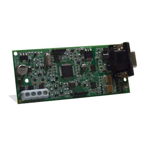
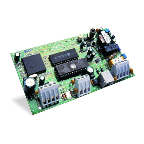
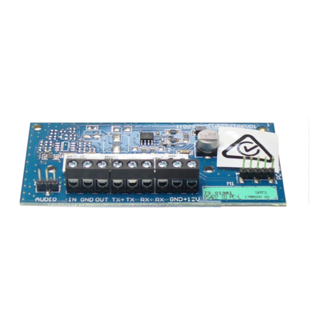
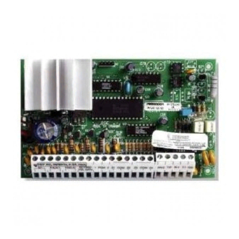
DSC MAXSYS PC4851 User manual

PC4851 v1.0 • Installation Manual
WARNING: This manual contains information
on limitations regarding product use and
function and information on the limitations
as to liability of the manufacturer. The entire
manual should be carefully read.
®
firealarmresources.com

WARNING Please Read Carefully
Note to Installers
This warning contains vital information. As the only individual in contact with system users, it is your responsibility to bring each item in
this warning to the attention of the users of this system.
System Failures
This system has been carefully designed to be as effective as possible. There are circumstances, however, involving fire, burglary, or other
types of emergencies where it may not provide protection. Any alarm system of any type may be compromised deliberately or may fail to
operate as expected for a variety of reasons
Limited Warranty
Digital Security Controls Ltd. warrants the original purchaser that for a period of twelve months from the date of purchase, the product
shall be free of defects in materials and workmanship under normal use. During the warranty period, Digital Security Controls Ltd. shall,
at its option, repair or replace any defective product upon return of the product to its factory, at no charge for labour and materials. Any
replacement and/or repaired parts are warranted for the remainder of the original warranty or ninety (90) days, whichever is longer. The
original owner must promptly notify Digital Security Controls Ltd. in writing that there is defect in material or workmanship, such writ-
ten notice to be received in all events prior to expiration of the warranty period.
International Warranty
The warranty for international customers is the same as for any customer within Canada and the United States, with the exception that
Digital Security Controls Ltd. shall not be responsible for any customs fees, taxes, or VAT that may be due.
Warrant y Proce dure
To obtain service under this warranty, please return the item(s) in question to the point of purchase. All authorized distributors and deal-
ers have a warranty program. Anyone returning goods to Digital Security Controls Ltd. must first obtain an authorization number. Digital
Security Controls Ltd. will not accept any shipment whatsoever for which prior authorization has not been obtained.
Conditions to Void Warranty
This warranty applies only to defects in parts and workmanship relating to normal use. It does not cover:
• damage incurred in shipping or handling;
• damage caused by disaster such as fire, flood, wind, earthquake or lightning;
• damage due to causes beyond the control of Digital Security Controls Ltd. such as excessive voltage, mechanical shock or water dam-
age;
• damage caused by unauthorized attachment, alterations, modifications or foreign objects;
• damage caused by peripherals (unless such peripherals were supplied by Digital Security Controls Ltd.);
• defects caused by failure to provide a suitable installation environment for the products;
• damage caused by use of the products for purposes other than those for which it was designed;
• damage from improper maintenance;
• damage arising out of any other abuse, mishandling or improper application of the products.
Digital Security Controls Ltd.’s liability for failure to repair the product under this warranty after a reasonable number of attempts will be
limited to a replacement of the product, as the exclusive remedy for breach of warranty. Under no circumstances shall Digital Security
Controls Ltd. be liable for any special, incidental, or consequential damages based upon breach of warranty, breach of contract, negli-
gence, strict liability, or any other legal theory. Such damages include, but are not limited to, loss of profits, loss of the product or any
associated equipment, cost of capital, cost of substitute or replacement equipment, facilities or services, down time, purchaser’s time, the
claims of third parties, including customers, and injury to property.
Disclaimer of Warranties
This warranty contains the entire warranty and shall be in lieu of any and all other warranties, whether expressed or implied
(including all implied warranties of merchantability or fitness for a particular purpose) And of all other obligations or liabilities
on the part of Digital Security Controls Ltd. Digital Security Controls Ltd. neither assumes nor authorizes any other person pur-
porting to act on its behalf to modify or to change this warranty, nor to assume for it any other warranty or liability concerning
this product.
This disclaimer of warranties and limited warranty are governed by the laws of the province of Ontario, Canada.
WARNING: Digital Security Controls Ltd. recommends that the entire system be completely tested on a regular basis. However, despite
frequent testing, and due to, but not limited to, criminal tampering or electrical disruption, it is possible for this product to fail to perform
as expected.
Installer’s Lockout
Any products returned to DSC which have the Installer’s Lockout option enabled and exhibit no other problems will be subject to a ser-
vice charge.
Out of Warranty Repairs
Digital Security Controls Ltd. will at its option repair or replace out-of-warranty products which are returned to its factory according to
the following conditions. Anyone returning goods to Digital Security Controls Ltd. must first obtain an authorization number. Digital
Security Controls Ltd. will not accept any shipment whatsoever for which prior authorization has not been obtained.
Products which Digital Security Controls Ltd. determines to be repairable will be repaired and returned. A set fee which Digital Security
Controls Ltd. has predetermined and which may be revised from time to time, will be charged for each unit repaired.
Products which Digital Security Controls Ltd. determines not to be repairable will be replaced by the nearest equivalent product available
at that time. The current market price of the replacement product will be charged for each replacement unit
firealarmresources.com

Introduction
The PC4851 ‘No Phone Bill’ module is used with the PC4850 Telephone Entry Controller to
eliminate the need for a dedicated telephone line. The PC4851 interfaces between the
tenant’s telephone and the existing telephone system, allowing communication between
the lobby intercom and the tenants. The PC4851 comprises a main controller board and
one or more 12 or 24 line relay cards to provide up to 750 telephone connections.
Operation
When a visitor calls a tenant the following will occur:
• The PC4851 rings the tenant’s telephone. If the phone is busy, the PC4851 module
sends a double beep, indicating that a visitor is calling from the lobby.
• The tenant can switch to the visitor’s call by pressing the Hook-switch or ‘3’ on their
telephone. This will disconnect the tenant’s telephone from the telephone system but
allow it to remain connected to the PC4851 module and the lobby intercom.
• The tenant can open doors by pressing 7for door #1 or 9for door #2.
• When the visitor’s call is finished, the tenant can return to the original call by pressing
Hook-switch or ‘3’ on their telephone.
1
Specifications
• Supply Voltage ........................................................................................24 VAC
• Supply Current.......................................................................................... 40VA
Parts List
Fig 1
Item No. Description Part Number
5
9
3
1,13
Not Shown
2
14
6
8
10/11
Not Shown
12
No Bill Module ......................................................................... PC4851
Relay Module ......................................................................... TAR301A
... Relay PCB (12 Lines) .............................................................. TC312
... Relay PCB (24 Lines) .............................................................. TC324
Interconnect Module ............................................................. TAB301A
Cabinet (2 Relay Mod Config.) ..............................................TCS6000S
Cabinet (10 Relay Mod Config.) ............................................ TCS6000L
Screws (4) ........................................................ #8, 1 1/2“ Wood Screw
Screws (2) .................................................. #6, 1/2“ Self Tapping Screw
2-Wire Phone Connector Cable...........................RJ-31 to 2 flying leads
Ground Wire...................................................................18 AWG (min)
4-Wire Phone Connector Cable ...............................RJ-31 to RJ-31 (4”)
24 VAC Power Source ..............................DSC PTD2440U or equivalent
Phone Panel Connector .............................................RJ-71C Connector
(Refer to Table 1 for wiring details)
firealarmresources.com

Telephone System Wiring
The PC4851 connects to the telephone system via one RJ-71C connector per 12 phone
lines (two for each fully populated relay board). These cables must be wired by the tele-
phone company prior to installation. Table 1 defines the cable wiring required by the
phone company. Ensure that the phone company provides the Line Number and Apt.
Number information required in Table 2. This will enable management to assign directory
codes correctly.
2
Table 1 RJ-71C Cable Connections
Line No Function
Outgoing Lines
To Tenant Phones
Incoming Lines
From Phone Co.
Color Contact Color Contact
1Tip
Ring
Blue/White
Orange/White
1
2
White/Blue
White/Orange
26
27
2Tip
Ring
Green/White
Brown/White
3
4
White/Green
White/Brown
28
29
3Tip
Ring
Slate/White
Blue/Red
5
6
White/Slate
Red/Blue
30
31
4Tip
Ring
Orange/Red
Green/Red
7
8
Red/Orange
Red/Green
32
33
5Tip
Ring
Brown/Red
Slate/Red
9
10
Red/Brown
Red/Slate
34
35
6Tip
Ring
Blue/Black
Orange/Black
11
12
Black/Blue
Black/Orange
36
37
7Tip
Ring
Green/Black
Brown/Black
13
14
Black/Green
Black/Brown
38
39
8Tip
Ring
Slate/Black
Blue/Yellow
15
16
Black/Slate
Yellow/Blue
40
41
9Tip
Ring
Orange/Yellow
Green/Yellow
17
18
Yellow/Orange
Yellow/Green
42
43
10 Tip
Ring
Brown/Yellow
Slate/Yellow
19
20
Yellow/Brown
Yellow/Slate
44
45
11 Tip
Ring
Blue/Purple
Orange/Purple
21
22
Purple/Blue
Purple/Orange
46
47
12 Tip
Ring
Green/Purple
Brown/Purple
23
24
Purple/Green
Purple/Brown
48
49
Not Connected Slate/Purple 25 Purple/Slate 50
firealarmresources.com

Installation (Refer to Figure 1 PC4851 Installation)
1. Locate the cabinet (1) in a dry area, close to the RJ-71C telephone block, with access
to an unswitched AC power source. Mount the panel using appropriate wall anchors
for the intended surface with 4 screws (2).
2. Install the plastic card guides (4) if required.
3. Insert the PC4851 module (5) through the card guides into the interconnect board (3).
Ensure that the board locks in place.
4. Connect the two-wire connector cable (6) from NB1 and NB2 of the PC4850 control-
ler into J1 of the PC4851 module.
5. Connect 24 VAC to terminals 1 and 2 (7) of the PC4851 module
WARNING: Do NOT apply power until all wiring is completed.
6. Connect the ground wire lead (8) to terminal 3 of the PC4851 module.
WARNING: Connect ground wire to chassis of AC outlet box.
7. Insert the relay modules (9) as described in Step 3.
8. Connect the short 4-conductor cable (10) from J2 on the PC4851 module to J1 on the
adjacent relay board.
NOTE: If more than one relay module is used, connect J2 (11) of the first relay
module to J1 of the second relay module. Connect additional relay modules in the
same manner.
9. Verify that the all wiring is correct and that connections are secure before connecting
RJ-71C interface cables to CON 1 and CON 2 on the relay modules.
10. Position cover (13) at bottom of cabinet. Slide cover upwards until flush with cabinet,
secure with the two screws (14) provided.
Programming
Enter the following at the MAXSYS system keypad; Refer to PC4020 Installation Manual.
1. Enter [*][8][Installer’s Code].
2. Enter reference number [0017XX00] where XX is the number of the PC4850 module
3. Use the arrow (<>) keys to scroll until No Bill is displayed
4. Press [*] to toggle the option ON.
5. Press [#] 4 times to finish.
Testing
• Verify correct operation by manually entering each directory code and verifying the
apartment number.
• Record all information in the Block Identification Form (Table 2) for reference.
3
firealarmresources.com

4 5
firealarmresources.com

Table 2 RJ-71C Block Identification Form
6
RJ-71C Block Number
Directory
Code
Apt.
Number
Line
Number
RJ-71C Pins
Output
27,28
29,30
31,32
33,34
35,36
37,38
39,40
41,42
43,44
45,46
47,48
49,50
Input
1,2
3,4
5,6
7,8
9,10
11,12
13,14
15,16
17,18
19,20
21,22
23,24
Relay
Line No.
1
2
3
4
5
6
7
8
9
10
11
12
RJ-71C Block Number
Directory
Code
Apt.
Number
Line
Number
RJ-71C Pins
Output
27,28
29,30
31,32
33,34
35,36
37,38
39,40
41,42
43,44
45,46
47,48
49,50
Input
1,2
3,4
5,6
7,8
9,10
11,12
13,14
15,16
17,18
19,20
21,22
23,24
Relay
Line No.
1
2
3
4
5
6
7
8
9
10
11
12
firealarmresources.com

7
RJ-71C Block Number
Directory
Code
Apt.
Number
Line
Number
RJ-71C Pins
Output
27,28
29,30
31,32
33,34
35,36
37,38
39,40
41,42
43,44
45,46
47,48
49,50
Input
1,2
3,4
5,6
7,8
9,10
11,12
13,14
15,16
17,18
19,20
21,22
23,24
Relay
Line No.
1
2
3
4
5
6
7
8
9
10
11
12
RJ-71C Block Number
Directory
Code
Apt.
Number
Line
Number
RJ-71C Pins
Output
27,28
29,30
31,32
33,34
35,36
37,38
39,40
41,42
43,44
45,46
47,48
49,50
Input
1,2
3,4
5,6
7,8
9,10
11,12
13,14
15,16
17,18
19,20
21,22
23,24
Relay
Line No.
1
2
3
4
5
6
7
8
9
10
11
12
firealarmresources.com

INDUSTRY CANADA STATEMENT
AV I S : L’étiquette de l’Industrie Canada identifie le matériel homologué. Cette étiquette certifie
que le matériel est conforme à certaines normes de protection, d’exploitation et de sécurité des
réseaux de télécommunications. Industrie Canada n’assure toutefois pas que le matériel fonction-
nera à la satisfaction de l’utilisateur.
Avant d’installer ce matériel, l’utilisateur doit s’assurer qu’il est permis de le raccorder aux instal-
lations de l’entreprise locale de télécommunication. Le matériel doit également être installé en
suivant une méthode acceptée de raccordement. L’abonné ne doit pas oublier qu’il est possible
que la conformité aux conditions énoncées ci-dessus n’empêchent pas la dégradation du service
dans certaines situations.
Les réparations de matériel homologué doivent être effectuées par un centre d’entretien canadien
autorisé désigné par le fournisseur. La compagnie de télécommunications peut demander à l’util-
isateur de débrancher un appareil à la suite de réparations ou de modifications effectuées par
l’utilisateur ou à cause de mauvais fonctionnement.
Pour sa propre protection, l’utilisateur doit s’assurer que tous les fils de mise à la terre de la source
d’énergie électrique, les lignes téléphoniques et les canalisations d’eau métalliques, s’il y en a, sont
raccordés ensemble. Cette précaution est particulièrement importante dans les régions rurales.
AVERTISSEMENT: L’utilisateur ne doit pas tenter de faire ces raccordements lui-même; il doit
avoir recours à un service d’inspection des installations électriques, ou à un électricien, selon le
cas.
Indice d’équivalence de la sonnerie (IÉS) assigné a chaque dispositif terminal indique, pour éviter
toute surcharge, le pourcentage de la charge totale qui peut être raccordée à un circuit télépho-
nique bouclé utilisé par ce dispositif. La terminaison du circuit bouclé peut être constituée de
n’importe quelle combinaison de dispositifs, pourvu que la somme des indices d’équivalence de la
sonnerie de l’ensemble des dispositifs ne dépasse pas 5.
Indice d’équivalence de la sonnerie de ce produit est 0.0.
NOTICE: The Industry Canada label identifies certified equipment. This certification means that
the equipment meets certain telecommunications network protective, operational and safety
requirements. Industry Canada does not guarantee the equipment will operate to the user’s satis-
faction.
Before installing this equipment, users should ensure that it is permissible to be connected to the
facilities of the local telecommunications company. The equipment must also be installed using an
acceptable method of connection. The customer should be aware that compliance with the above
conditions may not prevent degradation of service in some situations.
Repairs to certified equipment should be made by an authorized Canadian maintenance facility
designated by the supplier. Any repairs or alterations made by the user to this equipment, or
equipment malfunctions, may give the telecommunications company cause to request the user to
disconnect the equipment.
User should ensure for their own protection that the electrical ground connections of the power
utility, telephone lines and internal metallic water pipe system, if present, are connected together.
This precaution may be particularly important in rural areas.
CAUTION: Users should not attempt to make such connections themselves, but should contact
the appropriate electric inspection authority, or electrician, as appropriate.
The Ringer Equivalence Number (REN) assigned to each terminal device denotes the percentage
of the total load to be connected to a telephone loop which is used by the device, to prevent over-
loading. The termination on a loop may consist of any combination of devices subject only to the
requirement that the total of the Ringer Equivalence Number of all the devices does not exceed 5.
The Ringer Equivalence number of this unit is 0.0.
8
firealarmresources.com

FCC COMPLIANCE STATEMENT
CAUTION: Changes or modifications not expressly approved by Digital Security Controls Ltd. could void your
authority to use this equipment.
This equipment has been tested and found to comply with the limits for a Class B digital device, pursuant to Part
15 of the FCC Rules. These limits are designed to provide reasonable protection against harmful interference in a
residential installation. This equipment generates, uses and can radiate radio frequency energy and, if not
installed and used in accordance with the instructions, may cause harmful interference to radio communica-
tions. However, there is no guarantee that interference will not occur in a particular installation. If this equip-
ment does cause harmful interference to radio or television reception, which can be determined by turning the
equipment off and on, the user is encouraged to try to correct the interference by one or more of the following
measures:
• Re-orient the receiving antenna.
• Increase the separation between the equipment and receiver.
• Connect the equipment into an outlet on a circuit different from that to which the receiver is connected.
• Consult the dealer or an experienced radio/television technician for help.
The user may find the following booklet prepared by the FCC useful: “How to Identify and Resolve Radio/Tele-
vision Interference Problems”. This booklet is available from the U.S. Government Printing Office, Washington
D.C. 20402, Stock # 004-000-00345-4.
Important Information
This equipment complies with Part 68 of the FCC Rules. On the side of this equipment is a label that contains,
among other information, the FCC registration number of this equipment.
NOTIFICATION TO TELEPHONE COMPANY.The customer shall notify the telephone company of the particular line
to which the connection will be made, and provide the FCC registration number and the ringer equivalence of the
protective circuit.
FCC Registration Number: F53CAN-36295-AL-N
Ringer Equivalence Number: 0.0
USOC Jack: RJ-71C
T
ELEPHONE CONNECTION REQUIREMENTS.Except for the telephone company provided ringers, all connections
to the telephone network shall be made through standard plugs and telephone company provided jacks, or
equivalent, in such a manner as to allow for easy, immediate disconnection of the terminal equipment. Standard
jacks shall be so arranged that, if the plug connected thereto is withdrawn, no interference to the operation of the
equipment at the customer’s premises which remains connected to the telephone network shall occur by reason
of such withdrawal.
INCIDENCE OF HARM.Should terminal equipment or protective circuitry cause harm to the telephone network,
the telephone company shall, where practicable, notify the customer that temporary disconnection of service
may be required; however, where prior notice is not practicable, the telephone company may temporarily dis-
continue service if such action is deemed reasonable in the circumstances. In the case of such temporary discon-
tinuance, the telephone company shall promptly notify the customer and will be given the opportunity to
correct the situation.
ADDITIONAL TELEPHONE COMPANY INFORMATION.The security control panel must be properly connected to the
telephone line with a USOC RJ-71C telephone jack.
The FCC prohibits customer-provided terminal equipment from being connected to party lines or being used in
conjunction with coin telephone service. Interconnect rules may vary from state to state.
CHANGES IN TELEPHONE COMPANY EQUIPMENT OR FACILITIES.The telephone company may make changes in its
communications facilities, equipment, operations or procedures, where such actions are reasonably required and
proper in its business. Should any such changes render the customer’s terminal equipment incompatible with
the telephone company facilities the customer shall be given adequate notice to effect the modifications to main-
tain uninterrupted service.
RINGER EQUIVALENCE NUMBER (REN). The REN is useful for determining the number of devices that you may
connect to your telephone line and still have all of those devices ring when your telephone number is called. In
most, but not all areas, the sum of the RENs of all devices connected to one line should not exceed five (5.0). To
be certain of the number of devices that you may connect to your line, you may want to contact your local tele-
phone company.
EQUIPMENT MAINTENANCE FACILITY.If you experience trouble with this telephone equipment, please contact
your equipment supplier for information on obtaining service or repairs. The telephone company may ask that
you disconnect this equipment from the network until the problem has been corrected or until you are sure that
the equipment is not malfunctioning.
firealarmresources.com

©2001 Digital Security Controls Ltd., Toronto, Canada
www.dsc.com
1-800-387-3630
Printed in Canada 29005803 R001
firealarmresources.com
Table of contents
Other DSC Control Unit manuals

DSC
DSC PC6216 User manual

DSC
DSC PCL422 User manual

DSC
DSC Maxsys PC4116 User manual

DSC
DSC Maxsys PC4937 User manual

DSC
DSC PowerSeries PC585 User manual

DSC
DSC PC5720 User manual

DSC
DSC AMP-704 User manual

DSC
DSC Power Series PC5904 User manual

DSC
DSC Downlook DLM-7 User manual

DSC
DSC PowerSeries Neo V1.2 User manual

DSC
DSC Sur-Gard DVACS PC54OO User manual

DSC
DSC PC5400 User manual

DSC
DSC Misterhouse PC5401 User manual

DSC
DSC MAXSYS PC4850 User manual

DSC
DSC Maxsys PC4701 User manual

DSC
DSC IT-100 User manual

DSC
DSC PC5928 User manual

DSC
DSC ESCORT558OTC User manual

DSC
DSC Misterhouse PC5401 User manual

DSC
DSC PC6216 User manual