manuals.online logo
Brands
  1. Home
  2. •
  3. Brands
  4. •
  5. Takex
  6. •
  7. Security Sensor
  8. •
  9. Takex PA-6614E User manual

Takex PA-6614E User manual

①

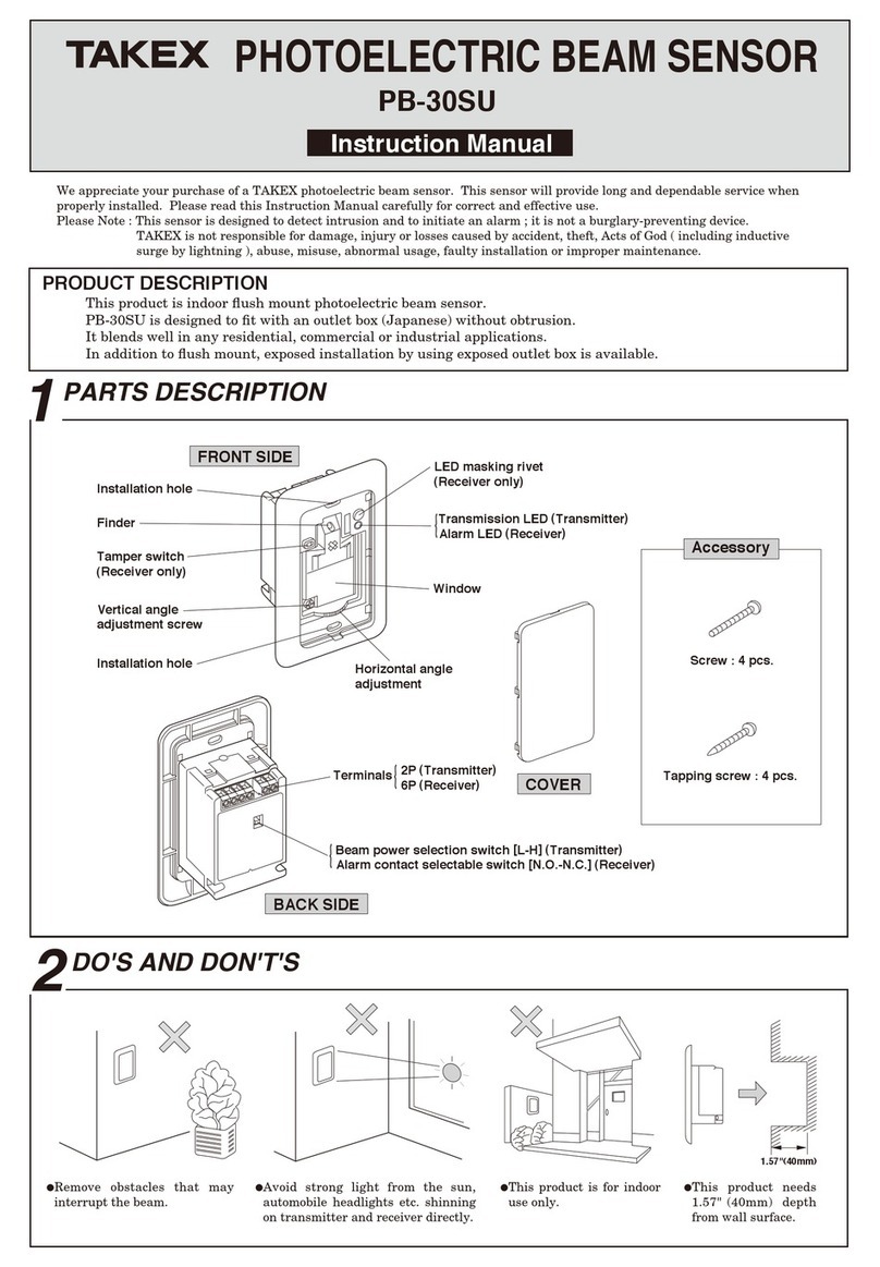
3$576'(6&5,37,21
352'8&7'(6&5,37,21
Wire lead
(For exposed wiring)
Wire lead
(Knockout) Wiring hole Locking screw hole Release lever
Terminals
Front mark
Wiring hole
Memory LED
(inside) : Yellow
Alarm LED
(inside) : Red
【SENSOR UNIT】Range setting selector
Function selector
Indicator
Area setting chart Area setting selector
Function setting
Front mark
'26$1''2176
●Install the sensor in a location where
intruders are more likely to cross the
protection zones, rather than approach
head on.
●
Do not install in a location which is
subject to electrical noise or
intense vibration.
●Avoid direct sunlight, spot light or
intense reflections on the sensor or
the protection zone.
●Do not install the sensor outdoors
(indoor only).
[MAINTENANCE]
1.When the unit is soiled, clean the cover with a soft cloth moistened with a small
amount of cleansing -solution.
Do not use chemicals such as thinners or alcohol.
2.Check operation once a week.
Do not fail to check operation whenever furniture in coverage area is moved.
●
The passive infrared sensor is designed to detect infrared energy variations
caused by the presence of a human body.
Therefore, note that similar variations in conditions in protection area, due
to other reasons, may cause the sensor to create an alarm as it is unable
to distinguish between sources.

&29(5$*(
ʄ:LGH DQJOH SURWHFWLRQ
Topview
●

Instruction Manual
Wide angle protection : PA-6614E ・PA-6614E(BL):Black color
TWIN MIRROR
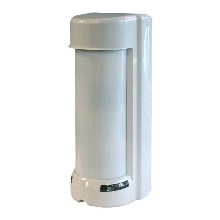
PASSIVE INFRARED SENSOR
We appreciate your purchase of a TAKEX passive infrared sensor. This sensor will provide long and dependable service when
properly installed. Please read this Instruction Manual carefully for correct and effective use.
Please Note : This sensor is designed to detect intrusion and to initiate an alarm ; it is not a burglary-preventing device.
TAKEX is not responsible for damage, injury or losses caused by accident, theft, Acts of God ( including inductive
surge by lightning ), abuse, misuse, abnormal usage, faulty installation or improper maintenance.
・
PA-6614E is a passive infrared sensor that detects far-infrared energy emitted from the human body and outputs an alarm signal.
・A new detection system that combines the twin mirror system and the second generation fuzzy processing improve a detection
  
 
performance and reduce a false detection by small animals, and stable operation is possible in wide range of installation locations.
・Detection distance up to 14m(46')
・Mounting height up to 6m(19') in "High density mode" (*Max 5m(16') in "Standard mode")
・Lower current consumption makes it possible to use a power supply with a smaller capacity than before.
【BASE UNIT】
1.9
1.8
0.6
0.8
0
8°
Variablerange
Sideview
●
2.5m
57.9°
6.8°
14m
10
5
0
23.4°
indicator【B】
②
,167$//$7,21
:,5,1*
(1) Slide release lever to a direction
that an arrow points to detach
sensor unit from base unit.
(2)
Mount the base on the ceiling with screws. Fix so
that the front mark ( ) is pointing to the center of
protection area.
*
Break knockout and put the wire through wire
  
lead on base unit, when exposed wiring.
(3)
(4)
(5)
Match up a front mark on base unit with that on
sensor unit. Put a sensor unit into a base unit
from front mark side.
Push sensor unit until release lever will click.
Sensor locking screw
【Basic connection】
>:KHQWZRXQLWVDUHXVHG@
【
Allowable wiring distance between sensor and power source
】
6L]HRIZLUHXVHG
$:*
$:*
$:*
'LVWDQFHDW9'&
PIW
PIW
PIW
  
3RZHU
}
6LJQDO
LQSXW
+
ー
6HQVRU1&
1
23
4 1
23
4
6HQVRU1&
(6)
When sensor unit is detached, hold it
and slide release lever as illustrated.
(7)
When sensor unit is locked, tighten
the locking screw.
Release lever
【Terminal arrangement】
123 4
$ODUPRXWSXW
'U\FRQWDFW6HPL&RQGXFWRU
1&12VHOHFWDEOH
5HVHWDSSUR[VHF
9$&'&$
3URWHFWLYHUHVLVWRUї
3RZHUQRQSRODULW\
9WR9'&
P$RUOHVV
7DPSHU
1&
9$&'&
$
6
5



Please set "1. Detection area" and "2. Operation mode" 
properly according to the installation conditions (ceiling height and Max. detection distance)
and operation conditions.
Set the “Area setting selector” and “Range setting selector” based on "Area setting chart" as a guide.
Alphabet “A” to “J” appears in the "Indicator” by moving the area setting selector up and down.
Select the alphabet based on detection area condition.
Select "Range ①"or "Range ②" according to the color of selected alphabet from "Area setting chart".
*Gray color : Range ①, White color : Range ②in the Area setting chart.
2.Operation mode setting
Select "Operation mode" with Dip switch 6 and 7 in function selector based on operating condition.
6WDQGDUGPRGH
【1】【2】【3】Set "【1】, 【2】, 【3】
" according to the selected alphabet in above "Detection area setting".
+LJKGHQVLW\PRGH
This mode detects even small movements of the human body and can be operated over a wide range beyond the
standard mode setting range.
*
When operating in this mode, set the Range setting selector to “White color” regardless of the installation conditions.
30
8
$5($$'-8670(17$1'23(5$7,2102'(6(77,1*
Note
1) The maximum wire length, when two or more units are connected, is the
above distance divided by the number of units.
2) The protection circuit can be wired to a distance of 2,900m (9,500 ft.) with
AWG 22 wire.
*Wait approx. one minute for warm-up after power is applied. (Alarm LED is
flashing) In the meantime, an alarm is not initiated.
*After the one minute has passed the unit will be in the armed condition and will
trigger the alarm when detecting a human body.
1.Detection area setting
Area setting selector
Range setting selector
Connect the wires to the terminals referring
to the paragraph on “6.WIRING”.
Set the protection area referring to the
paragraph on “7.AREA ADJUSTMENT AND
OPERATION MODE SETTING”.
③
)81&7,216(77,1*
23(5$7,21&+(&.

The area setting chart displayed on the back of the sensor unit is
for"Standard mode".
For the high density mode, refer to the area set chart of
"High density mode" at the right and set the indicator.
Note
$UHDVHWWLQJFKDUW
µ6WDQGDUGPRGHµ
5DQJHVHWWLQJVHOHFWRU
([+HLJKWPIW0D[GLVWDQFHPIW
Area setting chart "Standard mode"
A
C
ON
OFF
ON
N.O.
OFF
N.C.
ON
OFF
3警報接点
23(5$7,2102'(
ON
OFF
ON
OFF
ON
OFF
ON
OFF
ON
OFF
120% 100% 80% 60%
ON
OFF
1234567
8
ON
OFF
2873877,0(
①
②
A
'2:1
83
B
OUTPUTTIME
5min
①
②
J
H
ON
OFF
67
①
②
B
ON
OFF
67
①
②
G
EF
ON
OFF
67
I
2.5m
14m1050
6m
0 5 10 12m
3.5m
058m

(1) Turn the power ON, and wait 1 minute until the alarm LED stops flashing.
(2) Walk test in the protection area to check if an alarm is activated. Check on both of the alarm LED and control panel.
(3) After correct operation has been confirmed, turn the alarm LED OFF with mode selector on the
back of sensor unit. (When set at OFF, the alarm LED does not light even if an alarm is activated.)
Memory is always stored when sensor is armed.
When an alarm has been activated, the memory
LED flashes for 3 min. and then remains lit for 47 min.
It automatically reset and memory is also canceled.
$/$50&217$&7
(4)SENSITIVITY
Switch4,5
Operation :
$/$500(025<
Switch2
Switch1
Factoryset
)XQFWLRQVHOHFWRU
$/$50/('
ON : Lights at alarm
OFF : LED off
Auto-reset
Memory MemoryOFF
Factoryset
Switch3
Factoryset
Factoryset
ON
OFF
N.O.
N.C.
120
100
80
60
ON
OFF
1 LED 2
MEMORY
3
ALARM
4,5 SENS.(%) 6,7 OPERATIONMODE 8
OUTPUTTIME

)81&7,216(77,1*
【1】
【2】
Highdensity
 【3】 5min
2sec
Highdensity
【1】 【2】 【3】
OUTPUTTIME
2sec
Switch8
Switch6,7
【Back side of sensor unit】
5DQJHVHWWLQJVHOHFWRU
,QGLFDWRU
$UHDVHWWLQJVHOHFWRU
*UD\FRORU :①
:KLWHFRORU:②
:KLWHFRORU
:KLWHFRORU
([+HLJKWPIW0D[GLVWDQFHPIW
$UHDVHWWLQJFKDUW%*UD\0RGH【3】
 
5DQJHVHWWLQJVHOHFWRU
,QGLFDWRU
$UHDVHWWLQJ
VHOHFWRU
2SHUDWLRQPRGH
$UHDVHWWLQJFKDUW):KLWH0RGH【

】
Note
5DQJHVHWWLQJVHOHFWRU
,QGLFDWRU
$UHDVHWWLQJ
VHOHFWRU
2SHUDWLRQPRGH
[
For horizontal adjustment
] Make use of mounting hole of base. (25° adjustable)
 
)XQFWLRQVHOHFWRU'LSVZLWFK2SHUDWLRQPRGH
Area setting chart "High density mode"
HIGHDENSITY
In case High density

mode, select Range

▷White" in all setting .
([+HLJKWPIW0D[GLVWDQFHPIW
$UHDVHWWLQJFKDUW,:KLWH+LJKGHQVLW\PRGH
5DQJHVHWWLQJVHOHFWRU2SHUDWLRQPRGH
,QGLFDWRU
$UHDVHWWLQJ
VHOHFWRU
Note
Set according to the area setting
chart for stable detection
performance.
Use this setting when the ceiling is high and beyond standard operation, or when you want to
detect sensitively even small movements of the human body.
By selecting this mode, small animal identification performance and stability against
temperature changes will be lower than other settings.
+LJKGHQVLW\PRGH
6WDQGDUGPRGH
【】【】【】
ON : 5 min latch time after detection
OFF : 2 sec (one shot ) after detection
Factorysetting
Otherfunctions
Self-diagnosis function :
Temperature compensate :
Factoryset
Factoryset
【】
【】
*UD\FRORU
+LJK
GHQVLW\
ON : N.O.
OFF : N.C.
DISTANCE
HEIGHT
(m)
(m)
(ft )
2.0
2.5
3.0
3.5
43 5 6 7 8 9 10 11 12 13
4.0
5.0
6.5
8.5
10
12
13
16
A
B
C
C
B
C
A
C
E
14
33 36 40 42 46
16.5
2010 13 23 26
29.5
C
C
D
I
D
G
I
HG
A
BH
GF
H
GC
D
J
E
G
H
D
E
F
H
I
E
F
I
G
I
C
B
D
E
G
I
B
C
C
D
E
H
B
C
D
E
F
H
B
D
E
F
G
I
MODE
6.0
20
JJJ
DISTANCE
HEIGHT
(m)
(m)
(ft)
2.0
2.5
3.0
3.5
43 5 6 7 8 9 10 11 12 13
4.0
5.0
6.5
8.5
10
12
13
16
A
B
C
C
B
C
A
C
E
14
33 36 40 42 46
16.5
2010 13 23 26
29.5
C
C
A
BH
GF
H
GC
D
J
E
G
H
D
E
F
H
I
E
F
I
G
I
C
B
D
E
G
I
B
C
C
D
E
H
B
C
D
E
F
H
B
D
E
F
G
I
MODE
To set the appropriate detection area, adjust “Area setting selector/ Range
setting selector /Function selector” appropriately according to the “Area
setting chart”. Inappropriate selection may reduce performance of human body
detection and small animal identification.
In High-density mode, the sensor detects small
movements of the human body, and the small animal
identification performance becomes lower than the
standard mode.
【1】 【2】 【3】
Sensor operation can be adjusted by Function
selector on the back of unit to suit its application /
environment.
The sensor unit detects a failure of pyroelectric element or a
disconnection inside and continuously notifies it as a failure alarm.
This function stabilizes the detection performance by measuring the
ambient temperature of the sensor.
④No.06-073
C0055
,Q-DSDQ
Takex America Inc.Takenaka Engineering Co., Ltd.
KWWSVZZZWDNH[HQJFRMS
Takex America Inc.
KWWSVZZZWDNH[FRP
Takex Europe Ltd.
KWWSVZZZWDNH[FRP
,QWKH86 ,QWKH8.
,Q$XVWUDOLD
$YLDU\&RXUW:DGH5RDG
%DVLQJVWRNH+DPSVKLUH5*3(8.
7HO
)D[
+RZOH\V5RDG1RWWLQJ+LOO
9,&
7HO
)D[
KWWSVZZZWDNH[FRP
*RMR'RUL6RWRNDQ1LVKLLUX+LJDVKLQR
<DPDVKLQDNX.\RWR-DSDQ
7HO
)D[
6DQ=HQR:$<
6XQQ\YDOH&$86$
7HO
)D[
Limited Warranty :
TAKEX products are warranted to be free from defects in material and workmanship for 12 months from original date of shipment. Our warranty does not cover damage or
failure caused by Acts of God (including inductive surge by lightning), abuse, misuse, abnormal usage, faulty installation, improper maintenance or any repairs other than
those provided by TAKEX. All implied warranties with respect to TAKEX, including implied warranties for merchantability and implied warranties for fitness, are limited in
duration to 12 months from original date of shipment. During the Warranty Period, TAKEX will repair or replace, at its sole option, free of charge, any defective parts
returned prepaid. Please provide the model number of the products, original date of shipment and nature of difficulty being experienced. There will be charges rendered for
product repairs made after our Warranty period has expired.
■OPTION:BL-5000
:BCW-401
:BP-150AE
7528%/(6+227,1*
  (;7(51$/',0(16,216

63(&,),&$7,216
Solve possible problems according to the following table. If normal operations cannot be
restored by this means, contact either the dealer from whom you bought the unit or TAKEX.
Completely inactive
Sometimes inactive
(1)No power supply, broken wire or improper voltage.
(2)
Not yet 1 minute after power turned on (Alarm LED is flickering.)
(3)Cover shielded by substances (including glass).
(4)Improper area adjustment.
(1)Improper area adjustment.
(2)Cover face is soiled with dust or water drop.
(3)Is the protection range proper ?
(4)Small temperature difference between people and back ground.
(1)Something moving in protected area or too rapid temperature variations.
(3)
Intense reflection of sun light or head light shining on the sensor.
(4)Is the sensor reacting to passersby outside ?
(1)Poor contact output connection or broken wire or short circuit.
(2)Contact output is not working.
(3)Is the connected unit operation nomal ?
(1)Correct power supply or replace broken wire.
(2)Allow for warming up time (about 1 min.)
(3)Remove the substances.
(4)Readjust the protection area setting.
(1)Readjust the protection area setting.
(3)Reposition so that the range is proper.
(4)Set sensitivity 120%
(1)Remove the cause.
(2)Relocate device.
(3)Relocate device. Shield with a blind.
(4)Readjust the protection area.
(1)Check the wiring or connection.
(1)Check for disconnection or damage inside the device.
(2)Check the contact output terminal using a tester.
(3)Check the connected unit.
Mounting position
Ambient temperature range
Memory LED
Sensitive zone
Supply voltage
Coverage
Detection system
Model
Tapping screw : 2 pcs. Sensor locking screw : 1 pce.
PA-6614E PA-6614E(BL)
The specifications are subject to change without notice.
(2)Clean the cover with soft cloth.
(Do not use chemicals such as thinners or alcohol.)
Activated when no person
has passed
The alarm LED lights, but
connected units are inactive
(2)Large electrical noise source such as power machine nearby or
its wiring close to that of sensor.
Trouble Check CorrectiveAction
Passive infrared (Twin mirror)
Wide angle 14m Max.
8mA Max.
38 pairs
7 to 30V DC (non-polarity)
Dry contact (Semi-Conductor)
(N.C. / N.O. selectable)
Reset : Approx. 2 sec., 24V (AC/DC) 0.25A
(protective resistor 3.3Ω)
3 minutes flashing, 47 minutes lighting and
automatically reset. (ON/OFF selectable)
Red : Flashing at warming up
Lighting at alarm (LED can be disabled)
Yellow : Flashing at memory activated
Lighting at memory indication
Vertically : 23°
Horizontally : 25° (on mounting hole of base)
60% / 80% / 100% / 120% changeover
-15℃ to +55℃(+5° F to +131° F)
without condensation
Indoor ceiling
(wall mount with optional attachment BCW-401)
Accessory
Terminals on separate base unit
120g (4.23oz)
Body /Cover : White resin Body /Cover : Black resin
Protection
Sensorunit
Baseunit
φ120mm(φ4.72")
▲
▲
▲
▲
▲
▲
▲
▲
Wirehole
▲
▲
▲
▲
▲
▲
▲
▲
▲
▲
▲
▲
▲
▲
▲
▲
▲
▲
▲
▲
35゜
35
゜
35゜
35
°
R15mm
(R0.59")
Releaselever
Locking
screwhole
φ98.5mm(φ3.88")
55mm(2.17")
8mm(0.31")
φ83.5mm(φ3.29")
66.7mm(2.60")
5-φ4.2mm
(φ0.17")
φ9mm
(φ0.35")
4.2mm(0.17")
34mm
(1.34")
10.5mm
(0.41")
The alarm LED lights and
alarm signal output
continuously
(1)Self-diagnosis error.
Current consumption
Alarm signal
Alarm memory
Alarm LED
Adjustment
Sensitivity changeover
Self-diagnosis function
Temperature compensate
Other functions
N.C. 30V(AC/DC)0.25A
Wiring connection
Weight
Appearance
Tamper
This manual suits for next models

1

Other Takex Security Sensor manuals

Takex PIR-T45WP User manual

Takex

Takex PIR-T45WP User manual

Takex PR-5B User manual

Takex

Takex PR-5B User manual

Takex TXF-125-KH User manual

Takex

Takex TXF-125-KH User manual

Takex SSP-S200 Series User manual

Takex

Takex SSP-S200 Series User manual

Takex FP-5500E User manual

Takex

Takex FP-5500E User manual

Takex Quad PB-IN-50HF User manual

Takex

Takex Quad PB-IN-50HF User manual

Takex MS-100E User manual

Takex

Takex MS-100E User manual

Takex PA-5312E User manual

Takex

Takex PA-5312E User manual

Takex PA-6812E User manual

Takex

Takex PA-6812E User manual

Takex MX-12FAMD User manual

Takex

Takex MX-12FAMD User manual

Takex PB-30SU User manual

Takex

Takex PB-30SU User manual

Takex MX-12FAM User manual

Takex

Takex MX-12FAM User manual

Takex PIR-T15WE(W) User manual

Takex

Takex PIR-T15WE(W) User manual

Takex MS-12 Series User manual

Takex

Takex MS-12 Series User manual

Takex PB-100AT-KH User manual

Takex

Takex PB-100AT-KH User manual

Takex Quad PB-IN-50HF User manual

Takex

Takex Quad PB-IN-50HF User manual

Takex GS-2000E User manual

Takex

Takex GS-2000E User manual

Takex PXB-100ATC-KH User manual

Takex

Takex PXB-100ATC-KH User manual

Takex PXB-100SW User manual

Takex

Takex PXB-100SW User manual

Popular Security Sensor manuals by other brands

RKI Instruments 35-3001-01H Operator's manual

RKI Instruments

RKI Instruments 35-3001-01H Operator's manual

Bosch Blue Line D1-P quick start guide

Bosch

Bosch Blue Line D1-P quick start guide

Viking LDB-2 product manual

Viking

Viking LDB-2 product manual

SIUI CTS-9006 Operation manual

SIUI

SIUI CTS-9006 Operation manual

BEA WIZARD II SMR user guide

BEA

BEA WIZARD II SMR user guide

bolid S2000-IK Rev.03 instruction manual

bolid

bolid S2000-IK Rev.03 instruction manual

Agilent Technologies G1314B user manual

Agilent Technologies

Agilent Technologies G1314B user manual

DSC LC-100-PI installation manual

DSC

DSC LC-100-PI installation manual

Visonic NEXT DUO installation instructions

Visonic

Visonic NEXT DUO installation instructions

WITTUR USG-25P operating instructions

WITTUR

WITTUR USG-25P operating instructions

showhome ZW112 manual

showhome

showhome ZW112 manual

Robertshaw 365A instruction manual

Robertshaw

Robertshaw 365A instruction manual

Gewiss GW 10 716 manual

Gewiss

Gewiss GW 10 716 manual

STEINEL PROFESSIONAL IS 345 MX PF manual

STEINEL PROFESSIONAL

STEINEL PROFESSIONAL IS 345 MX PF manual

hager TCC510S User instructions

hager

hager TCC510S User instructions

STEINEL PROFESSIONAL IS 2180-2 Information

STEINEL PROFESSIONAL

STEINEL PROFESSIONAL IS 2180-2 Information

CENS PROFLEX user guide

CENS

CENS PROFLEX user guide

SYR SefeTech Connect Operation and maintenance

SYR

SYR SefeTech Connect Operation and maintenance

manuals.online logo
manuals.online logoBrands
  • About & Mission
  • Contact us
  • Privacy Policy
  • Terms and Conditions

Copyright 2025 Manuals.Online. All Rights Reserved.