Duevi EZY-LAN User manual

USER MANUAL
EZY-LAN 23.04-M:2.0-H:3b/4a/4b-F:3.4.3+
EZY-LAN Wireless alarm panel with Ethernet + Wi-Fi + GSM + LTE
1General
EZY-LAN is an alarm control unit that combines
the best of the latest technologies available with
a pleasant, compact, modern and elegant design.
It manages up to 64 external devices, which can
be divided into a maximum of 8 freely partitionable
sectors.
Up to 32 different users can control the control
unit via App, keyfob or SMS messages. The
double radio section of the latest generation in the
868MHz bidirectional multi-channel band allows
safe, reliable and efficient communication.
EZY-LAN gives its best when connected to the
internet - via Ethernet cable, 2.4GHz Wi-Fi or LTE
data connection - and can be controlled in real
time from the App on any device.
Whether it is a smartphone or a tablet (Apple iOS
and Android), the management and programming
interface is presented in the same form: simple,
intuitive, immediate!
EZY-LAN integrates a video verification function -
usable both with radio photo sensors and with IP
cameras (Dahua, Sunell, Provision) - which
allows you to view within the same App animated
images relating to alarm events or captured at the
request of the user.
EZY-LAN also interfaces with Shelly Wi-Fi
modules for home automation control of lights,
shutters, gate openings, irrigation or other generic
electrical loads powered at 230Vac or 12Vdc.
2Priority of connections
The channel used by the control panel for
connection to the internet follows a priority logic.
The Ethernet cable is the primary channel that is
used if a network cable is connected.
Wi-Fi (if enabled in programming) is the
alternative channel used when a network cable is
not connected.
The LTE connection with the SIM card (if enabled
in programming) is the channel used when the
Ethernet / Wi-Fi connection is absent or there is
no internet on one of the two connections.
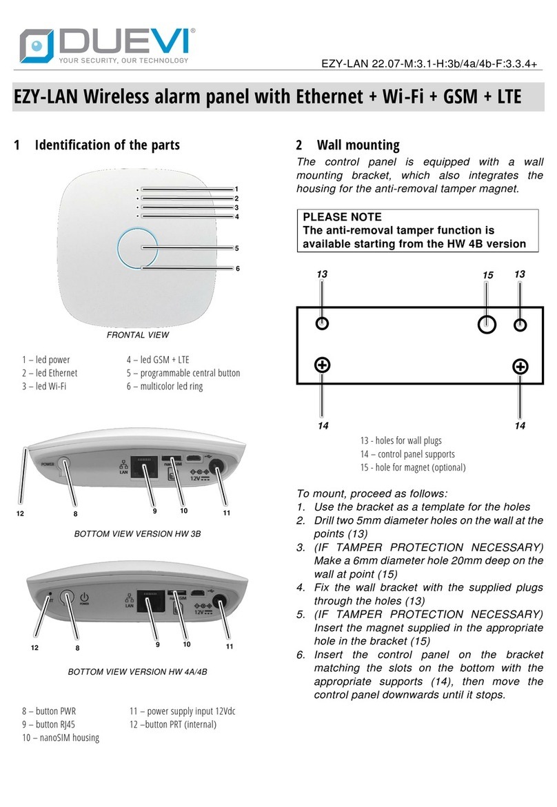
3Identification of the parts
FRONTAL VIEW
1 –led power
2 –led Ethernet
3 –led Wi-Fi
4 –led GSM + LTE
5 –programmable central button
6 –multicolor led ring
4Signals of the luminous ring
The luminous ring visible around the central
button (6), if enabled during the programming
phase, provides information on the status of the
system.
The luminous intensity of the ring (6) is reduced
after 60 seconds of inactivity of the control unit, to
reduce any disturbance at night. Return to
maximum brightness as soon as you perform an
operation on the control unit.
When the control unit is powered only by battery
(no external power supply), in order to reduce
consumption, the ring (6) only flashes
periodically.
Luminous ring signals meanings (6)
Green
Disarmed
Green / Blue
(blinking)
Disarmed with door open
Green / Red
(blinking)
Disarmed with alarm memory
Red
Totally armed
Orange
Partially armed
Exit time (flashing)
Entry time (flashing)
Violet (blinking)
Alarm in progress
White (blinking)
Panel in SETUP mode
Blue (blinking)
Panel in TEST mode
1
2
3
4
5
6

5LED signals
The LEDs visible above the central button (1) (2)
(3) (4) provide information on the power supply
and connection status of the control unit.
When the control unit is powered by battery only
(no external power supply), in order to reduce
consumption, the LEDs (2) (3) (4) no longer give
any indication.
Led
Status
Indication
1
Power
off
Panel turned off
slow flashing
No power supply +
battery ok
quick flashing
Power supply present
+ battery absent
steady on
Power supply present
+ battery ok
2
Ethernet
off
cable disconnected
quick flashing
cable connected +
internet / P2P absent
steady on
cable connected +
internet / P2P present
3
Wi-Fi
off
Module turned off
slow flashing
Wi-Fi access point
mode
quick flashing
Wi-Fi router mode +
internet / P2P absent
steady on
Wi-Fi router + internet
/ P2P mode present
4
GSM / LTE
off
Module turned off
slow flashing
SIM registered / GSM
mode
quick flashing
SIM not registered or
other problems
steady on
SIM registered / LTE
mode + internet / P2P
present
6Battery
The control unit is internally equipped with a
rechargeable lithium battery, which guarantees an
autonomy of up to 15 hours in the absence of an
external power supply.
When the battery level drops below the minimum
operating threshold, the control unit switches off
automatically, to preserve battery life. The
control unit automatically switches back on when
power is restored.
7Control of the panel
The panel can be controlled by:
•Keyfob / remote control
•APP for smart devices
This is the privileged tool, thanks to which
you have complete control of the system in
real time.
•SMS messages
8Using the keyfob /remote control
Before being used, the remote control must have
been configured in the control panel by the
installer.
Button 6 requests the system status from the
control panel and then displays:
TOTALLY ARMED Led 1/2/3/4 steady ON
DISARMED Led 1/2/3/4 flashing
PARTIALLY ARMED Led 1/2 steady ON
Led 3/4 OFF
Buttons 1-2-3-4, when pressed briefly, perform
the operation for which they were programmed in
the control panel (arming, disarming, scenario
activation, etc)
Button 5, when pressed for at least 5 seconds,
can generate a panic alarm or a silent alarm (if
programmed in the control panel)
If the keyfob does not receive a response from the
control panel (e.g. because it is out of range) or
the control panel cannot carry out the command,
LEDs 5 and 6 flash simultaneously
9Using the App
The control unit can be controlled via a dedicated
App available for IOS and Android systems on the
relevant stores.
The first time the App is run, the graphical
interfaces must be updated.
To connect to a control panel, it must be added to
the list of devices to be managed.
Enter SETTINGS -> MANAGE DEVICES and
perform one of the following actions:
•SEARCH LOCAL DEVICES - automatically
searches for control panels connected to the
same local network to which the App device
is connected. In some cases, the modem /
router or the device itself may block this type
of request, so it will be necessary to proceed
with the manual addition (next point)
•ADD WITH SERIAL / QR CODE - manually
enter the serial / scan the QR code on the
control panel label.
BUTTON + LED 1
BUTTON + LED 3
BUTTON + LED 5
BUTTON + LED 2
BUTTON + LED 4
BUTTON + LED 6

Press the "Back" button to return to the Home
Page of the App, where you will find your control
panel.
Click on the name of the control panel to reach
the login page (LOGIN).
Enter your username and password, then press
the ENTER key.
Use the following QR codes to download the App.
APP for iOS (Apple)
APP for Android
9.1 Home page
As soon as you log in, the main screen (Home)
will open, displaying information on the status of
the control panel.
Here you can change the arming of the system by
using the buttons:
•Disarm: Disarm all sectors
•Stay: selection of the sectors to be armed
•Arm: Arm all sectors
If the “Request Code from App”function
is enabled, it will be necessary to enter
the user code to confirm the operation.
The icons at the top provide additional information
on the system, by clicking on the relevant icon:
•Excluded zones: indicates the zones
currently bypassed
•Alarm memory: indicates the zones that
generated an alarm in the last arming period
•Open doors: indicates the zones that are
open (if the function is active)
The bottom bar can be customized with links to
Actions or Scenarios. To manage the favorites

bar, click on the user icon (top right) and select
"User Settings".
From any page, you can return to the Home by
pressing the (home).
9.2 Alarm control menu
From the Home page, by pressing the icon (left
double arrow) or swiping to the left, you access
the Alarm Control Menu.
The Administrator User has access to all the items
in this menu, while the Normal User has limited
access to Sectors and Images items.
•Devices: displays the detailed status of the
paired devices (control panel included) with
indications on connection, power supply, radio
transmissions, etc.
•Zones: displays the alarm status of the zones
in real time, divided into various sectors, and
it is possible to manually exclude the zones or
the Alert signals (din-don)
•Sectors: displays the status of the sectors
•Users: displays the connected users and it is
possible to enable / disable the access of the
Installer user
•Notifications: view and change the settings
for sending notifications to the various users
•Images: displays the video verification images
of the devices on which the user is enabled
and allows to manually request new images.
•Events: displays the complete and detailed
list of the 5000 panel events
9.3 Home automation control menu
From the Home page, by pressing the icon
(right double arrow) or swiping to the right, you
access the home automation control menu.
The Administrator User has access to all the items
in this menu, while the Normal User does not have
access to the Programs item.
•Programs: displays all scheduled programs
set with the possibility of enabling / disabling
•Actions: displays and allows the execution of
all the Actions programmed in the control unit
•Scenarios: displays and allows the execution
of all the Scenarios programmed in the
control unit
•Home automation control divided by:
-Light
-Roller shutters
-Irrigation
-Gate
-Relay
It displays the status in real time and allows
manual control of all the home automation
outputs inserted in the sectors to which the
user has access.

10 Using SMS Messages
The control unit can be controlled by sending
simple SMS messages.
The control unit must have an active SIM card
connected to the telephone carrier.
SMS messages can be sent using the DUEVI
ALARM PRO app, available for IOS and Android
systems in the respective stores.
Each SMS must begin with a user code,
which uniquely identifies the user and his
authorisations in the control panel.
xxxxxx.<command>
where xxxxxx = 6-digit user code
Commands will be executed by the control
panel only if the user is enabled to
execute them.
The control panel accepts SMS commands
from any telephone number and responds
with a confirmation or error text message
SMS commands have a precise syntax
which must be respected!
Do not enter spaces or other characters
other than those indicated below.
10.1 Request system status
xxxxxx.status
The control panel responds with an SMS
containing the status of the sectors associated
with the user.
10.2 Total arm
xxxxxx.arm
The control panel arms all sectors associated
with the user.
10.3 Individual sectors arm
xxxxxx.arm.Y.Y.Y.Y
Y= number of the individual sector to arm
Examples:
arm.1.3.5
arm sectors 1+3+5
arm.2
arm sector 2
The control panel arms the individual sectors
indicated only if they are associated with the
user.
10.4 Total disarm
xxxxxx.disarm
The control panel disarms all sectors associated
with the user.
10.5 Individual sectors disarm
xxxxxx.disarm.Y.Y.Y.Y
Y= number of the individual sector to disarm
Examples:
disarm.1.2.6
disarm sectors 1+2+6
disarm.4
disarm sector 4
The control panel arms the individual sectors
indicated only if they are associated with the
user.
10.6 Enabling installer access
xxxxxx.installer.on
The control panel enables installer access.
10.7 Disabling installer access
xxxxxx.installer.off
The control panel disables installer access.
10.8 SIM Data Activation
xxxxxx.apn.Y
Y= apn address for internet access
Examples:
apn.mobile.vodafone.it
enable data for
italian Vodafone SIM
The control panel sets the indicated apn address
and enables the SIM data connection.
10.9 GSM Status Request
xxxxxx.statusgsm
The control panel responds with an SMS
containing GSM status, carrier name and signal
level.
10.10 GSM module reboot
xxxxxx.rebootgsm
The control panel performs a reboot of the GSM
telephone module.
10.11 Control panel reboot
xxxxxx.reboot
The control panel performs a complete reboot.
Other manuals for EZY-LAN
2
Table of contents
Other Duevi Security System manuals