Duevi CE-LAN User manual

CE-LAN
USER MANUAL
6.2018
MT: 2.3
H: 1.0+
F: 2.8.5+
WIN: 1.0.7.0+
APP: 1.0.24+
ENG

2
SUMMARY
1MAIN CHARACTERISTICS........................................................................................................................................3
2GLOSSARY............................................................................................................................................................3
1. USE OF THE ALARM SYSTEM ...................................................................................................................................6
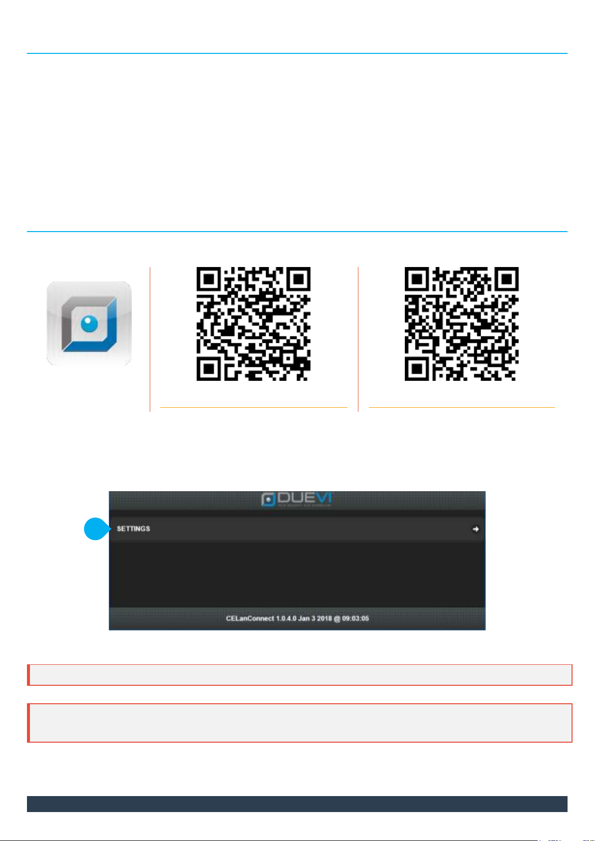
2. USING THE APP “CE-LAN CONNECT” (Windows, iOS, Android)....................................................................................6
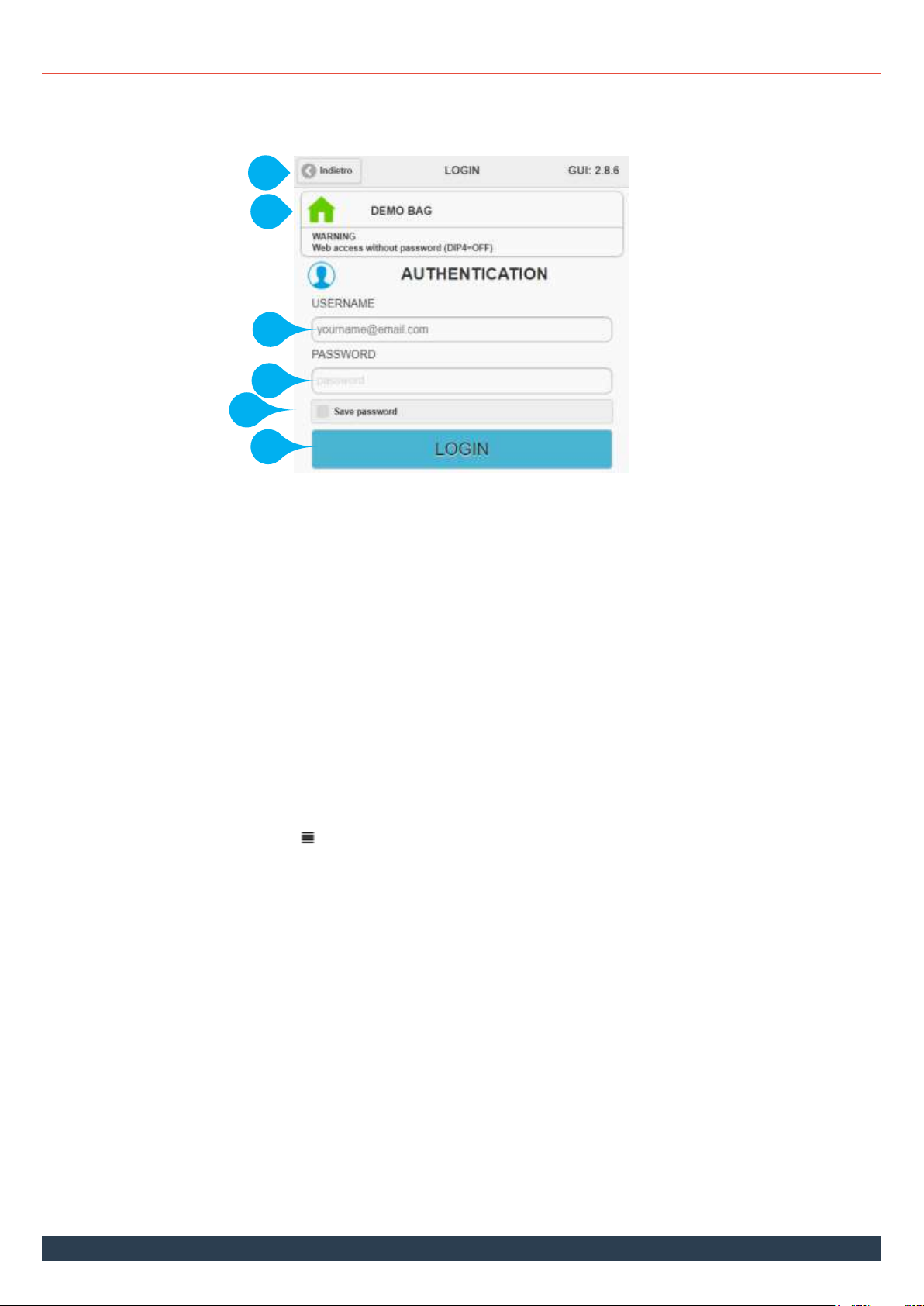
2.1 LOGIN and LOGOUT................................................................................................................................................9
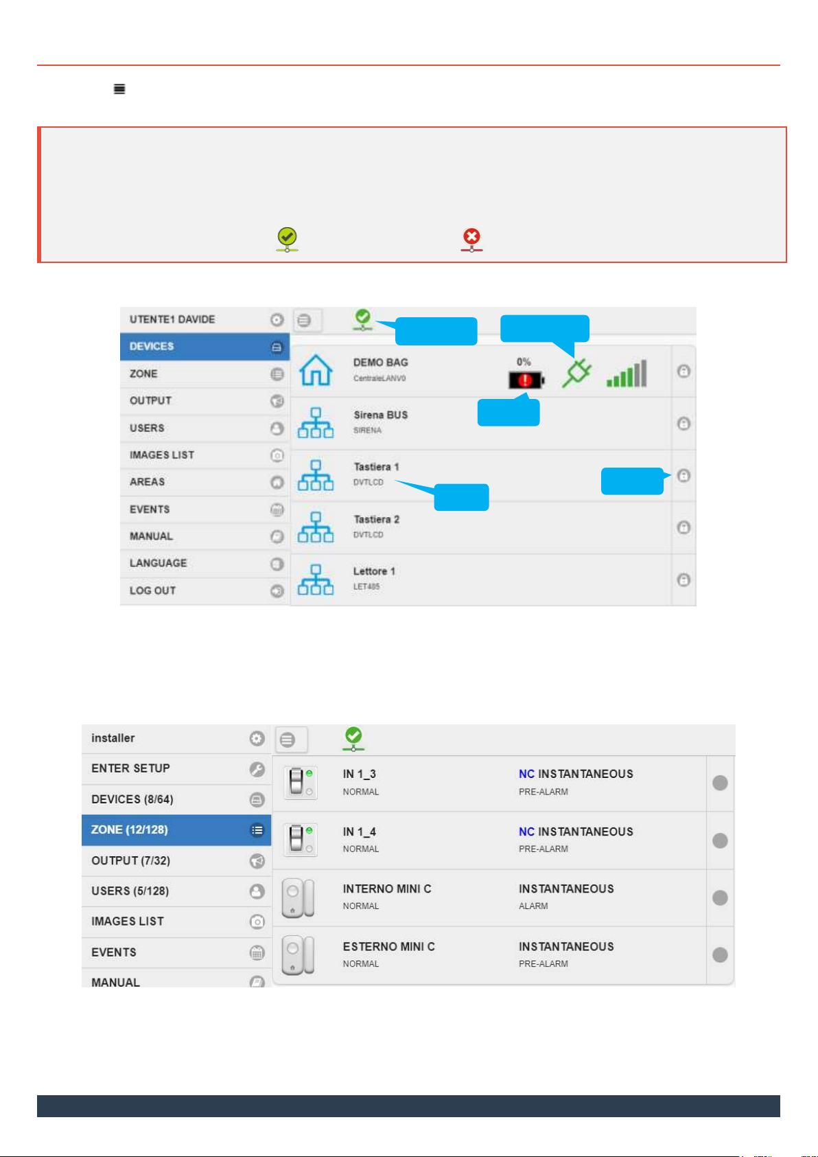
2.2 MENU ITEMS.........................................................................................................................................................10
2.3 CONTROLLO DELLE AREE ......................................................................................................................................13
2.4 ARM AND DISARM................................................................................................................................................14
2.5 MANUALLY EXCLUDING A ZONE...........................................................................................................................16
2.6 OUTPUTS...............................................................................................................................................................16
2.7 EVENTS OF THE AREA............................................................................................................................................17
2.8 SUONDS OF THE AREA ..........................................................................................................................................17
2.9 CUSTOMIZATION OF USER SETTINGS ...................................................................................................................18
3USING THE KEYPAD............................................................................................................................................. 19
3.1 DISPLAY IN STANDBY ............................................................................................................................................19
3.2 EVENT LOG AND GSM STATUS..............................................................................................................................20
3.3 SELECTION OF THE AREA TO OPERATE.................................................................................................................21
3.4 ARMING / DISARMING..........................................................................................................................................21
3.5 ALARM MEMORY..................................................................................................................................................23
3.6 SIGNALING OPEN DOORS......................................................................................................................................24
3.7 ALERT (CHIME)......................................................................................................................................................24
3.8 SOUNDS ................................................................................................................................................................24
3.9 PANIC AND SILENT ALARM ...................................................................................................................................25
3.10 SERVICE USER........................................................................................................................................................26
4USING THE TAG TRANSPONDER KEYS..................................................................................................................... 27
4.1 ARMING ................................................................................................................................................................27
4.2 DISARM.................................................................................................................................................................27
5USE OF THE KEYFOB ............................................................................................................................................ 28
5.1 FREE CONTROL OF THE AREA ...............................................................................................................................28
5.2 USE OF PROGRAMMABLE KEYS ............................................................................................................................28
5.3 TOTAL ARM AND DISARM.....................................................................................................................................29
5.4 PANIC OR SILENT ALARM......................................................................................................................................29
6USING THE SMS TEXT COMMANDS ........................................................................................................................30
6.1 REQUEST STATUS OF THE AREA............................................................................................................................30
6.2 ARMING AND PARTIALIZATION OF THE AREA......................................................................................................30
2.1. DISINSERIMENTO TOTALE DI UN’AREA.................................................................................................................31
6.3 ENABLING INSTALLER ACCESS ..............................................................................................................................31
7BLOCKING THE CALL CYCLE IN PROGRESS ...............................................................................................................31

3
1MAIN CHARACTERISTICS
CE-LAN is a new-generation Cortex dual-core microprocessor control and alarm panel.
The main features are:
CONTROL PANEL WITH AREAS
An AREA is comparable to an independent alarm system, with its own partitions (SECTORS) of the zones, adjustable
arming/disarming, versatile control and user management.
With this control panel, up to eight AREAS can be created.
Each AREA is divided into four SECTORS of zones, which can be configured as desired and can be activated independently.
The common zones between the AREAS are managed.
USERS AND ACCESS
The use of the system by users is highly simple and intuitive.
Each user can interact with the alarm system through:
oApp “CELan Connect” (for Windows, iOS, Android)
oKeypads with display
oTransponder keys
oBidirectional wireless keyfobs
oSMS text messages
It is possible to limit access to certain time slots, only to certain sectors, or to allow only temporary bypassing of some zones (patrol
or service user).
P2P INTERNET CONNECTION
The network connection (local or via internet) is the main and powerful means of communication of the control panel.
As long as the control panel is connected (to the LAN or to the 3G module) with Internet access, you can immediately access it
from anywhere! In fact, the control panel is equipped with TUNNELING technology: without any configuration of the network it is
immediately visible both locally or remotely from Internet (communication is always safe and secure).
The control panel is equipped with a switch with two ethernet ports to share the same LAN connection with other devices.
2GLOSSARY
Alert
Function that makes a "din-don" tone to Keyboards / Readers at DISARMED AREA when a Zone detects.
It is a warning that someone has entered the Area even when the system is disarmed.
Area
Main group that identifies the area to be protected.
The area is divided into sectors (max 4), which can be armed / disarmed independently.
It is possible to define up to 8 Areas per panel, each one completely independent from the others.
Powerline failure
If the 230 VAC mains power supply is absent for the programmed time, the control panel will signal.
Beep
Sound emitted by the Keypad / Reader each time you press a key or notify the user of an event
Buzzer
Acoustic signaling device inside Keypads / Readers
Tag key
Electronic key with unique digital code, which can be used to control the alarm system.
User code
A 6-digit code used to access the alarm system via Keypad or SMS
GSM/3G Module
Communication module on GSM / 3G network for remote control, push sending, calls, SMS, e-mail.
Zone Exclusion
Exclusion of some Zones so that they are not active when the system is armed.

4
Arming / Disarming
User operation to activate and deactivate the Area. When the Area is armed, the detection of a zone
generates an alarm. When the Area is disarmed, the detections of the zones do not cause an alarm.
LED
Indicator lights in different colors on the keyboards and the readers.
Reader
Device for reading TAG transponder keys.
Panic
In emergency situations it is possible to start the sound of the siren for a fixed time of 30 seconds, so as
to call attention (by pressing a keyfob button or via the keyboard). It is also started the voice call and
sending panic notifications (if enabled).
BUS Device
Device connected to the control unit by means of a communication BUS. The main devices are:
Keyboards, Readers, Sirens and Expansion Cards.
Keyfob
Electronic device via two-way radio with unique digital code, which can be used to control the alarm
system.
Sensor
Device for detecting intrusions with different technologies (magnetic contact, infrared, glass break, door
opening, etc.)
Sector
The Sector is a portion of the Area.
The Zones are assigned to the Sectors, in order to create the most suitable scenarios for the use and
protection of the Area. Each Sector can be armed / disarmed independently.
Common Sector
It is possible to share a sector among different areas.
The Zones inserted in this Sector will give alarm only if all the Areas have armed this Sector.
System sounds
The control panel warns the user with sounds (from keyboards and electronic key readers) in case of:
arming / disarming in progress
alarm events, panic, technological zones, tamper
It is possible to disable these sounds.
Keypad
Keypad with indicator lights and display with which commands are sent to the control unit.
Entry Time
It is the time available to enter the Area - passing through a Delayed Zone - and disarm before the
system considers intrusion (and therefore alarm).
If - within the Entry Time - the Area is not disarmed, the alarm starts (the sirens sound and alarm
notifications are sent). If the first zone to detect is not with Delay, the alarm immediately begins.
Violating an istantaneous zone always causes an immediate alarm.
Useful, for example, if the keypad is far from the entrance door and you must necessarily enter the
protected area to disarm the system.
Exit Time
It is possible to set a waiting time that - starting from the arming command - does not detect alarms
until the protected area is abandoned.
At the end of the Exit Time the Area is normally armed.
Useful for activating the alarm system from inside the Area and being able to exit without causing an
alarm even crossing different zones (which will become active only at the end of the Exit Time).
Outputs
There are six outputs on board the control unit, which are activated depending on the associated event
(eg: to switch on a light flasher in the event of an alarm or activation of a telephone dialer)
Installator User
The Installer user is a special user who can check the status of all the devices (such as the
Administrator) but can also intervene on the control panel programming. Its remote access can take
place ONLY following the authorization by a user Administrator. The installer can not know the arming
status of the areas.

5
Administrator User
Administrators users can:
switch the system on and off (from: app, keypad, radio remote control, transponder key)
according to their own permissions
see the status of the area and its events
receive alerts (emails, SMS messages, calls)
view the users of the control panel and enable access to the Installer
view the status of the control panel devices
view the events of the system (not only in the area)
view the complete archive of alarm images memorized by the control panel
Normal User
Normal users can:
switch the system on and off (from: app, keypad, radio remote control, transponder key)
according to their own permissions
see the status of the area and its events
receive alerts (emails, SMS messages, calls)
Zone
The Zone (of Alarm) is the basic element that gives the control unit the status of a door or wi ndow, or a
series of sensors connected to it, or other types of control of the Area.
For each zone corresponds, generally, a protected space of the house, a room or simply a sensor
24H Zone
A zone set up as 24h is active 24 hours a day, so it is not subject to activation or deactivation of the
system.
In case of detection, the zone will give an alarm with a low intensity sound. Useful function for example
using flood sensors, thermostats, smoke or gas detectors.
Example: it is possible to have a prompt indication that a gas leak is present and to pilot a possible
solenoid valve (through one of the outputs) to block the flow of gas and avoid the danger.

6
3USE OF THE ALARM SYSTEM
To interact with the system there are different ways (depending on the composition of the system):
APP “CE-LAN CONNECT”
This is the privileged tool, thanks to which you have complete control of the system in real time.
Keypad with display
Tag key
Keyfob
SMS text command
4USING THE APP “CE-LAN CONNECT” (Windows, iOS, Android)
It is possible to download the "CELan Connect" app from the Apple and Google Markets (hereinafter the QR Code links):
CELan Connect
iOS (Apple)
Android
https://itunes.apple.com/it/app/celan-connect/id1235456893?mt=8
https://play.google.com/store/apps/details?id=it.duevisrl.celanmob
"CELan Connect" is also available in Windows® version (compatible with Windows 7 SP1 and later): ask your installer for the software
installation file.
Once installed, the application provides the control interface of the control panel.
Figure 1 –Home page of the APP
EVERY FIRMWARE VERSION OF THE PANEL HAS ITS OWN GRAPHIC INTERFACE.
IT IS ADVISABLE TO VERIFY AND EVENTUALLY UPDATE THE APPLICATION REGULARLY TO HAVE THE INTERFACE
CORRESPONDING TO THE CONTROL PANEL FIRMWARE VERSION.
1

7
Pressing "SETTINGS \ MANAGE GRAPHIC INTERFACES" opens the window to manage the interfaces and create virtual panels (Figure 2):
Figure 2 –Interfaces management page
1. UPDATE GRAPHICAL INTERFACES: check online for updates and downloads new versions (requires Internet connection):
when the symbol is (grey) it means that the interface is available for that version of control panel but it has not been downloaded
(so can not be used) or has been deleted
when an update is available for an interface, the icon is added to the symbol (green)
2. INTERFACE: this line indicates the presence of the interface for a specific firmware version of the control panel:
(grey): the interface is available but has not been downloaded or has been deleted
(green): the interface is available and is updated
(green) + : the interface is available and usable but there is an update (press " UPDATE GRAPHICAL INTERFACES")
3. ENABLE checking and downloading of updates for this interface / firmware version
4. DELETE the files of the selected interface (ex. because it is no longer in use): in this way the space on the device is freed, but it will not
be possible to connect to the control panels with that firmware version (you will need to download the interface again)!
5. BACK: return to the previous screen
Initially, the list of control panels is empty (Figure 1).
On the body of the central unit or on the electronic board there are the reference data of the control panel:
MAC ADDRESS and SERIAL / DEVICE ID
QR CODE (to use with appropriate function on the app)
To add / delete a control panel, open the "SETTINGS / MANAGE DEVICES" screen:
Figure 3 –"Device Management" page of the application
1
2
5
3
1
2
3
4
4
4

8
The different ways to add a control panel are:
SEARCH LOCAL DEVICES perform a RESEARCH of the panels in the local network and add them to the list (Figure 3-1).
ADD WITH SERIAL performs a MANUAL addition of a control panel via a UNIQUE SERIAL CODE. (Figure 3-2)
(ONLY IOS AND ANDROID APP) ADD WITH QR CODE activate the device's camera to scan the QR CODE of the control panel and
adds it to the list (if valid).
To delete all the already added control panels, press the DELETE ALL THE DEVICES button (Figure 3-3).
To delete a single control panel, press the Xkey on the control panel line (Figure 3-4).
To go back to the previous screen, press the button Back (Figure 3-5)
Once added to the management menu, the control panels appear on the main application screen:
Figure 4 –List of panels managed by the app
The colour of the icon indicates:
(green) = The control panel is online and can be programmed / used
(green + orange arrow) = The control panel is online and can be programmed / used; an interface update is available (see
"SETTINGS> MANAGE GRAPHIC INTERFACES")
(green + red cross) = The control panel is online but the graphical interface was not donlowaded (see "SETTINGS> MANAGE
GRAPHIC INTERFACES")
(grey) = The control is not connected at the moment

9
4.1 LOGIN and LOGOUT
Touch the name of a control panel in the list to connect to the control panel (Figure 4):
A new window opens with the login page (login, Figure 5):
Figure 5 –Login page
1. Press the button Back to go back to the panel list
2. Name assigned to the control panel and connection status with the panel:
“GREEN HOME” = the control panel is online and the connection is established
“GREY HOME” = the control panel is not reacheable at the moment. Communication problems or panel offline.
FIRMWARE Version: indicates the firmware version of the control panel.
3. "USERNAME" field - Enter here the user name for access to the control panel.
4. "PASSWORD" field - Enter the password chosen for the user. The password must be at least 8 characters and no more than 15.
5. SAVE PASSWORD - If you enable this function, the access datas will be stored for the future connection.
6. LOGIN - After entering "user name" and "password", press the LOGIN button to access the control panel.
Once logged in, the interface shows the "Menu" button and - depending on the type of user who logged in - a different content on the main
page (see the following paragraphs).
To open / close the side panel, press the " MENU" button.
To LOGOUT (disconnect the user from the system), press the "Menu" button and then "LOGOUT".
2
3
4
5
6
1

10
4.2 MENU ITEMS
The button “ MENU” opens the user menu to check the system status.
Depending on the type of User (Normal, Administrator), some items are not displayed:
NOTE: The connection icon indicates in real time the connection status with the control panel. In the case of a non-stable remote
connection, it is possible that the software temporarily loses its connection to the control panel. This is normal and depends on the quality
of the connection. Consider that the information displayed in this condition will not be updated until the
connection is re-established.
= ONLINE = OFFLINE
“DEVICES” (Administrator and Normal User)
In this menu you can see the status of the devices (control panel, radio sensors, radio sirens, keypads, transponder key readers, expansion
cards): battery level, amount of radio signal, power supply, tamper.
“ZONE” (Only Administrator)
In this menu you can see in real time the status of the zones (at rest, in alarm ...).
It is possible to order the display for an easier reading choosing between "Full list" (list of all zones in order), "By zone type" (list divided by
type of zone, eg: infrared, vibration ....), "By device" (list divided by different devices, eg: control panel, expansion card, radio sensor…).
Tamper
Battery
Device
Mains Power
Connection

11
“OUTPUT” (Only Administrator)
In this menu it is possible to see in real time the status of the control panel outputs, to which different devices can be connected (eg: lights,
acoustic signals, telephone dialers ...). Typically, the outputs are associated with events (eg: alarm, low battery, input status ...) and are
activated accordingly.
If an output has been programmed to "manual control", it can be triggered by touching the corresponding button.
“USERS” (Only Administrator)
In this menu you can see the complete list of Users of the control panel and in real time how many and which are connected.
The Installer user is always present and can be enabled for remote access via an ON/OFF command switch.
The Administrator can also disable other Normal users through an ON/OFF command switch.
“IMAGES LIST” (Only Administrator)
In this menu it is possible to view the complete list of events with images of the cameras stored in the control panel and to check in real time
the phases of image capture by the control panel.

12
“AREAS” (Administrator and Normal User – Default view)
This is the control center of the Area (see the descriptions of the various controls in the following paragraphs).
“EVENTS”(Only Administrator)
In this menu you can see the complete list of all the PANEL events (not just those of an Area).

13
4.3 CONTROLLO DELLE AREE
Selecting the AREAS menu accesses the control of the enabled areas:
Figura 6 –Area control
2. AREA NAME –Indicates the area on which you are operating. Press the button to select another area.
Area
1
2
3
4
5
6
7
8
9
10
11

14
3. SECTOR ICON –Indicates the status of the sector:
The sector is disarmed and there are no warnings
The sector is armed, no alarm is in progress
The sector is armed, intrusion alarm in progress
The sector is armed, but temporarily deactivated by the SERVICE user
The sector is armed, but temporarily deactivated as a Common Zone with another Area
Tamper alarm in progress
Entry or Exit time
One or more zones of the sector are open. To find out which zones are open, touch the open door icon.
4. CHANGE AREA ARMING STATUS –To change the status of the area, first touch the CHANGE button, then activate the individual
sectors to be armed (ON) or disarmed (OFF) and confirm by pressing the SEND button again.
5. DISARM ALL –Press this button (after the CHANGE button) to quickly disarm all sectors of the area.
6. ARM ALL –Press this button (after the CHANGE button) to quickly arm all sectors of the area.
7. MAIN PANEL –Displays the screen for the control of sectors and area arming / disarming.
8. SECTORS –Displays the sectors and the combined zones. The status of the zones is in real time.
It’s possible to bypass (disable) one or more zones by touching the zone name (zone is active with the symbol ).
Bypassed zones do not generate an alarm when the corresponding sector is armed.
Each time the bypass is changed, the control panel sends a notification as a reminder to the user (if enabled).
9. OUTPUTS –Displays the status of the outputs in real time.
10. EVENTS –Displays events in the area in chronological order (from the most recent).
11. OTHER –Displays the settings of the Area sounds that can be changed by the user:
Sounds / Alerts: enables / disables the sound alerts in real time (eg: alert, entry ...) from keypads and key readers.
4.4 ARM AND DISARM
THE POSSIBILITY OF ARM AND DISARM DEPENDS ON THE TYPE OF USER AND THE PERMISSIONS ASSIGNED TO IT.
IT IS POSSIBLE THAT A USER HAS ONE OR MORE OF THE FOLLOWING LIMITS:
TIME: THE USER CAN ACT ONLY IN CERTAIN TIME PERIODS
SECTORS: THE USER CAN ONLY ACT ON CERTAIN SECTORS AND NOT ON OTHERS
SERVICE: THE SERVICE USER CAN ONLY DEACTIVATE TEMPORARILY ONE OR MORE SECTORS, BUT CAN NOT PERFORM ANY AREAS ARMING
OR DISARMING
AREA: THE USER CAN NOT ACT ON THE AREA (CAN NOT LOGIN VIA APP OR ACTIVATE FROM KEYBOARD AND KEY READER)
ARMING TOTALLY THE AREA
To quickly arm totally the Area (all Sectors armed):
First touch the CHANGE button. The button will show a rotation animation and will change to SEND. For each Sector an ON / OFF
switch will appear. The ARM ALL buttons and DISARM ALL buttons become active
Press the ARM ALL button .

15
During arming operation, the Exit Time and the relative icon on the involved sectors are shown (if active).
At the end of the Exit Time, all sectors of the Area are active.
CHANGE THE ARMING STATUS OF THE AREA
To change the arming status of one or more Sectors of an Area:
First touch the CHANGE button. The button will show a rotation animation and will change to SEND. For each Sector an ON / OFF
switch will appear. The ARM ALL buttons and DISARM ALL buttons become active
Activate the individual sectors to be armed (ON) or disarmed (OFF)
Confirm by pressing the SEND button
During arming operation, the Exit Time and the relative icon on the involved sectors are shown (if active).
At the end of the Exit Time, the Sectors armed are active
DISARMING TOTALLY THE AREA
To quickly disarm totally the Area (all Sectors disarmed):
First touch the CHANGE button. The button will show a rotation animation and will change to SEND. For each Sector an ON / OFF
switch will appear. The ARM ALL buttons and DISARM ALL buttons become active
Press the DISARM ALL button . The modification is immediate, the area is disarmed
OPEN DOORS
If there are open doors, the Sector shows the symbol of "Open
Door" and by touching it it is possible to read the list of the
open Zones in that Sector (and then provide for their closure).
It is possible to program the Area so that it notifies the user in
case of Open Doors or ignores the Zones (see with your
installer the preferred setting and further details on the use of
this function).
ALARMS
In the event of an alarm (in addition to the sound of the sirens), the user is notified by push, SMS, mail or voice call alerts (depending on the
settings).
During an alarm, the Sector involved (if a zone inside it has been violated) displays the icon:
To consult the alarms that have occurred, select the "Events" button in the Area or the Menu item "Events" (in this case all the events and
alarms of all the areas will be read, only for Administrator Users).

16
4.5 MANUALLY EXCLUDING A ZONE
To manually exclude a particular zone from the arming of the relative sector:
select the "Sectors" control within the Area
open the list of the Zone of the sector (or Sectors) in which the Zone to be excluded is present
touch the zone (or zones) to be excluded: the symbol “”disappears, the zone is immediately excluded (if enabled, a notification
is sent to the user). Touching the zone again, it is included again.
The zone remains excluded until it is re-included with the same procedure.
The sector with at least one excluded zone shows this icon to indicate that an exclusion exists
4.6 OUTPUTS
This Area option allows to:
See the outputs associated to the Area, with indication of their status in real time
Activate / deactivate the outputs manually (only if programmed as "manual setting")
Tap the switch icon to activate / deactivate it manually (you will see its status change)
“” = ZONE INCLUDED
“” = ZONE EXCLUDED
Output deactive
Ouput active

17
4.7 EVENTS OF THE AREA
The list of events in the area contains sorted by date and time of each event:
Area status changes (arming / disarming, with detailed indication of the changes in the Sectors)
User who changed the status of the Area or logged in to the system
Alarms (any alarm from the Area Zones) with indication of the name of the zones in alarm and possible presence of images
System problems and anomalies (eg: no connection and reset ...)
Battery status and device power supply
IN THE EVENTS LIST WITHIN THE AREA ARE DISPLAYED ONLY THE EVENTS HAPPENED FROM THE LAST ARMING, THE
PREVIOUS EVENTS ARE ELIMINATED AT EVERY NEW ARMING.
4.8 SUONDS OF THE AREA
It is possible to activate / deactivate the Alert sounds (CHIME) and the event beeps (arming / disarming, Exit time and Input ...) emitted by
keypads and key readers, directly from the "OTHER" control in the Area:
It is possible to check the activation / deactivation status of the sounds and Alert also on the keypads with the display using the buttons:
button #= beep status button = Alert Chime status

18
4.9 CUSTOMIZATION OF USER SETTINGS
By pressing the setting icon next to the user name, you can change some user settings:
"Change password": change the password to access the app (login password)
"Keypad code": changes the 6-digit code to access the keypad control with display and to send SMS
"E-mail": changes the e-mail address associated with the user
"Tags / keyfob management": enables / disables the tag keys and the keyfob associated to the user. Useful for example in case of
loss or theft of the keys.
Warning: the key or the keyfob will not be active until they are re-enabled.
To make changes to these settings effective, press the "SAVE THE CONFIGURATION" button.
1

19
5USING THE KEYPAD
Using the keypad it is possible to:
Arm / Disarm one or more Areas (with selection of Sectors)
See the status of one or more areas
See dynamic information in real time (alarms in progress, exit time ...)
See the Event Queue (since last arming)
See the status of the GSM / 3G module (if present)
Enable / disable sounds and Alert
1. Display: shows the date and time, the status information
of the Area, the event list and the GSM status
2. F1, …, F4: each key is associated with a sector of the
Area (F1 = Sector 1, …, F4 = Sector 4).
3. 0, …, 9: used to enter user codes
4. : ALERT activation / deactivation key
5. #: sound activation / deactivation button
6. : selection of the Area and scrolling of the
items in the lists
7. : key to cancel / delete / exit
8. : confirmation button, selection, event reading of the
area and modem status
5.1 DISPLAY IN STANDBY
In stand-by (area disarmed and no event to report) the keypad shows the area name and the current date and time.
Date & time
Area name

20
5.2 EVENT LOG AND GSM STATUS
When the Area is disarmed, press the “” key to read the Event log and the status of the GSM / 3G module (if present).
EVENT LOG
The Event log contains the history of events since the last arming (at the next arming the event log is deleted).
The number in brackets indicates the total number of events present.
To read the events press the “”key:
Event reading starts with the most recent event, called E01 (Event 01).
To move to the next / previous event use the arrow keys /.
To get more details of an event, press the “”key:
Press the “”key to exit / go back.
GSM/3G MODULE STATUS
The module status is shown on the display:
For more details, press the “”key:
0
0
0
Move to next /
previous event
0
0
0
Show more details
of the event
GSM/3G
Signal level
Type of connection
Name of the
network operator
Other manuals for CE-LAN
1
Table of contents
Other Duevi Security System manuals