manuals.online logo
Brands
  1. Home
  2. •
  3. Brands
  4. •
  5. Dunster House
  6. •
  7. Shelter
  8. •
  9. Dunster House H3-GS4X35HEX User manual

Dunster House H3-GS4X35HEX User manual

INSTALLATION MANUAL
FOR
Hexagonal Utopia
Garden Shelter
H3-GS4X35HEX
Unique product reference number
.........................................................................
http://www.dunsterhouse.co.uk
Dunster House Ltd.
Queries Procedure
Important Information
Please retain all documentation with regards to your purchase.
In the unlikely event that you need to contact us, please do so in writing to:
Email: cs@dunsterhouse.co.uk
Post: FAO Customer Services, Dunster House Ltd - Factory 1, Caxton Road, Bedford, MK41 0LF
Our Customer Services department is open 9:00 - 17:00, Monday to Friday. Please include your Sales Order number
starting with SO or your postcode so we can locate your order.
The nature of timber
The timber provided for this product is a soft wood which has been kiln dried and is pressure treated for protection
against rot and insect infestation.
Timber is a natural product and inherent properties can include knots, knot holes, imperfections, cracks and warping.
Due to the inherent properties of timber we make no guarantees that the timber you receive for your product will be
free from these natural properties. We will not replace any components for any of the following reasons:
•Timber that contains knots where they do not influence the structural stability of the product
•Cosmetics appearances - colour variations
•Timber that has shakes, cracks, gaps or sap which do not influence the structural strength of the product
•Timber that has been covered or buried underground
•Twisted timber that can be installed
•Queries arising from a neglectful manner during assembly or as a result of incorrect assembly
•Queries due to modifications by the owner causing the timber to deform
Any valid queries will be satisfied by the exchange or replacement of the defective parts only on a supply only basis.
Colour transfer
This product has been pressure treated with wood preservative and a brown colour additive. Consideration should be
given to the propensity of the material to stain light colour adjacent surfaces, such as paving flags, render or coated
timber surfaces. We recommend contact between the timber and these surfaces is limited, and careful consideration to
storing the product prior to assembly should be taken in order to prevent such discolouration.
Assembly Preparation
This product has been designed for self-assembly and recommend that assembly is carried out by two DIY competent
people. It is important that the assembly instructions are followed carefully and we recommend that the assembly
instructions are read through in their entirety prior to assembly to allow you to familiarise yourself first.
We recommend ensuring that the product is assembled in an appropriate location and on an appropriate base for
the product. It is imperative that the product is installed square, level and plumb.
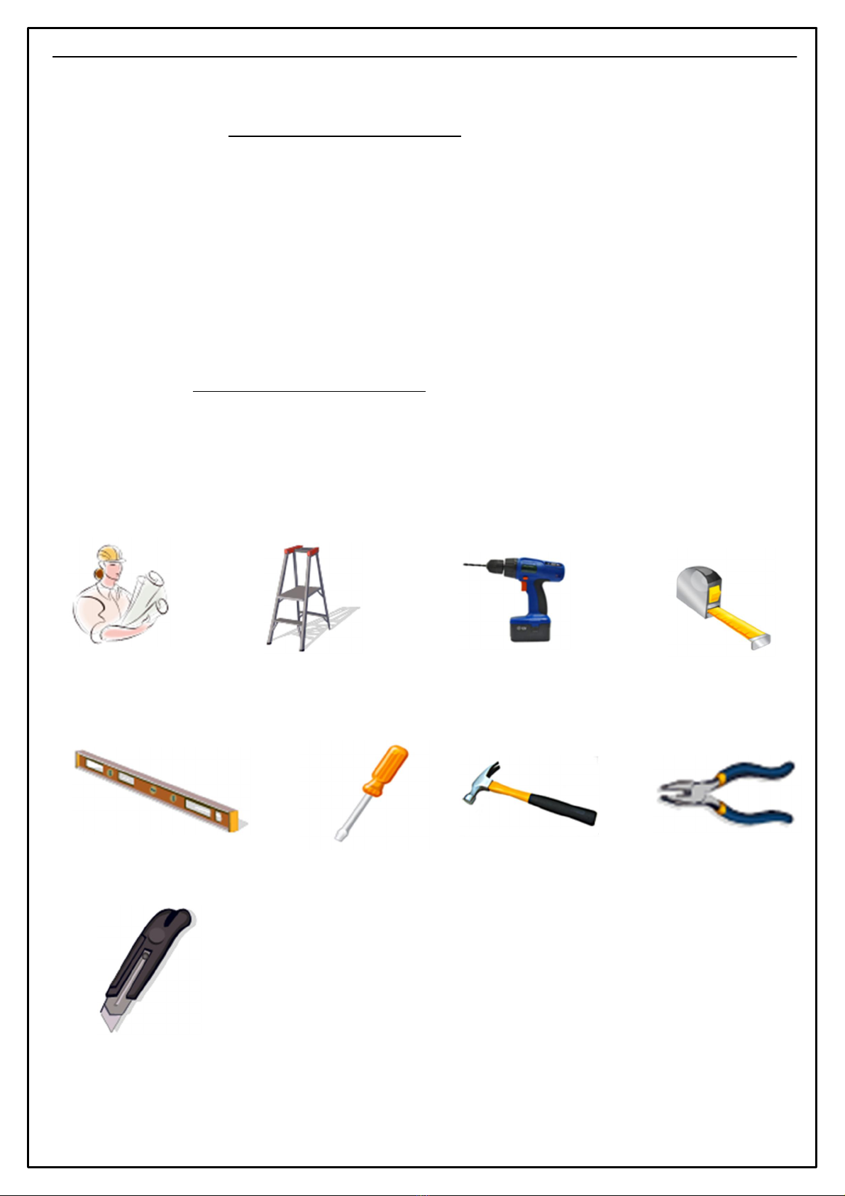
To assemble your product we recommend that you have the following:
•Stepladder
•Drill and 3mm drill bit
•Spirit level
•Tape measure
•Screwdriver
•Rubber mallet
•Gloves - if you wish for extra protection when handling pressure treated timber
All screw holes need to be pre-drilled using a 3mm drill bit (not provided) to avoid timber splitting.
Pressure treated products do not need to be treated immediately or have a timber preservative applied.
Pressure treatment does not mean that the timbers are waterproof, so you may wish to apply a water repellent.
Page 1
Hammer
Ladder Tape
measure
Spirit Level
Cordless drill/drill
Screw driver
Installation Manual for Utopia Garden Shelter
Installation
Manual
Pliers
Sharp knife
Dear customer!
The assembly of your new Hexagonal Utopia Garden Shelter requires no technical knowledge. However, it is
important that the assembly instructions are strictly followed. The assembly instruction is a combination of text and
illustrations.
Precautions:
- Assembly must only be carried out in dry and calm weather.
- Always use working gloves.
- It is essential to have an assistant.
- All holes need to be pre-drilled to avoid splitting the timber.
Tools:
The mounting of the Hexagonal Utopia Garden Shelter may require the tools shown below:
All dimensions are approximate and subject to the limitations of the material used and the methods of manufacture
Page 2
70x35x1961.A
6x Roof support
70x35x350.C
6x Post trim
70x35x650.C
12x Post trim
70x35x1948.P
6x Purlin
70x35x2360
1x Temporary support trim
86x65x1810.A
6x Wall post
Page 3
Component details for Utopia Garden Shelter
All dimensions are approximate and subject to the limitations of the material used and the methods of manufacture
350
70
35
650
70
35
2360
70
35
1961
70
35
1810
65
86
70
35
1948
70x35x2170.D
6x Roof Trim 2096
2170 70
30
HU - Roof panel bottom
6x Roof panel
HU - Roof panel top
6x Roof panel
SMB051
1x Spider Bracket
45x20x1750.A
6x Roof panel support
21x76x70(Triangle Support)
12x Triangle support
Page 4
TABLE
Description QTY
50mm Screws 145
60mm Screws 12
70mm Screws 84
90mm Screws 24
Installation instruction 1
Please note!
Before you start assembling this garden shelter, you need to prepare a correct
foundation. Only a completely leveled load bearing foundation will ensure a stable
and problem free installation, especially when aligning the door and windows.
Read the whole manual including 'post installation' page, before starting installation
of the summerhouse.
All dimensions are approximate and subject to the limitations of the material used and the methods of manufacture
Component details for Utopia Garden Shelter
45
20
1750
70
76
21.9
1183.2
2009.7
58.5
1079.1
58.5
787
Installation Manual for Utopia Garden Shelter
Page 5
Start by assembling the main frame for the Utopia Garden Shelter.
At the notched end of Wall posts (86x65x1810.A) fix Triangle support 76x70 and Roof supports (70x35x1961.A) in
the positions shown using 2x 70mm screws per end. Ensure that the notch is facing inwards in all 6 corners before fixing
and the top of the wall posts, edge of the roof support and top of the triangle support are flush.
We recommend to secure the garden shelter legs to the ground using metal brackets, metal connectors etc. (not supplied).
Position Triangle supports 76x70
approximately 428mm from the top end
of the wall post as shown, then fix the
Post braces (2x 70x35x650.C) in the
positions shown using 3x 70mm screws
and 1x 90mm screw per component.
Step 1 - Assembling shelter frame
To avoid splitting timber, please pre-drill all holes before screwing throughout the installation.
Step 2 - Fixing Post braces
All dimensions are approximate and subject to the limitations of the material used and the methods of manufacture
70mm Screw
90mm Screw
70mm Screws
70mm Screws
Flush
427.7
86x65x1810.A
70x35x1961.A
Triangle support
Triangle support
70mm Screws
Page 6
Step 3 - Assembling Purlins
All dimensions are approximate and subject to the limitations of the material used and the methods of manufacture
Using diagram above, assemble Purlins (6x 70x35x1948.P) and Spider metal bracket (SMB051) roof structure. To
fix purlins to spider metal bracket use 2x 60mm screws per purlin and screw from underneath, as shown above.
Once the roof frame has been assembled, you will need to position it on the top of the wall posts and fix it to them
using 2x 90mm screws per purlin. You will need at least 2 people to achieve this. To support the purlins and set the
roof at the correct height, position (1x 70x35x2360)- temporary post underneath spider metal bracket and
temporarily fix them into position by screwing it through middle hole in spider medal bracket with 1x 50mm screw.
60mm Screws
90mm Screws
70x35x1948.P
70x35x1948.P
70x35x1948.P
SMB051
70x35x1948.P
86x65x1810.A
SMB051
70x35x2360
50mm Screw
Step 6 - Fixing roof panels
Slide in (6x HU - Roof panel top) between purlins as much as possible so the panel sit tight
between purlins. Secure panels from underneath using 6x 50mm screws per panel, screwing
though the panel subframe. Next fix (6x HU - Roof panel bottom) in the same way as top
parts. Make sure that the panels are centrally positioned between the purlins and the overhang is
constant all around the roof assembly.
page 7
All dimensions are approximate and subject to the limitations of the material used and the methods of manufacture
Roof panel top
50mm Screws
Roof panel bottom
50mm Screws
Roof panel top
Roof panel bottom
Page 8
On the base of the main support posts, fix Post trims (1x 70x35x350.C) to each post on the outside of the shelter.
The angled end of this component needs to be pointing upwards. Use 2x 70mm screws per component to fix into
position.
Follow the instructions supplied with the shingles/roof felt (optional extra) and cover the roof panels as instructed. After
that remove temporary post from the metal bracket by unscrewing it.
Once the panels are covered, fix Roof trims (6x 70x35x2170.D) in the position shown using 4x 50mm screws per
component.
Step 6 - Fixing Roof supports and Post trims
Step 7 - Fixing Post trims, Shingles and Roof trims
All dimensions are approximate and subject to the limitations of the material used and the methods of manufacture
Position Roof panel support (45x20x1750.A) underneath the roof panel as shown below. Fix them by screwing from
the outside with 8x 50mm and 2x 70mm screws. Repeat this process for all 6 roof sections.
45x20x1750.A
View from underneath
70x35x350.C
70x35x2170.D
70mm Screws
50mm Screws
70mm Screws
page 1
Important:
•If your shingles have a peelable plastic backing remove this before installing them to the roof.
•Felt lap Adhesive is an optional extra.
Membrane:
•Place membrane over top of roof leaving a 15-20mm overhang on each side. If membrane does not overlap
whole area of roof face overlap a second piece with at least a 20mm overlap. Secure membrane to roof
boards using staple gun.
Step 1: Starting on the lowest edge of the roof, place a row of shingles over the top of the roof membrane, place slots
running upwards with the black edge of the shingle overhanging the roof by 15-20mm and nail along the bottom edge
of the tile using 4 nails provided. Carefully trim off any excess at the end of the row and keep any full 'tabs'.
Lay shingles from the center
outwards for more even placement.
20mm Clout Nails
Nails
15-20mm overhang
Membrane
Shingles
Step 2: Lay a second layer of shingles on top of the first row. This time rotate the shingles 180 degrees so that the slots
are running downwards. Nail through the center band of the tile using 4 nails supplied.
Nails
Second layer of shingles with
the slots facing downwards.
Step 3: Lay the next row of shingles with the slots in the downwards position, offsetting the tiles by half a tab. Secure by
nailing through the center band.
Apply felt lap adhesive to the underside
of each shingle tab (no amount larger
than 10mm in diameter to each corner).
'1 Tab'
page 2
Step 4: Continue to lay the shingles in a row off-set and by overlapping each row until you have reached the ridge. (Use the
off cuts to fill in the spaces at the beginning and end of the rows).
Diagram represents shingle tiles building
up across the roof boards.
Important: Adhesive layer (Bitumen) on the back of the shingles will adhese the shingles together in warm
sunlight.
Dunster House Shingles installation video - https://www.youtube.com/watch?v=IFMFYYSUEUI
page 1
Important:
•If your shingles have a peelable plastic backing remove this before installing them to the roof.
•Felt lap Adhesive is an optional extra.
Membrane:
•Place membrane over top of roof leaving a 15-20mm overhang on each side. If membrane does not overlap
whole area of roof face overlap a second piece with at least a 20mm overlap. Secure membrane to roof
boards using staple gun.
Step 1: Starting on the lowest edge of the roof, place a row of shingles over the top of the roof membrane, place slots
running upwards with the black edge of the shingle overhanging the roof by 15-20mm and nail along the bottom edge
of the tile using 4 nails provided. Carefully trim off any excess at the end of the row and keep any full 'tabs'.
20mm Clout Nails
15-20mm overhang
Membrane
Shingles
Step 2: Lay a second layer of shingles on top of the first row. This time rotate the shingles 180 degrees so that the slots
are running downwards. Nail through the center band of the tile using 4 nails supplied.
Step 3: Lay the next row of shingles with the slots in the downwards position, offsetting the tiles by half a tab. Secure by
nailing through the center band.
Apply felt lap adhesive to the underside
of each shingle tab (no amount larger
than 10mm in diameter to each corner).
Nails
Nails
'1 Tab'
page 2
Step 4: Continue to lay the shingles in a row off-set and by overlapping each row until you have reached the ridge. (Use the
off cuts to fill in the spaces at the beginning and end of the rows).
Important: Adhesive layer (Bitumen) on the back of the shingles will adhese the shingles together in warm
sunlight.
Dunster House Shingles installation video - https://www.youtube.com/watch?v=IFMFYYSUEUI
Diagram represents shingle tiles building
up across the roof boards.
page 1
20mm Clout Nails
Membrane
Felt
Plastic Waterproof Membrane:
•Place membrane over top of roof leaving a 15-20mm overhang on each side. If membrane does not overlap whole area of
roof face overlap a second piece with at least a 20mm overlap. Secure membrane to roof boards using a staple gun.
Felt:
•Starting at the lowest edge of the roof, lay the felt horizontally across the roof boards.
•Make sure that the lowest edge of the felt overhangs the eaves edge of the roof by approximately 40-50mm, and by
approximately 50mm on the front and back edges.
•Nail at approximately 200mm intervals.
•Overlap by 200mm if you need to connect two rows of felt.
•Continue laying the next layers of felt and nail into the roof boards at 200mm intervals horizontally and with 300mm
intervals vertically.
•Overlap the layers by 200mm and we recommend you seal any joints using the optional felt lap adhesive.
•Repeat this process on the opposite side of the roof.
15-20mm Overhang
Cut felt at
an angle.
Roof Mambrane
200mm Overlap
Second layer
Cut out of felt
INSTALLATION MANUAL
ADDITIONAL PANEL PACK
H3-GS4X35HEX
Unique product reference number
.........................................................................
http://www.dunsterhouse.co.uk
Dunster House Ltd.
Components Required for Utopia GS Hexagonal Gazebo
Infill Panel 2m - Solid
1860 70
850
1860 70
850
Infill Panel 2m - Glass
Page 6
All dimensions are approximate and subject to the limitations of the material used and the methods of manufacture
Utopia Garden Shelter 3m x 4m
Half Height Wall Panel Assembly
•Position the solid wall panels between Posts as shown in the diagram bellow.
•Connect Panels to posts using (6) 70mm Screws. (Repeat this process dependant on how many panels have been
purchased).
•Position a further set of panels directly above previously secured panels and connect using (2) 70mm Screws as
shown in the diagram bellow. (Repeat this process dependant on how many Panels have been purchased).
•Connect Panels to posts using (6) 70mm screws.
•2m Solid Wall Panel
•70mm Screws
Full Height Wall Panel Assembly
Window Panel Assembly
•Position Glass Wall Panels directly above previous secured Solid Wall Panels and connect using (2) 70mm Screws as
shown in the diagram bellow. (Repeat this process dependant on how many Glass Wall Panels have been purchased).
•Connect Glass Wall Panels to posts using (6) 70mm Screw.
Important: Panel diagrams shown are one
section of Hexagonal Gazebo. Please apply
instructions to all section of you installation.
70mm Screws
70mm Screws
70mm Screws

Other Dunster House Shelter manuals

Dunster House Artemis P3-3050PRG User manual

Dunster House

Dunster House Artemis P3-3050PRG User manual

Dunster House H3-GS3X6 User manual

Dunster House

Dunster House H3-GS3X6 User manual

Dunster House H4-GS3X6PRG User manual

Dunster House

Dunster House H4-GS3X6PRG User manual

Popular Shelter manuals by other brands

Shelters4Less SR1604 Assembly instruction

Shelters4Less

Shelters4Less SR1604 Assembly instruction

ABRIS MONDIAL WALKWAY SHELTER manual

ABRIS MONDIAL

ABRIS MONDIAL WALKWAY SHELTER manual

Eskimo Eskape 2600 Operator's manual

Eskimo

Eskimo Eskape 2600 Operator's manual

No Butts Bin SR1557 Assembly instructions

No Butts Bin

No Butts Bin SR1557 Assembly instructions

Kiwi Camping SAVANNA POD KC074-413 Pitching instructions

Kiwi Camping

Kiwi Camping SAVANNA POD KC074-413 Pitching instructions

TMG TMG-ST2041CV product manual

TMG

TMG TMG-ST2041CV product manual

TMG TMG-203012PST product manual

TMG

TMG TMG-203012PST product manual

Texsport 01084 instructions

Texsport

Texsport 01084 instructions

Storage Canopy C2620 Assembly manual

Storage Canopy

Storage Canopy C2620 Assembly manual

Intenda Coprivasca Installation, use and maintenance

Intenda

Intenda Coprivasca Installation, use and maintenance

Hardlife Utility C2020 instruction manual

Hardlife Utility

Hardlife Utility C2020 instruction manual

TMG TMG-ST3040V-1.0 product manual

TMG

TMG TMG-ST3040V-1.0 product manual

Gazebo penguin 77006393 instruction manual

Gazebo penguin

Gazebo penguin 77006393 instruction manual

NBB SR8304-F Assembly instructions

NBB

NBB SR8304-F Assembly instructions

Navigloo PLUS 1419 Assembly instructions

Navigloo

Navigloo PLUS 1419 Assembly instructions

KWIK GOAL 9B54 Assembly instructions

KWIK GOAL

KWIK GOAL 9B54 Assembly instructions

Shelters4Less SR1586 Assembly instructions

Shelters4Less

Shelters4Less SR1586 Assembly instructions

Sojag 500-5153231 Assembly manual

Sojag

Sojag 500-5153231 Assembly manual

manuals.online logo
manuals.online logoBrands
  • About & Mission
  • Contact us
  • Privacy Policy
  • Terms and Conditions

Copyright 2025 Manuals.Online. All Rights Reserved.