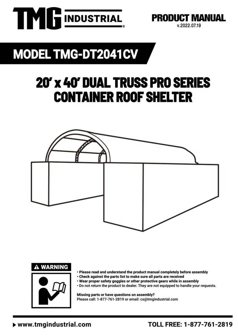
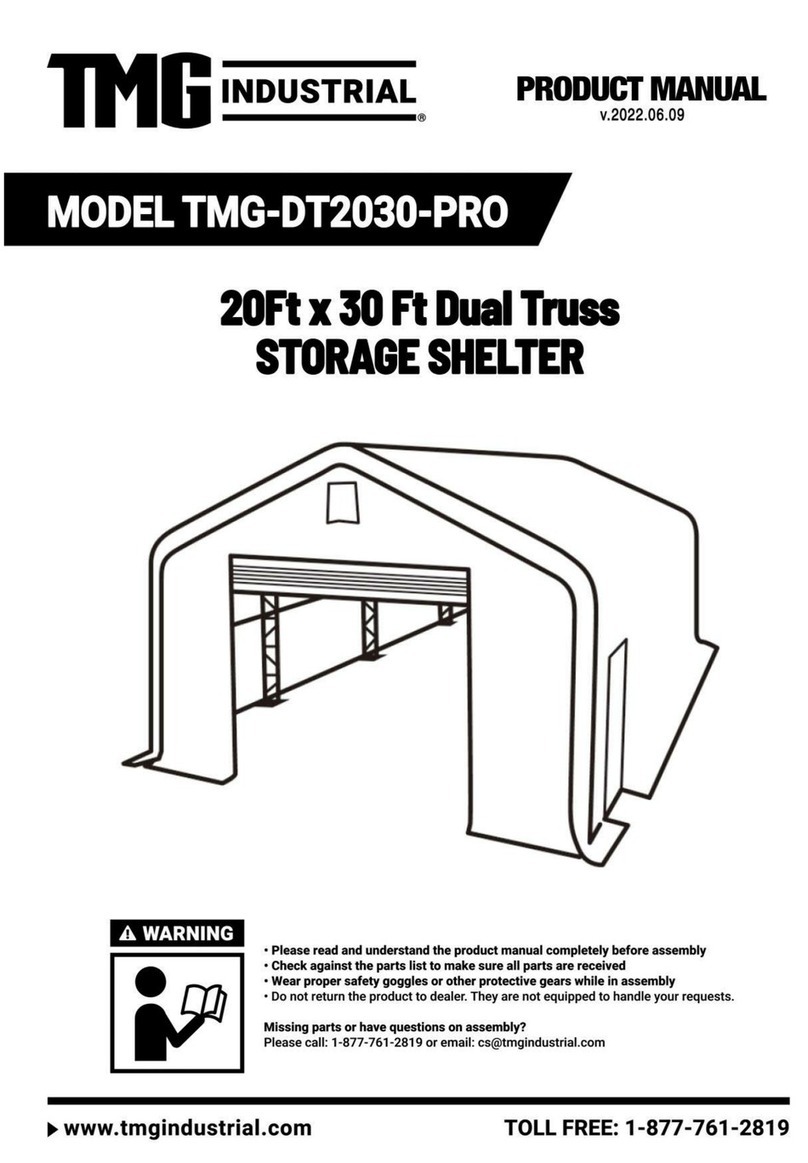
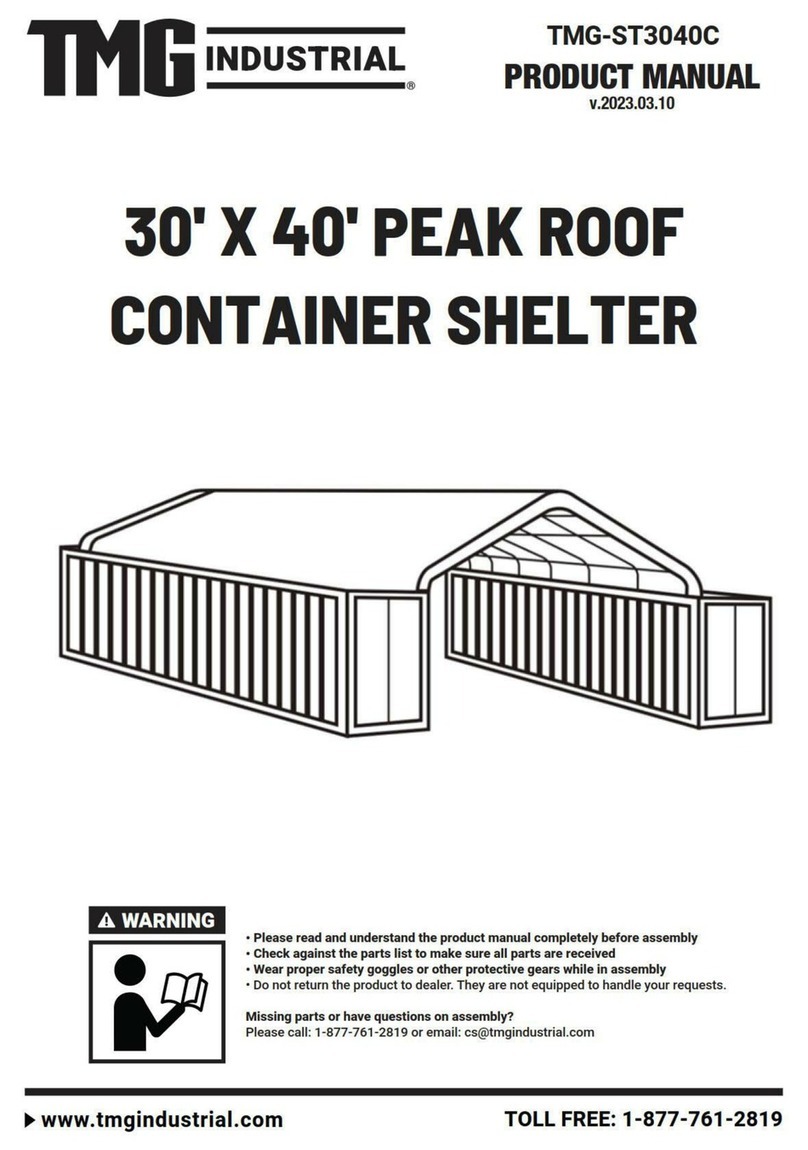
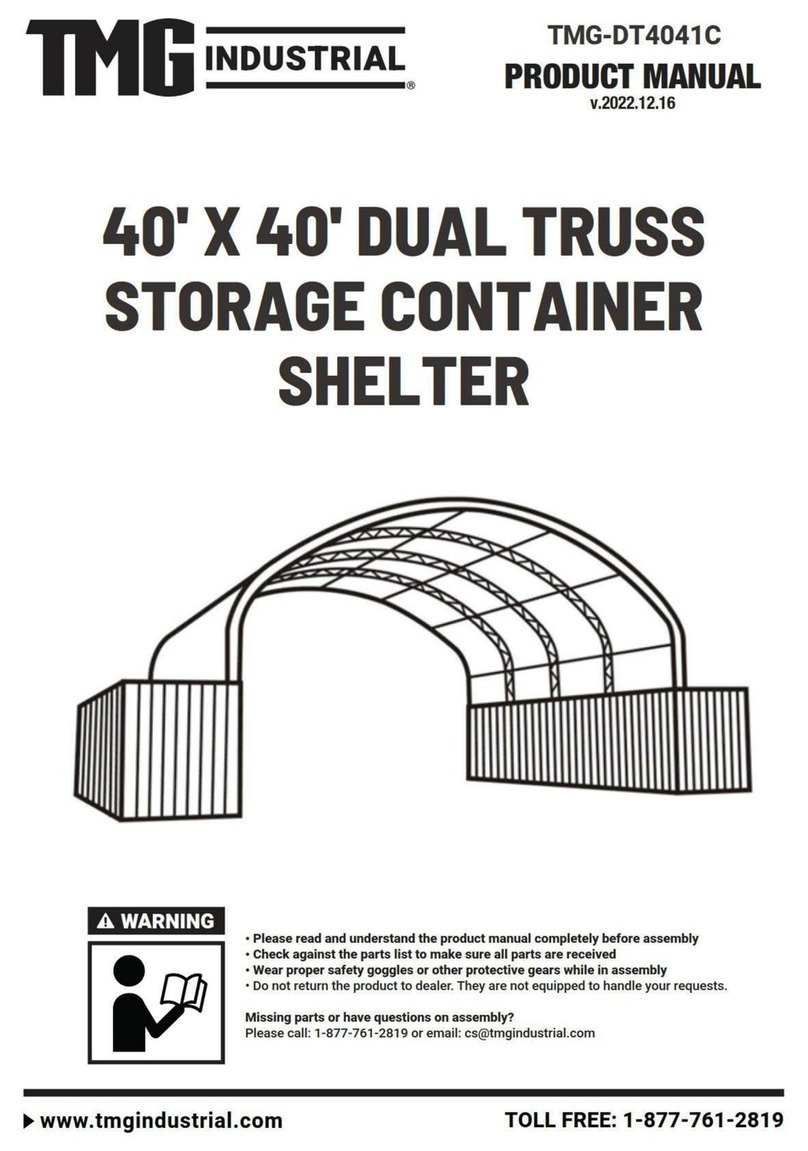
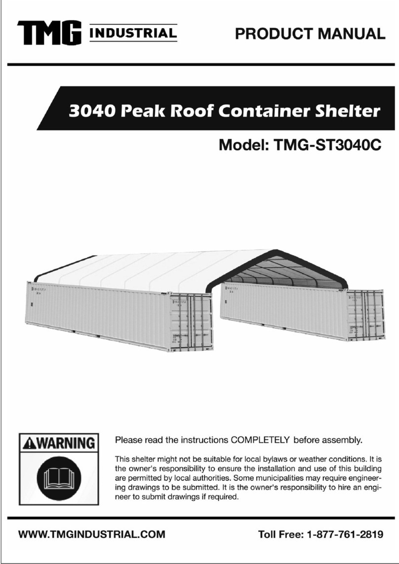
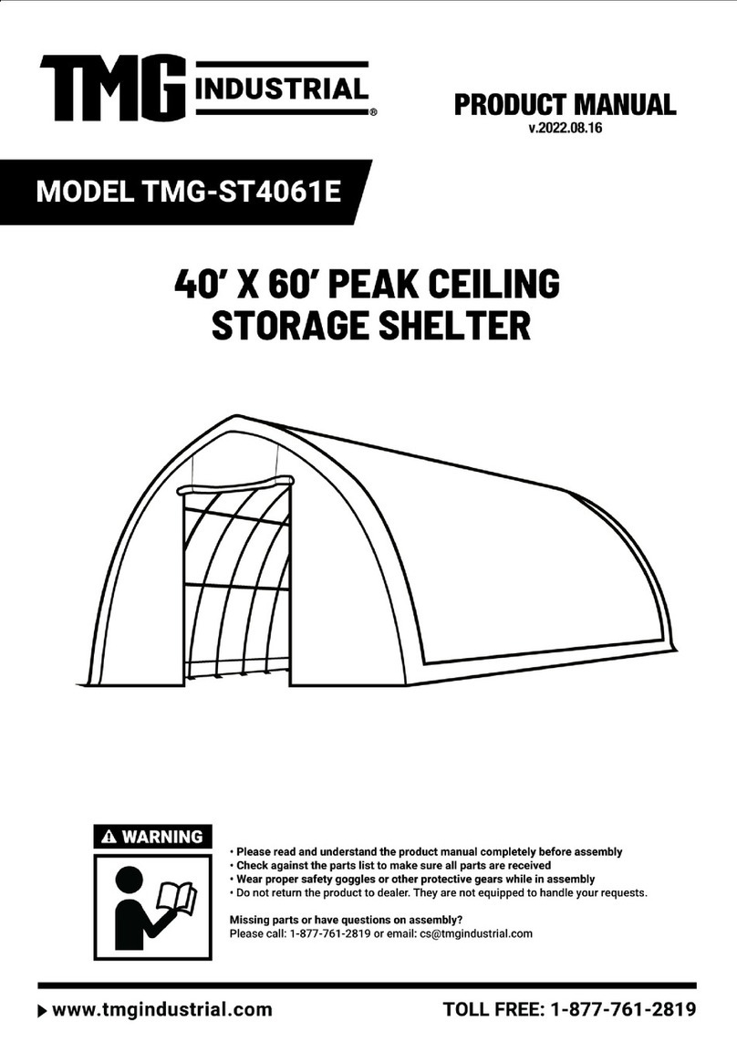
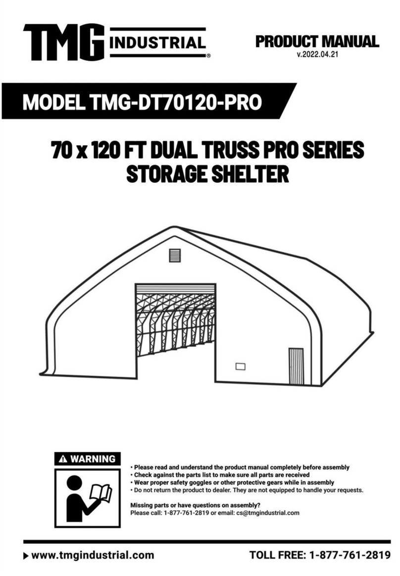
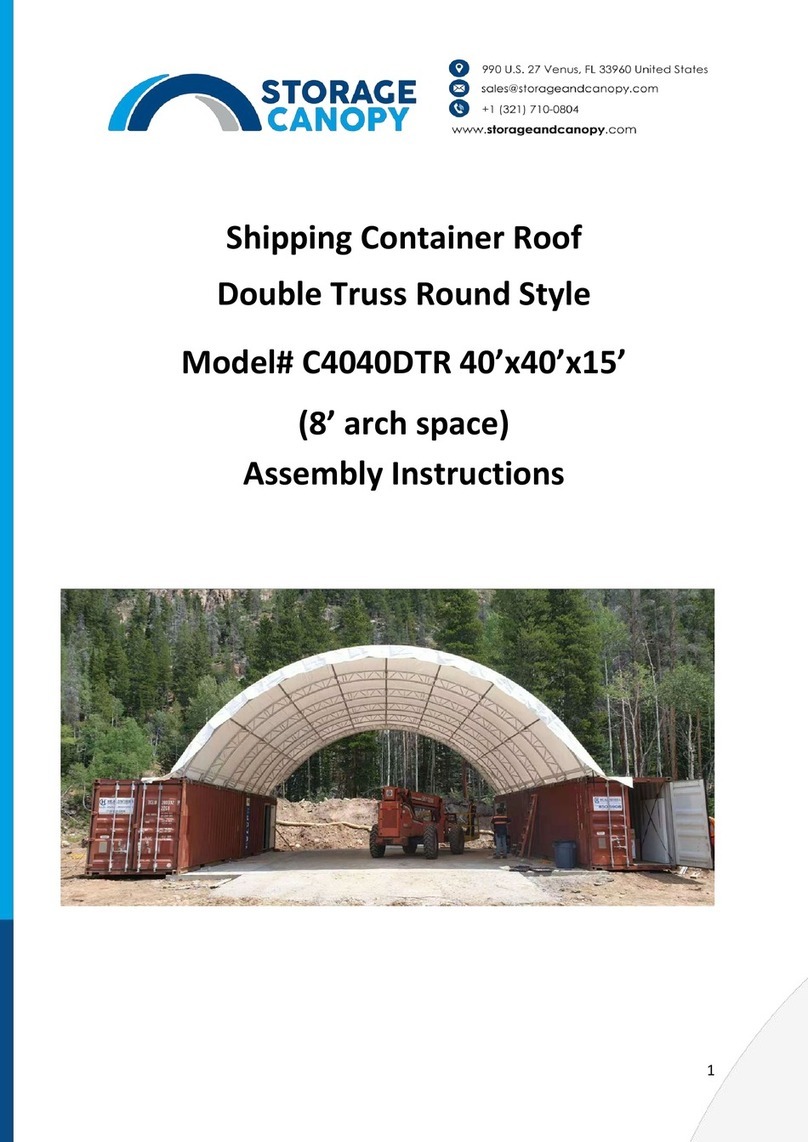
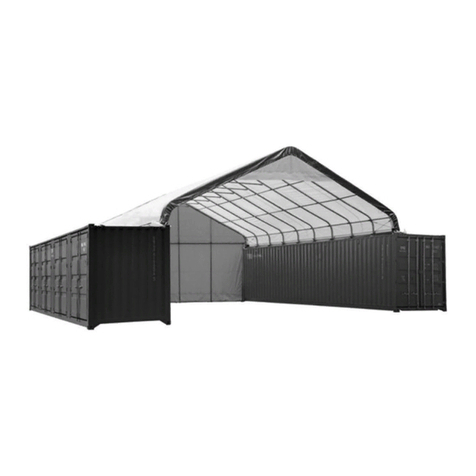
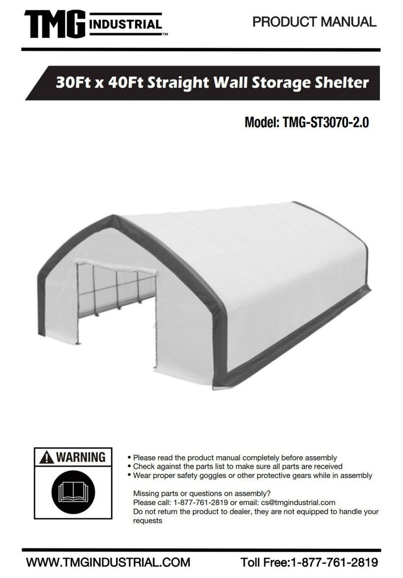
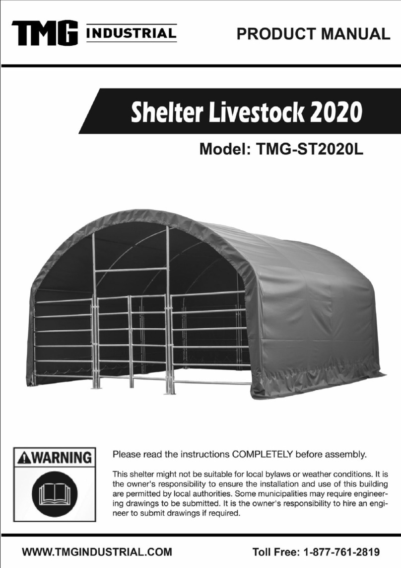
TMG TMG-ST4081V User manual

► www.tmgindustrial.com 0/19 TOLL FREE:1-877-761-2819
WARNINGS-SAFE USAGE

► www.tmgindustrial.com 1/19 TOLL FREE:1-877-761-2819
MAIN SPECIFICATIONS:
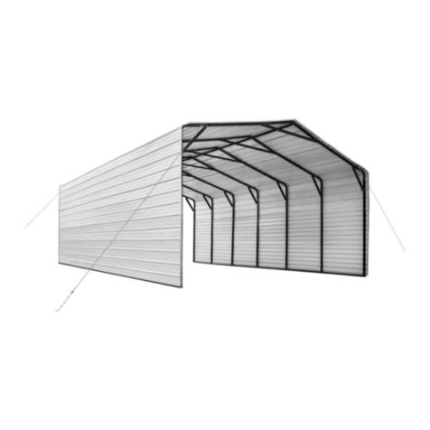
- Overall assembled size : W12 x L24 x H6.7(m) / 39.4 x 78.7 x 22(ft)
- Front and back roll up door : W4.08 x H4.87(m) / 13.4 x 16(ft)
CONCRETE FOUNDATION SIZE SEE BELOW FIGURE.
PRIOR TO ASSEMBLY
Please read the instructions carefully before installation. It is important to follow your local safety regulations and
industry standards during installation. Regulations may include but are not limited to:
-Safety helmets, protective eyewear, and clothing
-Safety harnesses for all elevated workers
- Proper ladder, cage, and safety operation
Check all components and parts before installation. All parts are marked with a part number, please refer to the parts list
to make sure you have all parts.
Choose a day with low or no wind to install, assembly is hard in heavy wind. Do not make any alterations to the structure.
Do not hang any weights on the frame during installation, including parts. We are not responsible for any damages or
injuries caused by inappropriate installation, unauthorized modifications or extreme weather.
This building is not intended for human occupancy.
It is recommended to tape or add foam/rubber on the frame where joints connect and where it touches the cover. This
will help extend the life span of the cover.

►
www.tmgindustrial.com
PARTS
CODE GRAPHICAL
1
2
2A
3
3A
4
4A
5
5A
5B
5C
6L
6R
7
7A
8
9
10
10A
www.tmgindustrial.com
2/19 TOLL FR
EE:1
TMG-ST4081V PART LIST
DESCRIPTION
Peak arch tube
Upper rafter tube
(middle truss)
Upper rafter tube
(front and rear truss)
Sidewall tube
(middle truss)
Sidewall tube
(front and rear truss)
Lower rafter tube
Lower rafter tube
Roof Purlin
(horizontal tube)
Support tube for roof frame
(middle)
Support tube for roof frame
(left and right)
Dropping tube for top roof
Left corner base plate
(front and rear truss)
Right corner base plate
(front and rear truss)
Middle truss base plate
Ratchet
Door column base plate
(front and rear truss)
Middle column base plate
(front and rear truss)
Door frame lower tube
(front and rear truss)
Door frame upper tube
(front and rear truss)
EE:1
-877-761-2819
LENGTH QTY
φ58x1935mm 21
φ58x2672mm 38
φ58x2672mm 4
φ58x3100mm 38
φ58x3100mm 4
φ58x2067mm 38
φ58x2067mm 4
φ42x1140mm 140
φ42x2250mm 19
φ42x2253mm 38
φ42x1156mm 38
6x200x350mm 2
6x200x350mm 2
6x200x200mm 38
3T 42
6x150x200mm 4
6x150x200mm 4
φ58x2783mm 8
φ58x3180mm 4

►
www.tmgindustrial.com
10B
11A
11B
12
12A
12B
13
13A
14
14A
15
15A
16
17
18
19
19A
20
21
21A
21B
www.tmgindustrial.com
3/19 TOLL FR
EE:1
Door frame centre upper tube
(front and rear truss)
Rope pulley
Rope pulley
Front and rear door crossing beam
(right)
Front and rear door crossing
beam(right)
Door center vertical supporting rod
for cross beam
Front and rear door upper crossing
tubes
(left and right)
Front and rear door upper crossing
tubes
Front and rear fabric panel tension
tubes
Front and rear fabric panel tension
tubes
Front and rear connectors
Middle truss connectors
Mounting base
Sidewall frame steel tension
cables
Self locking bolt and nuts
Half round head bolt
Hexagon bolt and nuts
Self-tapping screws
EE:1
-877-761-2819
φ58x2060mm 4
30x35x130mm 2
30x35x80mm 2
φ58x2089mm 2
φ58x2037mm 2
φ42x1143mm 4
φ42x1760mm 4
φ42x1470mm 4
φ32x1700mm, 4
φ32x1990mm 4
φ58/φ42 14
φ58/φ42 266
40x100mm 80
φ6x3200mm 40
M8x60mm 280
M8x80mm 372
M10x80mm 8
M10x30mm 130
M10x50mm 8
M8x50mm 38
#12x25mm 147

►
www.tmgindustrial.com
22
23
24
25
26
27
27A
28
29
30
31
32
33
INSTALLATION STEPS
STEP 1 :
REVIEW THE WHOLE STRUCTURE AND CHOOSE TH
Choose a solid level ground area to set up the building. Do not install in an area where the floor is soft, a wetland, cannot
take the weight, or keep the building steady.
We strongly recommend to inst all the building on a con
Do not use any anchor spikes!
Watch the surroundings! Do not set up the building near any snowdrifts. The fabric cover can hold up a certain amount of
falling leaves, light debris and win
d resistance, however, large, fast or sharp falling items and big wind might punch or
tear the fabric materials. Keep the building surroundings clear to avoid potential damages.
Be careful with power and heat sources. Do not keep heat sources near the cove
flame.
www.tmgindustrial.com
4/19 TOLL FR
EE:1
Steel tension cables
(for #7A and front and rear arches)
Water plug
Braided rope
Expansion bolt (not included)
Door dropping tube
Top cover tension tube
(for both bottom sides)
Top cover tension tube
(for bo
th bottom sides)
Top cover
Front and rear cover panel
Bungee
Nylon rope
Scratch resistant tape
Tube clamps
REVIEW THE WHOLE STRUCTURE AND CHOOSE TH
E PROPER INSTALLATION SITE
.
Choose a solid level ground area to set up the building. Do not install in an area where the floor is soft, a wetland, cannot
take the weight, or keep the building steady.
We strongly recommend to inst all the building on a con
crete foundation with all expansion bolts to secure all base plates.
Watch the surroundings! Do not set up the building near any snowdrifts. The fabric cover can hold up a certain amount of
d resistance, however, large, fast or sharp falling items and big wind might punch or
tear the fabric materials. Keep the building surroundings clear to avoid potential damages.
Be careful with power and heat sources. Do not keep heat sources near the cove
r. Do not expose the building to open
EE:1
-877-761-2819
W30xL800mm 42
φ30mm 20
φ8x300m 1
bundle
φ16x150mm 142
φ32x1993mm
φ32x2200mm
2
groups
φ32x1993mm 24
φ32x700mm 2
1
2
4
φ8x19m 4
10m 5
(φ58) 4
.
Choose a solid level ground area to set up the building. Do not install in an area where the floor is soft, a wetland, cannot
crete foundation with all expansion bolts to secure all base plates.
Watch the surroundings! Do not set up the building near any snowdrifts. The fabric cover can hold up a certain amount of
d resistance, however, large, fast or sharp falling items and big wind might punch or
r. Do not expose the building to open

►
www.tmgindustrial.com
•
Review the whole frame structure diagram as shown in Figure
have about 3 ft clearance around the building
•
Draw a r
ectangular square base line showing all positions of base plates and front and rear doors.
•
Base plates: all base
plates must be bolted firmly with expansion bolts
•
Base plate
installation is as below and all base
•
Installation diagram of expansion bolt
NO. PART
6L
6R
7
www.tmgindustrial.com
5/19 TOLL FR
EE:1
Review the whole frame structure diagram as shown in Figure
1
, decide the roll up door position, and make sure you will
have about 3 ft clearance around the building
,Diagonal line X must be equal to Y.
ectangular square base line showing all positions of base plates and front and rear doors.
plates must be bolted firmly with expansion bolts
#25
. It is concrete expansion bolt M1
installation is as below and all base
pla
tes are required to install and tie firmed on this step
Installation diagram of expansion bolt
.
QTY NO. PART
2 8
2 9
38 25
EE:1
-877-761-2819
, decide the roll up door position, and make sure you will
ectangular square base line showing all positions of base plates and front and rear doors.
. It is concrete expansion bolt M1
6.
tes are required to install and tie firmed on this step
.
QTY
4
4
142

►
www.tmgindustrial.com
STEP 2 : ASSEMBLE ALL TRUSSES.
•
The building includes 21 trusses
: (1)
front and rear trusses are installed with the
•
Both front and rear truss include the following parts. Connect all tubes with bolt (#19).
NO. PART
1
2A
3A
4A
www.tmgindustrial.com
6/19 TOLL FR
EE:1
: (1)
Front truss (1st truss), (1) rear truss (21rd truss)
, and (1
front and rear trusses are installed with the
fabric panel (#29).
Both front and rear truss include the following parts. Connect all tubes with bolt (#19).
QTY
NO.
PART
1x2
11A
2x2
11B
2x2
19
2x2
21
EE:1
-877-761-2819
, and (1
9) middle trusses. The
PART
QTY
1x2
1x2
12x2
2x2

►
www.tmgindustrial.com
•
The (19) middle trusses
include the following parts. Connect all tubes with
NO. PART
1
2
3
4
5A
www.tmgindustrial.com
7/19 TOLL FR
EE:1
include the following parts. Connect all tubes with
bolt (#19).
QTY
NO.
PART
1x19
5B
2x19
19
2x19
20
2x19
21A
1x19
EE:1
-877-761-2819
PART
QTY
2x19
12x19
2x19
2x19

► www.tmgindustrial.com 8/19 TOLL FREE:1-877-761-2819
•
Lay down all (21) trusses on the ground as figure 4 when the assembly is all completed and before moving to next
step.
NO. PART QTY
32
5

►
www.tmgindustrial.com
STEP 3 : PUT UP THE FRONT (1ST
) TRUSS.
•
Use of a crane or forklift is recommended, otherwise a team can use ropes to lift the trusses, but you have to make
sure it is safe, and
have enough manpower.
When the truss is up, tie the ropes to the heavy objects to make sure the truss will stay upright and use
connect the truss to the base
plate on both sides.
NO.
19
www.tmgindustrial.com
9/19 TOLL FR
EE:1
) TRUSS.
Use of a crane or forklift is recommended, otherwise a team can use ropes to lift the trusses, but you have to make
have enough manpower.
We
recommend 3 to 5 people to pull the truss up from different direction
When the truss is up, tie the ropes to the heavy objects to make sure the truss will stay upright and use
plate on both sides.
PART
QTY
4x
21
EE:1
-877-761-2819
Use of a crane or forklift is recommended, otherwise a team can use ropes to lift the trusses, but you have to make
recommend 3 to 5 people to pull the truss up from different direction
s.
When the truss is up, tie the ropes to the heavy objects to make sure the truss will stay upright and use
bolt (#19) to
QTY
21

►
www.tmgindustrial.com
STEP 4 : PUT UP THE REST TRUSSES.
•
Refer to
Step 3 to put up the rest trusses, connect all
span before going to next truss
, include the following parts .
NO. PART
5
5C
15
15A
www.tmgindustrial.com
10/19 TOLL FR
EE:1
Step 3 to put up the rest trusses, connect all
7 purlins (#5) with bolt (#18)
and secure all bolts firmly on each
, include the following parts .
QTY
NO.
PART
7x20
18
2x19
20
7x2
21B
14x19
EE:1
-877-761-2819
and secure all bolts firmly on each
PART
QTY
7x40
4x19
7x21

►
www.tmgindustrial.com
STEP 5 : TENSION CABLE INSTALLATION.
•
Tension cable installation : All cables are diagonally installed on each side of the interval, total
NO.
16
17
www.tmgindustrial.com
11/19 TOLL FR
EE:1
STEP 5 : TENSION CABLE INSTALLATION.
Tension cable installation : All cables are diagonally installed on each side of the interval, total
PART
QTY
4
0x2
20
x2
EE:1
-877-761-2819
Tension cable installation : All cables are diagonally installed on each side of the interval, total
40 cables.
QTY
0x2
x2

►
www.tmgindustrial.com
STEP 6 : INSTALL TH
E REMAINING PARTS ON THE FRONT AND REAR TRUSS.
NO. PART
10
10A
10B
12
12A
12B
13
13A
www.tmgindustrial.com
12/19 TOLL FR
EE:1
E REMAINING PARTS ON THE FRONT AND REAR TRUSS.
QTY
NO.
PART
4x2 14
2x2 14A
2x2 19
1x2 19A
1x2 20
2x2 21
2x2 33
2x2
EE:1
-877-761-2819
PART
QTY
2x2
2x2
18x2
4x2
8x2
2x2
2x2

►
www.tmgindustrial.com
STEP 7 : IN
STALL FRONT AND REAR COVER PANEL.
•
The door cover must be zipped. Use
rope (#
to the truss tube and spread toward both sides through each grommet along the tube. Refer to Figure 9
how to attach the rope and tie to the tube.
•
Insert the dropping tube (#14)
into the bottom groove pocket on the door cover. Tie two
both sides of the peak arch tube. Pull both ropes under through the bottom of the door
up from front and through both
pulley 11A
NO.
24
26
29
31
www.tmgindustrial.com
13/19 TOLL FR
EE:1
STALL FRONT AND REAR COVER PANEL.
rope (#
24) to lift up the front cover (#29)
from the center grommet and tie it
to the truss tube and spread toward both sides through each grommet along the tube. Refer to Figure 9
how to attach the rope and tie to the tube.
into the bottom groove pocket on the door cover. Tie two
ropes (#
both sides of the peak arch tube. Pull both ropes under through the bottom of the door
cover from the back, then go
pulley 11A
and 11B.
PART
QTY
1x
1
1x
2
1
x2
2x
2
EE:1
-877-761-2819
from the center grommet and tie it
firm
to the truss tube and spread toward both sides through each grommet along the tube. Refer to Figure 9
and 10 on
ropes (#
31) separately on
cover from the back, then go
QTY
1
2
x2
2

► www.tmgindustrial.com 14/19 TOLL FREE:1-877-761-2819
•
The rope coming out from pulley 11B must go through the upper wheel of pully 11A, then pull both ropes together
slowly and start to lift the door cover.
•
Tie both ropes to the corner base plate. Now the door cover is up. When you drop down the door cover, do not let go
too quick, otherwise it might get stuck and damage the fabric.

►
www.tmgindustrial.com
STEP 8 : INSTALL THE TOP COVER.
Do not install the cover during windy weather!
•
Unpack the top cover and place it along one of the long sides of the structure.
•
Use 3 to 5 ropes to top cover (#28)
pull the cover over the top of the structure, 2 or 3 people standing inside
ladders to push upwards will help to move the cover smooth without any damage.
NO.
28
www.tmgindustrial.com
15/19 TOLL FR
EE:1
Do not install the cover during windy weather!
Unpack the top cover and place it along one of the long sides of the structure.
pull the cover over the top of the structure, 2 or 3 people standing inside
ladders to push upwards will help to move the cover smooth without any damage.
PART
QTY
1
EE:1
-877-761-2819
pull the cover over the top of the structure, 2 or 3 people standing inside
on
QTY

►
www.tmgindustrial.com
STEP 9 : STRETCH AND TIGHTEN TOP COVER.
•
The roof cover must be stretched and tied to the front and rear truss by rope
cover. Start from the top center and go toward both side on each end. Add or cut the rope as needed.
•
P
ull and stretch the cover enough only to take wrinkles out. Repeat for the rear truss. Do not over stretch as it co
rip off the grommets.
NO.
24
www.tmgindustrial.com
16/19 TOLL FR
EE:1
STEP 9 : STRETCH AND TIGHTEN TOP COVER.
The roof cover must be stretched and tied to the front and rear truss by rope
going through the flap grommets on the
cover. Start from the top center and go toward both side on each end. Add or cut the rope as needed.
ull and stretch the cover enough only to take wrinkles out. Repeat for the rear truss. Do not over stretch as it co
PART
QTY
1
EE:1
-877-761-2819
going through the flap grommets on the
cover. Start from the top center and go toward both side on each end. Add or cut the rope as needed.
ull and stretch the cover enough only to take wrinkles out. Repeat for the rear truss. Do not over stretch as it co
uld
QTY

►
www.tmgindustrial.com
STEP 10 : TENSION THE COVER ON THE STRUCTURE FROM BOTH SIDES.
•
Insert tension tubes (#27)
slowly into the bottom groove pocket on
first tensio
n tube to avoid tearing the fabric and add one to the end of last tube
•
Repeat the same step for the other side.
NO.
23
27
27A
www.tmgindustrial.com
17/19 TOLL FR
EE:1
STEP 10 : TENSION THE COVER ON THE STRUCTURE FROM BOTH SIDES.
slowly into the bottom groove pocket on
both long sides. Add the
n tube to avoid tearing the fabric and add one to the end of last tube
(#27A)
as well.
Repeat the same step for the other side.
PART
QTY
2x2
12
x2
1x2
EE:1
-877-761-2819
both long sides. Add the
water plug (#23) on the
as well.
QTY
2x2
x2
1x2

►
www.tmgindustrial.com
STEP 11 : INSTALL RATCHET STRAPS.
•
Stretch and adjust the cover f
rom left and right, back and forth, to make sure
pocket where it aligns with
ratchet (#7A)
it.
•
Evenly adjust all ratchets on both sides
NO.
7A
22
www.tmgindustrial.com
18/19 TOLL FR
EE:1
STEP 11 : INSTALL RATCHET STRAPS.
rom left and right, back and forth, to make sure
it is square and centered. Cut the groove
ratchet (#7A)
, and use strap (#22) to pull tension tube (#27)
toward the ratchet and secure
Evenly adjust all ratchets on both sides
to take wrinkles out and make the cover flat and smooth.
PART
QTY
21
x2
21
x2
EE:1
-877-761-2819
it is square and centered. Cut the groove
toward the ratchet and secure
to take wrinkles out and make the cover flat and smooth.
QTY
x2
x2

► www.tmgindustrial.com 19/19 TOLL FREE:1-877-761-2819
AFTER THE INSTALLATION
Walk around and inspect the shelter periodically to make sure all components are still firmly secured and the whole
shelter is well supported. Check all bolts and nuts as well as all connection points to make sure they are all in good
position. Check the base plates, adjust the ropes and tie downs if required and clean the cover regularly.
Snow accumulating on the fabric cover must be removed as soon as possible. If snow becomes solid ice on the cover, it
will increase the weight on the roof and may collapse the shelter or reduce the life span.
Keep the shelter on a dry ground most of the time. Do not keep the fabric dirt skirt under water all the time, otherwise
the fabric will deteriorate.
We strongly recommend you remove any snow from the roof immediately. Do not leave any snow load on the roof
overnight. Keep 3 feet of clearance on all sides at all times. Do not allow snow to accumulate and pile up on the sides of
the building. Otherwise the pressure from the sides will push inwards and could lead to a collapse.
Table of contents
Other TMG Shelter manuals
Popular Shelter manuals by other brands

No Butts Bin
No Butts Bin SR1558 Assembly instructions

Gazebo penguin
Gazebo penguin 7171001 instruction manual

Shelldome
Shelldome SH-RO204015 instructions

Dometic
Dometic Kampa AIR Shelter 200 Installation and operating manual

Game Day Gear
Game Day Gear SKY 110130 quick start guide

NBB
NBB SR8306 Assembly instructions

No Butts Bin
No Butts Bin SR1586-F Assembly instructions

No Butts Bin
No Butts Bin NSKCS01ZC Assembly instructions

Shelters4Less
Shelters4Less SR1551 Assembly instructions

AGF
AGF COLLECTanDRAIN 5680A installation instructions

Clam Corp
Clam Corp CLAM 2000 quick start guide

Glasdon
Glasdon MODUS 770 FLAT PACK ASSEMBLY & FIXING INSTRUCTION LEAFLET