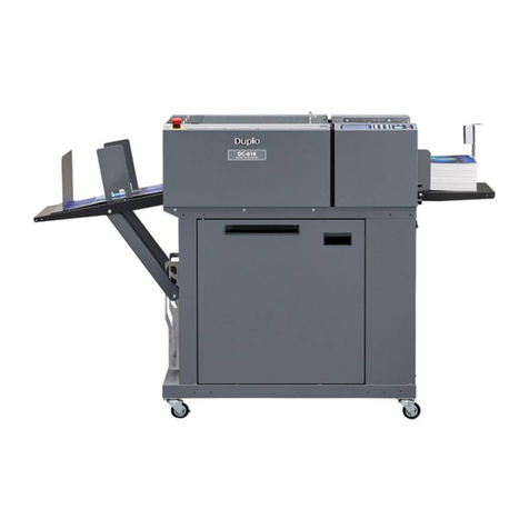
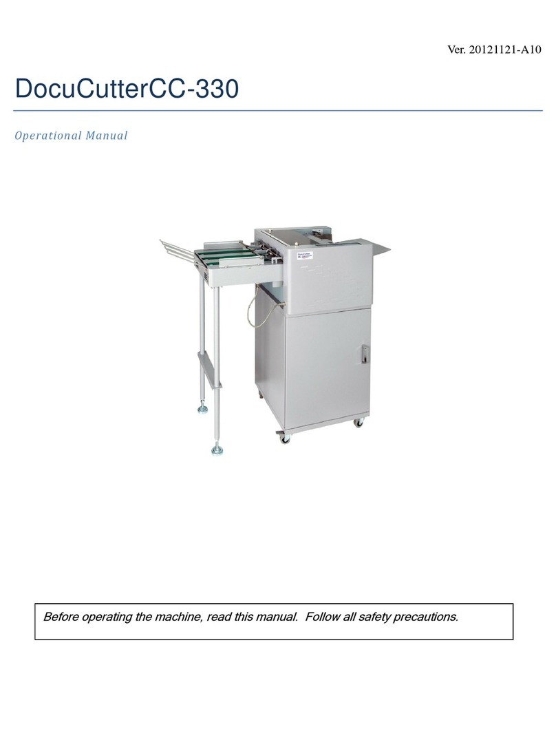
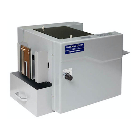
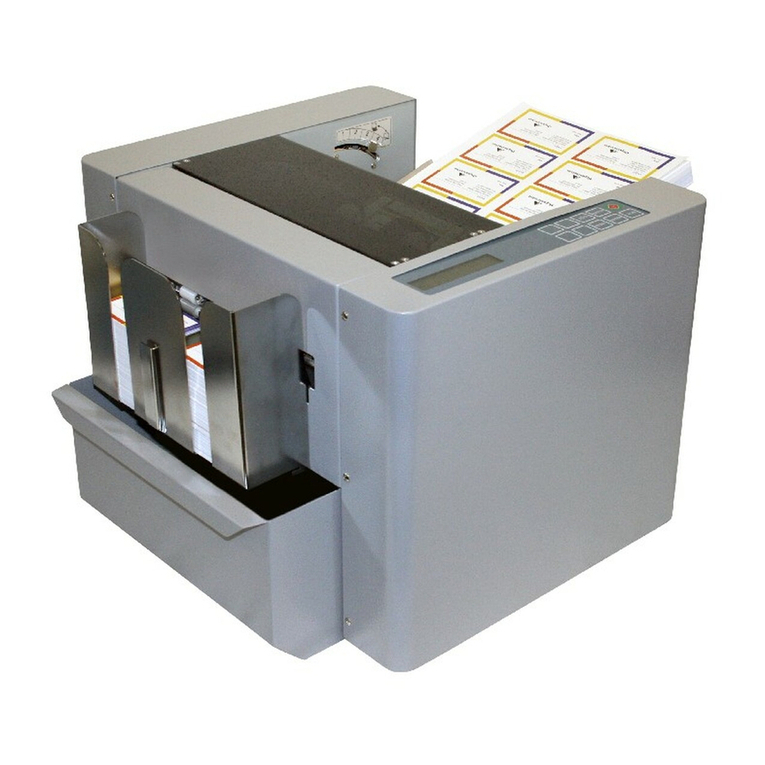
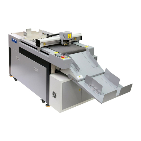
Duplo DC-618 User manual

INSTRUCTION MANUAL
CPM-08
DC-618 Cross Tool Module


i
Introduction
Thank you for your purchase of the DC-618 Cross Tool Module.
To ensure safe and efficient long-term use of this product, read and thoroughly understand this
manual before using the product. After using this manual, be sure to keep it in a handy place for
reference.
Pictorial Symbols and Other Notations used in this manual
: Introduces instructions for correct operation of the product.
If these instructions are ignored, the product may not operate at optimum
performance or may break down.
: Introduces information that is useful for operation and maintenance of the
product, or information about the product’s performance, etc.
IMPORTANT
REFERENCE
(→P.00 xxxx): Indicates the page number and item containing related information.
PLEASE NOTE
In the interest of upgrading our products, specifications and other data given in this
manual are subject to change without notice. If the manual contains anything that you do
not understand, contact the dealer for clarification.
Trademarks
●Microsoft and Windows are either registered trademarks or trademarks of Microsoft
Corporation in the United State and/or other countries.
●All other trademarks are the property of their respective owners.

ii
Notes on Safety (Please Read and Observe)
A circle with a line through it indicates a prohibited action.
The particular act prohibited is indicated by a picture inside the circle.
(In the example shown here, the prohibited act is disassembly.)
A black disc indicates an instruction, or sometimes a prohibited action.
The instruction itself is indicated by pictorial symbols drawn in white on
the disc. (In the example shown here, the instruction is Remove the plug
from the outlet.)
Various symbols and pictures are used in this manual and on the labels affixed to the machine.
These symbols and pictures provide warnings and instructions to prevent danger to you or other
personnel, and to prevent damage to office property.
The meanings of these symbols and pictures are explained below.
Indicates a high degree of potential danger. Failure to heed the warning
may lead to death or serious injury.
Indicates a medium degree of potential danger. Failure to heed the
caution may lead to injury or damage to property.
<Examples of Pictorial Symbols>
WARNING
●Precautions for Use
Safety Precautions
WARNING
CAUTION
●If the machine is used after foreign matter (metal fragments, water, or liquid) has
entered the machine, this may result in fire or electric shock.
→Turn the main unit’s power switch OFF, and then remove the power plug from
the outlet. Contact the sales distributor.
●If the machine is used after heat, smoke, a strange smell, or other abnormality
has been detected, this may result in fire or electric shock.
→Turn the power switch OFF, and then remove the power plug from the outlet.
Contact the sales distributor.
●Do not insert or drop metal, flammable material, or any other materials through
the ventilation holes into the interior of the machine.
→Doing so may result in fire or electric shock.
●Keep the machine away from a pin, wire, or other metallic or foreign objects.
Do not allow liquid to enter the machine through its openings or gaps.
→Malfunctions and a fire or electric shock may result.
●Do not place flower vases, flowerpots, cups, or water containers (including metal
containers) on top of the machine.
→Fire or electric shock may result if liquid spills inside the machine.

iii
CAUTION
●Caution for Cleaning
●Before cleaning the machine, turn offthe power switch and unplug the power
cord.
→If the machine is activated accidentally, it may cause injury.
●Do not use flammable sprays or solvents inside or near the machine.
→Gas may accumulate inside the machine causing a fire or explosion.
●Preventing Injury to Hands or Fingers
●The Cross Tool Module contains uncovered upper tools. Keep your hands or
fingers offinside it.
●Use pliers or a similar tool to remove jammed document.
Be sure to unplug the power cord before removing jammed document in order to
prevent an electric shock.
WARNING

iv
Chapter 4
Chapter 3
Chapter 2
Chapter 1
Contents
Introduction................................................................................. i
Notes on Safety (Please Read and Observe)....................................... ii
Before Using This Module
Parts Names and Their Functions .................................................... 2
Appearance .......................................................................... 2
Inside of the DC-618 ............................................................... 4
How to Remove and Install the CPM (Cross Tool Module) ....................... 5
Removing the CPM (Cross Tool Module)....................................... 5
Installing the CPM (Cross Tool Module) ........................................ 6
How to Replace a Rotary Tool ......................................................... 7
Removing a Rotary Tool from the Rotary Tool Unit ........................... 7
Attaching a Rotary Tool to the Rotary Tool Unit ............................... 9
Adjusting the Depth of a Rotary Tool ...........................................10
Programming a JOB on the Control Panel
Before Programming a JOB...........................................................12
Standby Screen ....................................................................12
JOB Entry.................................................................................14
Setting for the CPM (Cross Tool Module) .....................................15
Wizard ...............................................................................16
Direct - Advanced Mode ..........................................................20
Direct - Simple Mode..............................................................24
Error Messages ....................................................................29
Basic Operations
Processing Documents by Retrieving a Saved JOB..............................32
Process ...................................................................................34
Adjust......................................................................................36
Environment..............................................................................37
Programming a JOB on a Computer
PC Controller Setting ...................................................................40
Main Screen ........................................................................40
Wizard ...............................................................................43
Direct.................................................................................62
Retrieving and Processing a Saved JOB ...........................................72
Setting Default Values for a JOB .....................................................73
Environment ........................................................................73
Function Setting .........................................................................75
Process ..............................................................................75
Adjust ................................................................................76

v
Chapter 5
Chapter 6
Chapter 7
Troubleshooting
If a Message Appears ..................................................................80
If a Document Jam Has Occurred....................................................81
J05 CHECK MARGIN/SLOT2 ...................................................81
Daily Maintenance
Daily Maintenance ......................................................................86
Specifications
Specifications ............................................................................88

MEMO

1
Chapter 1
1
Before Using This Module
This chapter contains essential information that you should know such as the part
names of the machine and how to remove and install the module.
Parts Names and Their Functions ......................................................... 2
Appearance ............................................................................... 2
Inside of the DC-618 .................................................................... 4
How to Remove and Install the CPM (Cross Tool Module) ............................ 5
Removing the CPM (Cross Tool Module)............................................ 5
Installing the CPM (Cross Tool Module) ............................................. 6
How to Replace a Rotary Tool .............................................................. 7
Removing a Rotary Tool from the Rotary Tool Unit ................................ 7
Attaching a Rotary Tool to the Rotary Tool Unit .................................... 9
Adjusting the Depth of a Rotary Tool ................................................10

2
Parts Names and Their Functions
Appearance
No. Name Function
1 Fixing screw Loosen this when removing the CPM (Cross Tool Module)
from the DC-618.
Secure this when having installed the CPM (Cross Tool
Module) in the DC-618.
2 Adjustment knob Adjusts the depth of the rotary tool.
Turning this clockwise makes the depth deeper and turning this
counterclockwise makes the depth shallower.
Adjust the depth of the rotary tool depending on the types of it
attached to the rotary too unit. (→P.10)
To replace the rotary tool, turn this counterclockwise until
it stops to raise the rotary tool to the upper limit position.
(→P.7)
3 Color label Install the CPM (Cross Tool Module) in a slot of the DC-618,
to which the color label affixed is the same as this on the CPM
(Cross Tool Module).
You can install the CPM (Cross Toll Module) in slot 2 only.
4 Guide assy Supports the conveyance of a document.
Remove this when replacing the tool.
(→P.7)
5 Hand knob When removing the rotary tool from the rotary tool unit,
remove this.
When attaching the rotary tool to the rotary tool unit, secure
it with this.
(→P.9)
1
1
4
23
5

2
3
Parts Names and Their Functions
1
Before Using This Module
RTU (Rotary Tool Unit)
Adjustment knob
Hand knob
Rotary tool
Lower tool

4
Parts Names and Their Functions
• When having removed a module, reattach it correctly as shown in the figure above.
• Especially when reinstalling the center slitter module in slot 2 or 3, make sure that it is
installed in the correct position and in the correct orientation.
IMPORTANT
Inside of the DC-618
No. Name Function
1 Belt suction unit The suction fan sucks up documents one by one and the
feed belt feeds each of them.
2Double feed detection
section Detects a double feed with the ultrasonic sensor.
3 CCD section Reads a REG mark and a barcode.
4 Slot 1 Install the margin slitter module here.
5 Slot 2 Install the center slitter module1, the CPM (Cross Tool
Module), or the RTM (Rotary Tool Module)(option) here.
6 Slot 3 Install the center slitter module2 or the RTM (Rotary Tool
Module)(option) here.
7 Gutter deflector section The gutter deflectors automatically move according to gutter
positions and drop gutter slits in the waste box.
8 Creaser section Creases a document perpendicularly to the document feed
direction.
9 Cutter section Cuts a document perpendicularly to the document feed
direction.
2 134568 79

5
1
Before Using This Module
Disconnect the connector of the CPM (Cross Tool
Module).
Loosen the two fixing screws on the CPM (Cross
Tool Module).
Grasp the handles to take out the CPM (Cross Tool
Module) by lifting it upward.
How to Remove and Install the CPM (Cross Tool Module)
Removing the CPM (Cross Tool Module)
Open the top cover.
Top cover
Connector
Fixing screw
Handles
CPM
CPM
Fixing screw

6
How to Remove and Install the CPM (Cross Tool Module)
Connect the connector of the CPM (Cross Tool
Module).
You can install the CPM (Cross Toll Module) in slot 2 only.
Grasp the handles and install the CPM (Cross Tool
Module) in slot 2.
REFERENCE
Close the top cover.
Installing the CPM (Cross Tool Module)
Top cover
Make sure that the pins on the both sides are
securely fitted in the module and secure the two
fixing screws.
CPM
Fixing screw
Handles CPM
Put the handles down horizontally as shown in the
figure on the right. Otherwise, the top cover is not
closed completely.
Fixing screw
Connector

7
1
Before Using This Module
Removing a Rotary Tool from the Rotary Tool Unit
The CPM (Cross Tool Module) processes documents with the following two types of rotary tools
attached to the rotary tool unit. Select a proper rotary tool and attach it to the rotary tool unit.
Remove the guide assy.
Turn the adjustment knob counterclockwise until it
stops.
The rotary tool rises up to the upper limit.
Guide assy
Adjustment knob
Perforation tool:
A tool having cutting blades and
grooves that are alternatively
arranged. Enables you to perforate
a document.
Micro perforation tool:
A tool having narrower cutting
blades and grooves than the
standards type (perforation tool) that
are alternatively arranged. Enables
you to perforate a document.
Guide assy
1. Release the lock of the catch. 2. Remove the guide assy from the hook.
Guide assy
REFERENCE
1. Pull the lower part of the guide assy toward you
with the hook as the fulcrum to release the lock
on the catch.
2. Tilt the guide assy and pull it upward to remove
it from the hook.
How to Replace a Rotary Tool
Hook
Hook
Catch

8
How to Replace a Rotary Tool
Remove the rotary tool.
Rotary tool
IMPORTANT
●Do not hold the cutting edge when reattaching
the rotary tool.
●Be careful not to bring the rotary tool into
contact with the lower tool to avoid damaging
it.
Turn the hand knob counterclockwise to remove it.
REFERENCE
Do not lose the hand knob.Hand knob

2
9
How to Replace a Rotary Tool
1
Before Using This Module
Attaching a Rotary Tool to the Rotary Tool Unit
Turn the hand knob clockwise to secure the rotary
tool.
Attach the guide assy.
Attach the rotary tool in the direction of the arrow.
REFERENCE
1. Fit the guide assy onto the hook.
2. Push the guide assy in the direction of the arrow
until it is securely fitted into the catch.
Rotary tool
Hand knob
Guide assy
Hook
Guide assy
1. Fit the guide assy onto the hook. 2. Securely fit the guide assy into the
catch.
Guide assy
IMPORTANT
●Do not hold the cutting edge when reattaching the
rotary tool.
●Be careful not to bring the rotary tool into contact
with the lower tool to avoid damaging it.
Turn the adjustment knob counterclockwise until it
stops.
The rotary tool rises up to the upper limit position.
Adjustment knob
Catch

10
How to Replace a Rotary Tool
Adjusting the Depth of a Rotary Tool
Refer to the followings to adjust the depth of the two types of the rotary tools (the perforation tool
and the micro perforation tool).
Turn the adjustment knob counterclockwise until
it stops, where the rotary tool is raised to the
uppermost position (0 degrees in the figures in step 2).
Referring to the figures below, adjust the depth of the
perforation tool and of the micro perforation tool
by turning the adjustment knob clockwise.
Adjustment knob
315 degrees 0 degrees
Perforation tool Micro perforation tool
0 degrees
225 degrees 225 degrees
REFERENCE
●Adjust the adjustment knob referring to the point at which the▼is pointing.
If the depth of the rotary tool is set out of the range specified above, it may damage
the rotary tool.
●The position of the adjustment knob may vary depending on the diameter of a rotary
tool even if the same type of tool is used.
●When processing light weight documents, if a rotary tool is at a deeper position, it
may not be able to perform a document processing straight to a finished product.
In that case, adjust the depth of the rotary tool slightly shallower (toward the upper
limit position).

Chapter 2
2
Programming a JOB on the Control Panel
This chapter describes how to program a JOB on the control panel of the
DC-618.
Before Programming a JOB...............................................................12
Standby Screen ........................................................................12
JOB Entry.....................................................................................14
Setting for the CPM (Cross Tool Module) .........................................15
Wizard ...................................................................................16
Direct - Advanced Mode ..............................................................20
Direct - Simple Mode..................................................................24
Error Messages ........................................................................29

12
Before Programming a JOB
Standby Screen
This section describes the functions which are related to the CPM (Cross Tool Module).
For other settings, refer to Chapter 2 Programming a JOB - Before Programming a JOB in the
DC-618 Instruction Manual.
●Touching the details icon displays the details of
the JOB selected.
When a JOB that uses the CPM (Cross Tool
Module) is selected, touching displays CPM.
12
Other manuals for DC-618
1
This manual suits for next models
1
Table of contents
Other Duplo Cutter manuals

Duplo
Duplo DocuCutter DPC-400 User manual

Duplo
Duplo DocuCutter CC-229 Quick start guide

Duplo
Duplo DC-646 User manual

Duplo
Duplo DC-618 User manual

Duplo
Duplo DocuCutter CC-228 Building instructions

Duplo
Duplo DC-646 User manual

Duplo
Duplo DocuCutter CC-330 Building instructions

Duplo
Duplo DC-535 User manual

Duplo
Duplo DocuCutter CC-330 Quick start guide

Duplo
Duplo DocuCutter CC-229 Building instructions