Dyson DC24 Blueprint Limited Edition User manual

Service manual
Issued Jan 08


Service manual
Product overview Technical info. Fitting notes Parts recognition
General notes
Motor and yoke assembly replacement - removal
Motor and yoke assembly replacement - fitting
Stabiliser and pedal replacement - removal
Stabiliser and pedal replacement - fitting
Valve wheel replacement
Valve hose replacement - removal
Valve hose replacement - fitting
Valve hatch replacement - removal
Valve hatch replacement - fitting
Switch and powercord - removal
Switch and powercord - fitting
Duct assembly replacement - dismantle
Duct assembly replacement - fitting
Sub assemblies - wand handle assembly
Sub assemblies - cyclone assembly
Sub assemblies - bin assembly
Sub assemblies - cleaner head assembly
Electrical safety testing
Electrical circuit
Electrical fault diagnosis
Main body
Motor assembly
Cyclone and bin assemblies
Cleaner head assembly
Wand and hose assemblies
Contents
This manual is written specifically for Dyson trained engineers and covers the full DC24
range. The service instructions assume the engineer has the approved tools and test
equipment with them.
Features 01
69
70
71
72
73
05
05
18
26
30
33
34
35
37
39
41
45
51
56
60
61
63
65
02
03
04
Page

Technical info.
Service manual
Ultra-lightweight and compact
DC24 is our lightest upright machine.
What’s more, the handle compresses
so you can store it in small spaces.
Reversible wand
For cleaning awkward areas.
Washable lifetime HEPA filter
HEPA filter is ideal for allergy sufferers.
Dyson BallTM technology
Steers smoothly with a turn of the wrist.
No extra costs
Washable filters and no bags to buy.
Hygienic and quick to empty
Just press the button at the top of the cyclone
and the dust empties from the bottom.
Fingertip brush control
Tu rn brushbar on and off at the touch of a button.
Clear binTM
Made of tough polycarbonate,
lets you see when it needs emptying.
On-board accessory tool
Nozzle converts to a brush tool for dusting.
Dyson CycloneTM technology
Patented technology that doesn’t lose
suction power as you vacuum.
BALL
Concentrated technology
All round performance. But only 2/3
the size.
Independent brushbar motor
Deep cleans carpets. To othed belt
doesn’t slip or need replacing.
Product overview
01

Technical info.
Service manual
02
Electrical safety testing
Ensure that at all times during the repair and testing of products
that customers, pets, children and you are not exposed to any
Live electrical supply.
Insulation test
The following tests must be performed
prior to and upon completion of all
repairs to Dyson floorcareproducts and
beforeany functionalchecks. You must
ensurethat a full visual inspection
of the product is completed prior to
repair.
Test results
An insulation test reading of >2 MΩ
is acceptable.
A reading of below 2 MΩis not considered
safe and further investigation, rectification
and testing must be completed before the
product is used. The following components
must be visually inspected:
The wiring behind the upright switch•
cover.
All wiring behind the switch housing.•
If you cannot repair a product with an
insulation test reading of below 2MΩ
you must inform the customer that the
product is unsafe to use.
Please inform the customer of the
required actions to repair the product
(including the charge structure).
If the product is left un-repaired please
indicate on your paperwork/hand held
device that the product is electrically
unsafe and attach a ‘WARNING:
product electrically unsafe’ sticker in
a visable location on the product.
The Seaward Primetest 200 (or equivalent)
should be used to test the electrical
insulation of a Class 11 appliance; it
indicates any electrical leakage.
Test the two screws highlighted in the
upright switch cover.
Test thetwo screwshighlighted in the
rear of the duct assembly.
Insulation test points:
These tests are vital toavoid any
possibility of personal injury to the
end user.

Technical info.
Service manual
03
Wiring Schematic
Live
Neutral
BB Motor
Vac Motor
Switch area
Upright
Switch
Brushbar
Switch Main On/Off
Switch
PCB Assembly
Vac motor
area
Cleaner Head Assembly
TCO Reset
Button
(normally closed)
J3
J2
J1
Jockey Wheel-
Japanese models only
(normally open)
COMPONENT
Vac motor 8.5 Approx
Cleaner head assembly
Brushbar motor
TERRITORY RESISTANCE (Ω)
All other components
TEST POINTS
10 to 11 UK/Euro (230/240V)
16 to 17
UK/Euro (230/240V)
UK/Euro (230/240V)
23 to 24
Vac motor 2.4 Approx
Cleaner head assembly
Brushbar motor
US/Can (120V)
Vac motor 2.25 Approx
Cleaner head assembly
Brushbar motor
Japan (100V)
10 to 11
16 to 17
23 to 24
10 to 11
16 to 17
23 to 24 Japan (100V)
Japan (100V)
All 1 Max
725 Approx
400 Approx
420 Approx
120 Approx
135 Approx
85 Approx
US/Can (120V)
US/Can (120V)
Wire colours may vary between territories
1234
5
6
11
10
12
13
15
14 16
18
23
20
24
22
21
17
19
9
78

Technical info.
Service manual
04
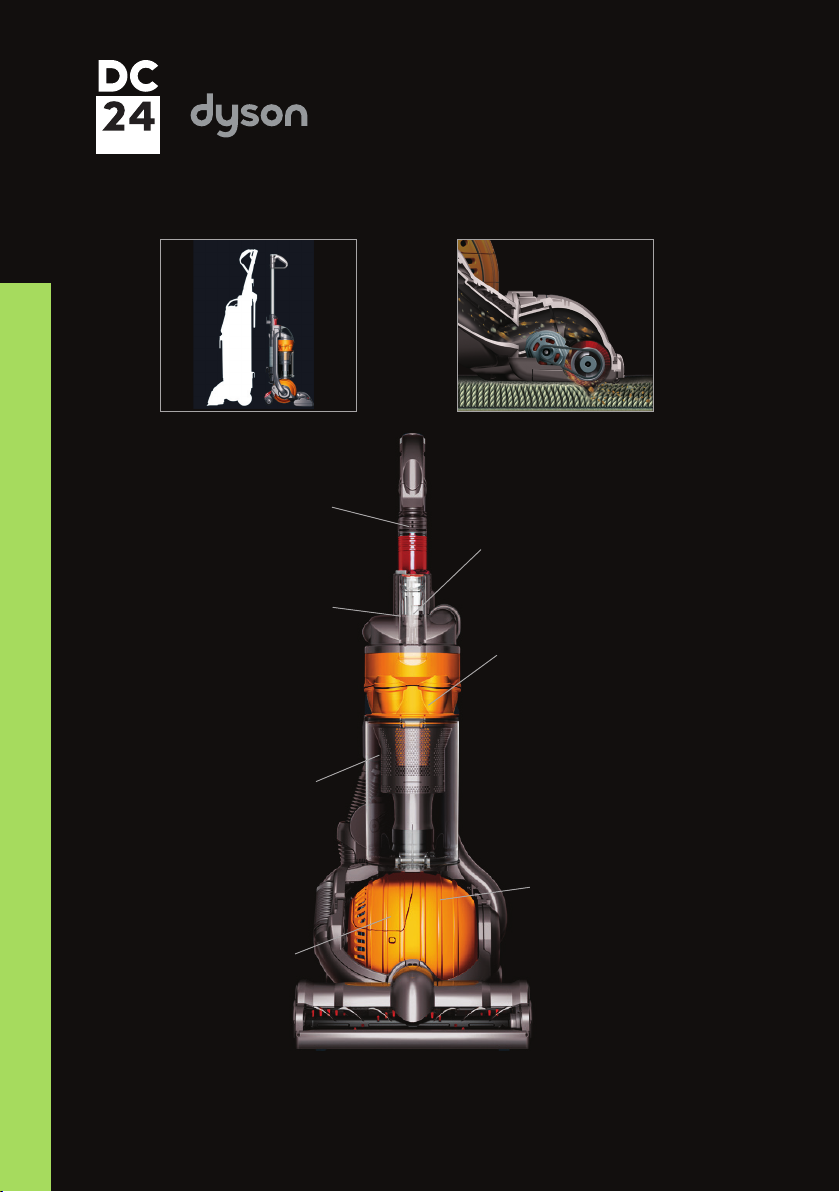
When DC24 is switched on in the upright position, the brushbar motor is off. Tilting the machine into
normal vacuuming mode will automatically operate the upright switch, turning the brushbar motor on.
The brushbar motor can be switched off using the brushbar switch.
The vacuum motor of DC24 is fitted with a heat sensitive Thermal Cut-Out (TCO). This will shut the
motor down for up to 60 minutes if it reaches a temperature >96 degrees celcius. Excessive
temperatures within the motor are usually caused by machine/filter blockages.
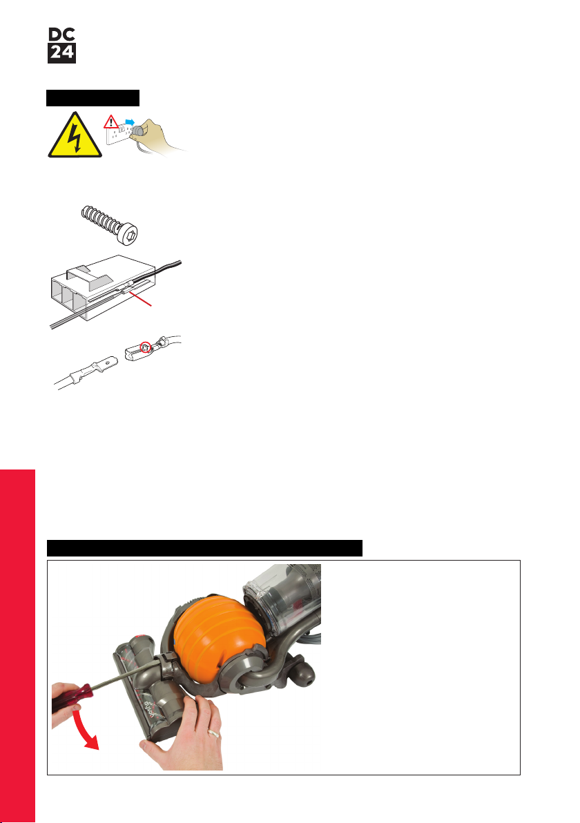
The cleaner head is fitted with a TCO reset switch that will shut the brushbar motor off if it is put under
an excessive load (blocked/seized brushbar etc.). The cause of the shut down should be cleared and
the TCO reset by pressing the switch.
If the cause of the brushbar motor cut-out is not rectified the TCO will repeatedly reactivate, preventing
the brushbar from turning.
Electrical fault diaignosis
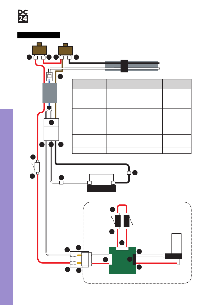
Note: all ‘connection’ numbers and ‘continuity’ checks refer to the illustration and table on page 3.
No machine power (vac motor and brushbar motor off)
1) Check for damage/electrical failure to the plug, fuse and powercord. Check the mechanical
actuation of the on/off switch.
2) Check for a loose connection at points 1, 2, 5 and 6.
3) Test the resistance of the powercord, fuse (UK only), on/off switch and internal powercord (live and
neutral wire only).
No power to the vac motor (brushbar motor on in tilt position)
1) Check connections at points 10 and 11.
2) Test the resistance of the motor cable assembly and vac motor (points 8-9).
3) Check the vac motor brushes, windings, commutator etc. for signs of wear.
No power to the brushbar motor (vac motor on)
1) Ensure the TCO reset button has been pressed.
2) Check connections at points 3, 4, 12, 13, 14, 15, 16, 17, 18, 19, 20, 21 and 22.
3) Check the brushbar motor and PCB assembly for signs of damage/wear.
4) Test the resistance of the brushbar switch (points 3-4), the internal powercord assembly (red wire
only, points 4-12), the upright switch (points 12-13), the yoke loom (points 7-15 and 13-14)
and the cleaner head assembly (points 16-17).
5) Replace the PCB assembly and retest. If the fault is not rectified replace the cleaner head assembly.
Brushbar motor on in upright position (switches off with brushbar switch)
1) Check the mechanical actuation of the upright switch. Ensure the micro switch isn’t jamming or sticking.
Brushbar switch does not switch brushbar motor off in tilt position
1) Check for correct location of the brushbar reset arm (see item 121, page 49).
2) Check the mechanical actuation of the brushbar switch.
3) Test the resistance of the brushbar switch (points 3-4).
Brushbar turns when cleaner head assembly is off the floor (Japanese models only)
1) Check the mechanical actuation of the Jockey wheel.
2) Test the resistance of the TCO reset button/Jockey wheel loom.
3) Replace the PCB assembly and retest. If the fault is not rectified replace the cleaner head assembly.
Electrical fault diagnosis

Fitting notes
Service manual
General notes
Disconnect the machine from the electrical outlet at all
times during repair and test. Failure to do so could result
in electric shock or personal injury.
Some female terminal clips used in DC24 contain a locking
mechanism. The release pip will need to be activated before
separation from the male terminal can occur.
DC24 contains a connector behind the upright switch cover.
To disconnect any wires from it you will have to insert a fine
bladed tool (1mm) to activate the release catch.
All screws used in DC24 are Torx T15 unless otherwise stated.
Motor and yoke assembly replacement - removal
Recommended tools to repair DC24:
Torx T-8, T-10, T-15 screwdrivers
Philips screwdriver
Large flat bladed screwdriver
Terminal screwdriver
1mm flat bladed screwdriver
Long/needle nosed pliers
05
01 Release the c-clip from the top
of the cleaner head assembly.
Wire colours may vary between territories.
Release catch

Fitting notes
Service manual
06
02 Remove the cleaner head
assembly.
03 Remove the four screws from the
ball assembly.
04 Remove the two halves of the ball
assembly.

Fitting notes
Service manual
07
05 Remove the post filter assembly.
06 If it needs replacing the post filter
button can be prised out of the
post filter assembly.
07 To fit, align the button onto the
spring and push firmly into the
retainers.

Fitting notes
Service manual
08
08 If the post filter offering arm needs
replacing carefully release the
spring.
09 With the spring removed firmly
push the post filter offering arm
out of the housing on the motor
bucket.
Fit in reverse.
10 Remove the three long screws in
the upright switch cover.

Fitting notes
Service manual
11 Twist the upright switch cover off
the side of the product.
12 Separate the internal cable
connector.
13 Detach the wire from the lower
terminal of the upright switch.
9

Fitting notes
Service manual
10
16 Remove the long screw behind the
lower duct hose.
15 Firmly pull the lower duct hose off
the side of the product.
14 Remove the long screw next to the
arrow.

Fitting notes
Service manual
11
17 Release the yoke and motor
assemblies from the duct
assembly.
18 Release the yoke wire from the
cable connector.
19 Remove the yoke assembly from
the motor bucket.
Release catch

Fitting notes
Service manual
12
20 If the swivel lock needs replacing
release the catch from the yoke
assembly.
21 With the end released remove the
swivel lock from the middle of the
yoke assembly.
22 To fit, lower the swivel lock onto
the detail on the middle of the
yoke assembly.

Fitting notes
Service manual
23 Ensure when fitting the swivel lock
into the side of the yoke assembly
that the spring locates onto the
side of the peg.
25 Once initially released it can then
be removed by easing it away
from the yoke assembly.
24 If necessary the connector clip can
be removed by initially inserting a
screwdriver into the gap.
13

Fitting notes
Service manual
14
26 To fit, ensure the yoke loom
grommet is positioned in the
connector clip as shown.
28 Align the lugs on the connector
clip with the detail on the yoke
assembly. Rotate the clip to lock
into position.
27 Ensure the yoke loom loops
around the pip detail on the yoke.

Fitting notes
Service manual
15
29 If replacing the motor remove the
motor inlet seal.
30 Remove the bearings from either
end of the motor bucket.
31 Remove the four screws in the
motor bucket.

Fitting notes
Service manual
16
34 Remove the motor from the motor
bucket rear assembly.
33 Remove the motor cable assembly
from the motor bucket front.
32 Separate the two halves of the
motor bucket.

Fitting notes
Service manual
17
35 Detach the motor wires from the
motor cable assembly.
36 Remove the fancase seal and
motor mount from the motor.
37 Remove the motor cable assembly
from the fancase seal if necessary.
Other manuals for DC24 Blueprint Limited Edition
11
Table of contents
Other Dyson Vacuum Cleaner manuals

Dyson
Dyson DC59 Animal User manual

Dyson
Dyson Slim DC18 User manual

Dyson
Dyson DC26 User manual

Dyson
Dyson DCo7 User manual

Dyson
Dyson DC35 MULTI FLOOR User manual

Dyson
Dyson DC 37C User manual

Dyson
Dyson DC 05 User manual

Dyson
Dyson DC14 Telescope Reach User manual

Dyson
Dyson DC 01 User manual

Dyson
Dyson DC26 User manual