E2S GNExB1X05 User manual

INSTRUCTION MANUAL
GNExB1X05
Flameproof Xenon Beacons
For use in Flammable Gas and Dust Atmospheres
_______________________________________________________________________________________________________________________________
European Safety Systems Ltd. Impress House, Mansell Road, Acton, London W3 7QH www.e2s.com Tel: +44 (0)208 743 8880
Document No.D155-00-201-IS Issue 3 28-11-22 Sheet 1 of 5
GNExB1X05
1) Product Table
Ensure the system power supply is capable of providing the maximum current required for all beacons. Review associated cable
size, length and quantity of beacons on each circuit.
2) Warnings
POTENTIAL ELECTROSTATIC CHARGING HAZARD
DO NOT OPEN WHEN AN EXPLOSIVE
ATMOSPHERE IS PRESENT
ALL ENTRIES M20 X 1.5
IF TEMPERATURE EXCEEDS 70ºC AT ENTRY OR 80ºC
AT BRANCHING POINT USE SUITABLE RATED CABLE
AND CABLE GLANDS
3) Marking & Rating Information
All units have a rating label, which carries the following
important information:-
Unit Model.
Voltage Range
Nominal Voltage
Max. Current
See Table 1 for electrical ratings of each Unit Model
3.1) ATEX / IECEx / UKEX Ratings
Standards
EN IEC 60079-0:2018 / IEC60079-0:2017 (Ed 7):
Explosive Atmospheres - Equipment. General Requirements
EN60079-1:2014 / IEC60079-1:2014 (Ed 7):
Explosive Atmospheres - Equipment Protection by Flameproof
Enclosures "d"
EN 60079-31:2014 / IEC 60079-31:2013 (Ed 2):
Explosive Atmospheres - Equipment Dust Ignition Protection by
Enclosure "t"
Ratings
GNExB2:
X05DC012
X05DC024
X05DC048
X05AC115
X05AC230
Ex db IIC Gb T6 Ta -50°C to +40°C
Ex db IIC Gb T5 Ta -50°C to +55°C
Ex db IIC Gb T4 Ta -50°C to +70°C
Ex tb IIIC Db T110°C Ta -50°C to +70°C
Standard Model Nom.
Voltage Voltage Range
Nom.
Operating
Current*
Max
Current
ATEX /
IECEx /
UKEX
GNExB1X05DC012 12Vdc 10-14Vdc 437mA 587mA
GNExB1X05DC024 24Vdc 20-28Vdc 254mA 266mA
GNExB1X05DC048 48Vdc 42-54Vdc 158mA 175mA
GNExB1X05AC115 115Vac 110-125Vac 50/60Hz 95mA 121mA
GNExB1X05AC230 230Vac 220-240Vac 50/60Hz 54mA 88mA
*Rate at 1Hz
The table shows the input current taken by the various beacons.
A supply voltage variation of +/-10% outside the voltage range is permissible.
Nominal current at nominal voltage and 1Hz flash rate.
Max. rated current at worst case supply voltage and flash rate.
Table 1: Electrical Ratings.

_______________________________________________________________________________________________________________________________
European Safety Systems Ltd. Impress House, Mansell Road, Acton, London W3 7QH www.e2s.com Tel: +44 (0)208 743 8880
Document No. D155-00-201-IS Issue 3 28-11-22 Sheet 2 of 5
Certificate No. DEMKO 15ATEX1448X
IECEx UL15.0003X
UL21UKEX2136X
ATEX Mark, Equipment
Group and Category:
II 2G
II 2D
CE Marking and
Notified Body No.
2813
UKCA Marking and
Notified Body No.
0518
4) Zones, Gas Group, Category and Temperature
Classification
The units can be installed in locations with the following
conditions:
Area Classification
Zone 1 Explosive gas air mixture likely to occur in normal
operation.
Zone 2
Explosive gas air mixture not likely to occur in
normal operation, and if it does, it will only exist
for a short time.
Zone 21 Explosive dust air mixture likely to occur in
normal operation.
Zone 22
Explosive dust air mixture not likely to occur in
normal operation, and if it does, it will only exist
for a short time.
Gas Groupings
Group IIA Propane
Group IIB Ethylene
Group IIC Hydrogen and Acetylene
Temperature Classification for Gas Applications
T1 450ºC
T2 300ºC
T3 200ºC
T4 135ºC
T5 100ºC (Up to 55ºC Ambient)
T6 85ºC (Up to 40ºC Ambient)
Dust Groupings
(ATEX
/
IECEx
/
UKEX only)
G
r
oup IIIA Combustible Flyings
Group IIIB Non-conductive Dust
G
r
oup IIIC Conductive Dust
Maximum Surface Temperature for Dust Applications
(
ATEX / IECEx
/
UKEX onl
y)
GNExB2X05 110ºC
E
q
ui
p
ment Cate
g
o
r
y
2G / 2D
Ambient Temperature Range
-50°C to +70°C
IP Rating
IP6X to EN/IEC60079-0
IP66 to EN60529
5) Special Conditions for safe use
The enclosure is non-conducting and may generate an
ignition-capable level of electrostatic charges under certain
extreme conditions. The user should ensure that the
equipment is not installed in a location where it may be
subjected to external conditions that might cause a build-up
of electrostatic charges on non-conducting surfaces.
The stainless steel beacon guard is not earthed and may
generate an ignition-capable level of electrostatic charges. It
has a capacitance of 10pF according to EN/IEC60079-0,
clause 7.5.
The flash dome guard must not be removed from the unit at
any time whilst in service.
All entries must be fitted with a suitable seal at the interface
with enclosure.
6) Product Mounting and Access
6.1. Location and Mounting
The location of the beacons should be made with due regard
to the area over which the warning signal must be visible.
They should only be fixed to services that can carry the
weight of the unit.
The beacons should be securely bolted to a suitable surface
using the 7mm diameter bolt holes in the base of the unit
(see figure 1).
Flashdome
Guard
Flameproof
Lid Moulding
Flameproof
Chamber
External Earth
Stud
Figure 1

_______________________________________________________________________________________________________________________________
European Safety Systems Ltd. Impress House, Mansell Road, Acton, London W3 7QH www.e2s.com Tel: +44 (0)208 743 8880
Document No. D155-00-201-IS Issue 3 28-11-22 Sheet 3 of 5
6.2. Access to the Flameproof Enclosure
In order to connect the electrical supply cables to the beacon
it is necessary to remove the flameproof cover to gain access
to the flameproof chamber. To access the Ex d chamber,
loosen the M3 grub screw on the beacon cover. Open the
enclosure by turning the beacon cover counter-clockwise and
remove the cover taking extreme care not to damage the
flameproof threads in the process (see figure 2).
On completion of the installation the flameproof threaded
joints should be inspected to ensure that they are clean and
that they have not been damaged during installation.
Flameproof threaded joints are not intended to be repaired.
Ensure that the ‘O’ ring seal is in place and undamaged.
When fitting the flameproof cover ensure the thread is
engaged correctly. Fully tighten the cover all the way, ensure
no gap is visible between the cover and base of the beacon
enclosure. Tighten the M3 grub screw.
7) Installation Requirements
7.1. Installation Standards Compliance
Attention: Disconnect from power
source before installation or service
to prevent electric shock.
The beacons must only be installed by suitably qualified
personnel in accordance with the latest issues of the relevant
standards:
EN60079-14 / IEC60079-14: Explosive atmospheres -
Electrical installations design, selection and erection.
EN60079-10-1 / IEC60079-10-1: Explosive atmospheres -
Classification of areas. Explosive gas atmospheres.
EN60079-10-2 / IEC60079-10-2: Explosive atmospheres -
Classification of areas. Explosive dust atmospheres.
The installation of the units must also be in accordance with
any local codes that may apply and should only be carried
out by a competent electrical engineer who has the
necessary training.
7.2. Cable Selection and Connections
When selecting the cable size, consideration must be given
to the input current that each unit draws, the number of
beacons on the line and the length of the cable runs. The
cable size selected must have the necessary capacity to
provide the input current to all of the beacons connected to
the line.
Electrical connections are to be made into the terminal blocks
on the PCBA. A five-way terminal block is provided on both
AC and DC beacons. There are two live, two neutral and an
Earth terminal for the input and output wiring on AC units. DC
units have two +ve, two -ve and an S2 terminal for the input
and output wiring.
Wires having a cross sectional area of up to 2.5mm² can be
connected to each terminal way. If an input and output wire is
required the 2-off Live/Neutral or +/- terminals can be used. If
fitting 2-off wires to one terminal way the sum of the 2-off
wires must be a maximum cross sectional area of 2.5mm².
Strip wires to 8mm. When connecting wires to the terminals
great care should be taken to dress the wires so that when
the cover is inserted into the chamber the wires do not exert
excess pressure on the terminal blocks. This is particularly
important when using cables with large cross sectional areas
such as 2.5mm².
Earthing
Please note that for AC supply voltage product versions the
Earth terminal on the PCBA does not provide an earth
connection to the product enclosure. The enclosure must be
independently earthed using either the external or internal
earth fixing point, (see fig 3 and notes below).
Both AC and DC beacon units can be connected to an earth.
The units are provided with internal and external earth
terminals which are both located on the terminal chamber
section of the unit (see figures 3 and 4).
M3 x 6mm Grub Screw
Lid Moulding
Figure 2
O-Ring
Supply
Terminals
E
L
L
N
AC Unit
Figure 3
N
External Earth Stud Internal Earth Stud
S2
--++
DC Unit
External Earth Stud Internal Earth Stud Supply Terminals
Figure 4

_______________________________________________________________________________________________________________________________
European Safety Systems Ltd. Impress House, Mansell Road, Acton, London W3 7QH www.e2s.com Tel: +44 (0)208 743 8880
Document No. D155-00-201-IS Issue 3 28-11-22 Sheet 4 of 5
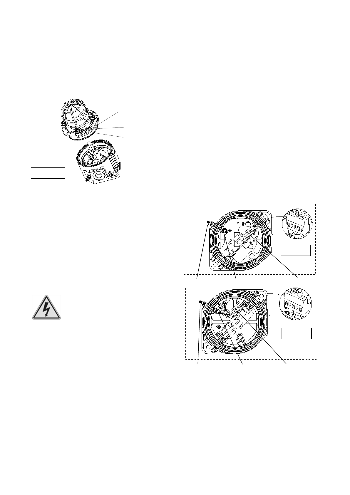
Internal earthing connections on AC units should be made to
the Internal Earth terminal on the PCBA. The earth conductor
should be at least equal in size and rating to the incoming
power conductors.
External earthing connections should be made to the M4
earth stud, using a ring crimp terminal to secure the earth
conductor to the earth stud between the two M4 stainless
steel flat washers, then reassemble the M4 spring washer
and tighten the M4 nut to ensure that the cable lug is secured
against loosening and twisting. The external earth conductor
should be at least 4mm2 in size.
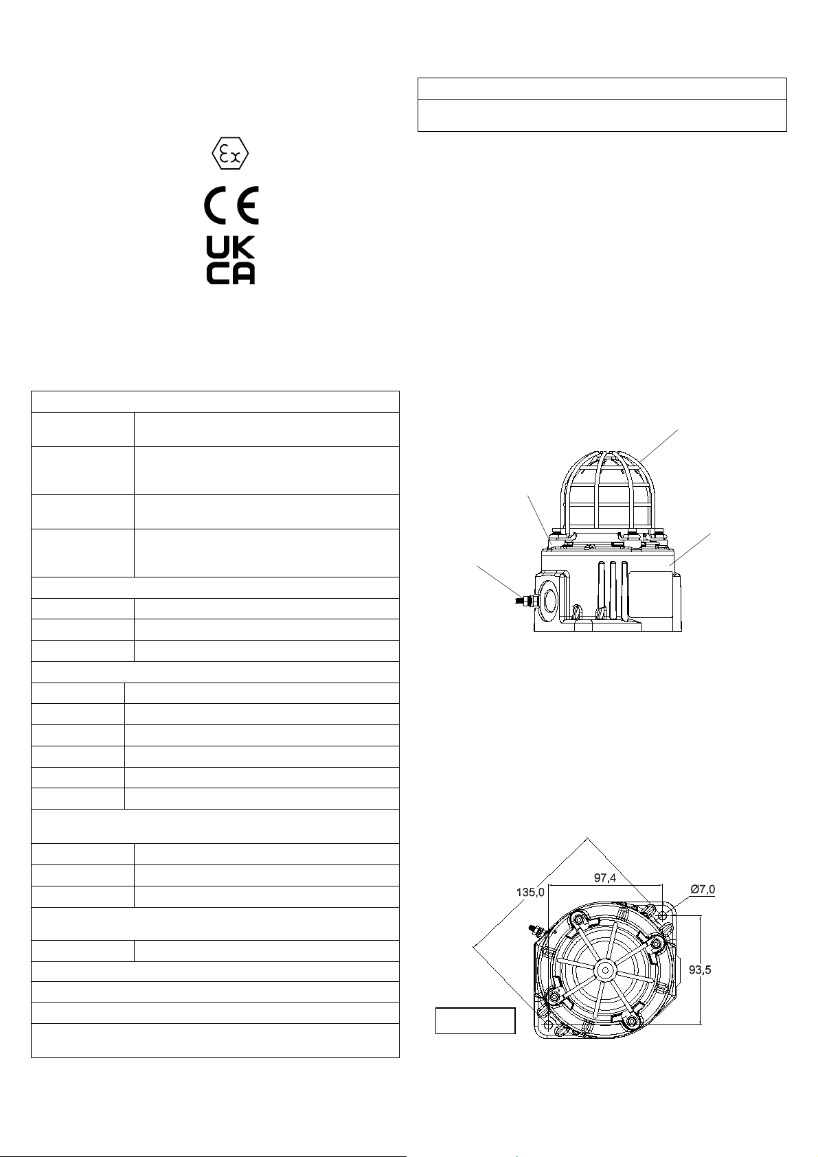
7.3. Cable Glands, Blanking Elements and Adapters
The cable entry temperature may exceed +70ºC or the cable
branching point temperature may exceed 80ºC at high
ambient temperatures and therefore suitable heat resisting
cables and cable glands must be used, rated 80°C for
ambient temperatures of 55°C and rated 95°C for ambient
temperatures of 70°C.
Cable Glands
The cable gland entries have an M20 x 1.5 entry thread. Only
suitably rated and ATEX / IECEx / UKEX certified cable
glands which must be suitable for the type of cable being
used.
Blanking Plugs
When only one cable entry is used the other entry must be
closed with suitably rated and ATEX / IECEx / UKEX certified
blanking plugs.
For combustible dust applications, the cable entry device and
blanking elements shall be in type of explosion protection and
shall have an IP 6X rating.
Ingress Protection
If a high IP (Ingress Protection) rating is required then a
suitable sealing washer must be fitted under the cable glands
or blanking plugs.
A minimum ingress protection rating of IP6X must be
maintained for installations in explosive dust atmospheres.
Adapters
The GNEx Beacon Range can be supplied with the following
types of adapters:
M20 to ½” NPT
M20 to ¾” NPT
M20 to M25
It is important to note that stopping plugs cannot be fitted
onto adapters, only directly onto the M20 entries.
Any other adapters used must be suitably rated as per the
applicable standards.
If the installation is made using conduit, openings must have
a sealing fitting connected as close as practical to the wall of
the enclosure, but in no case more than the size of the
conduit or 50mm, whichever is the lesser.
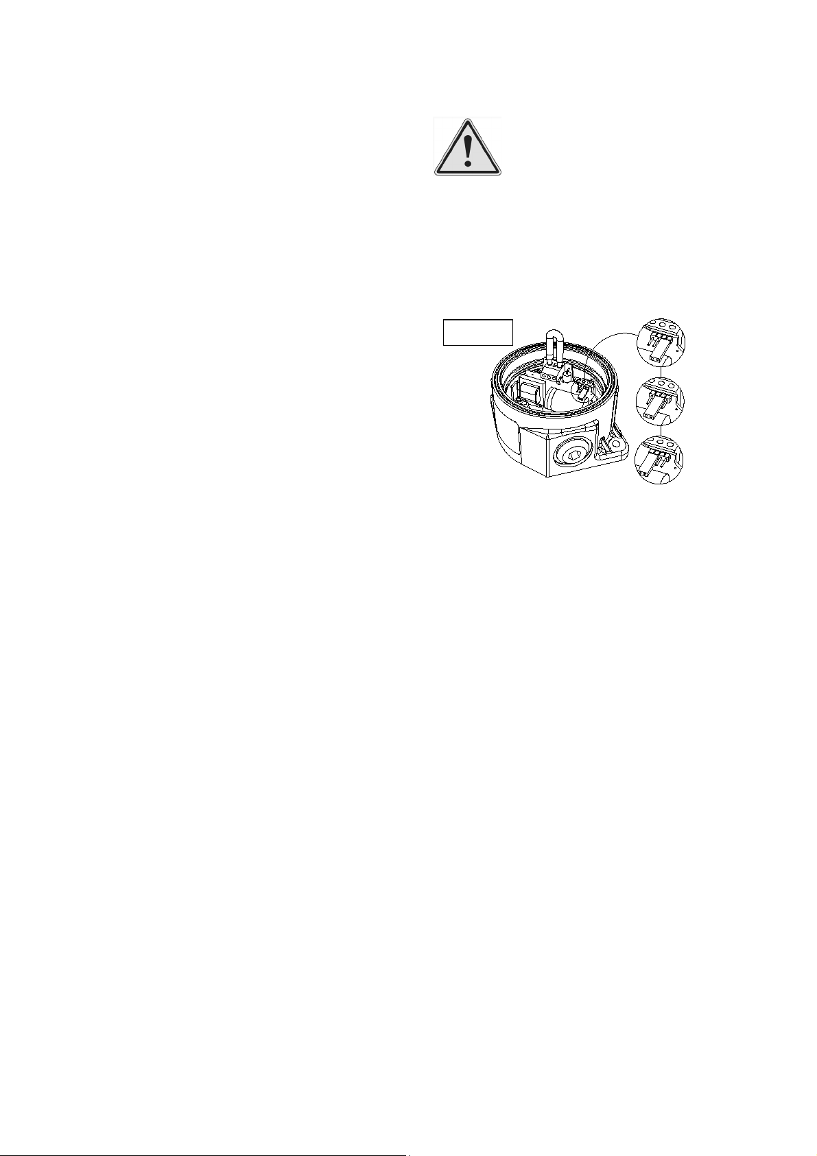
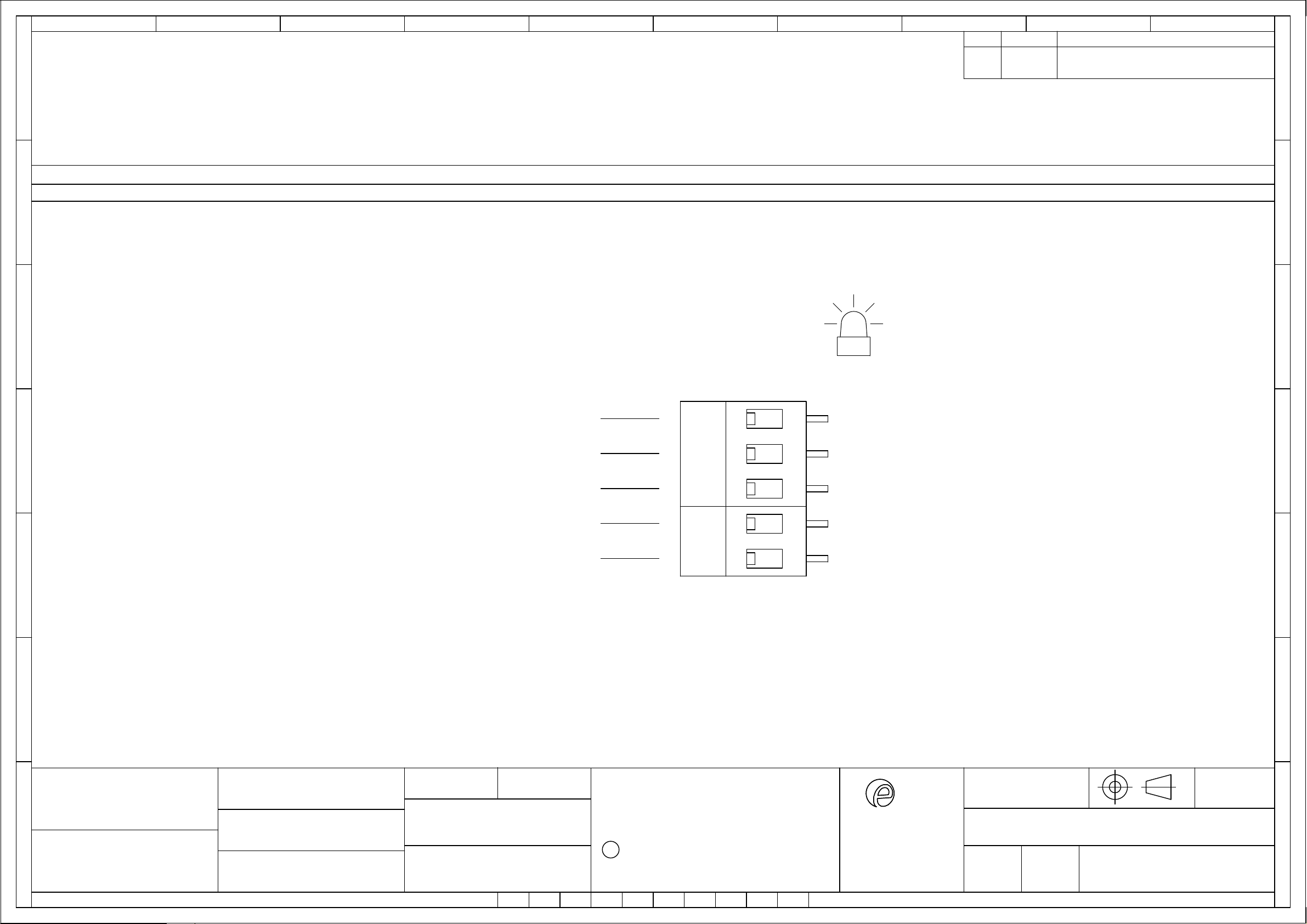
8) Flash Patterns (DC Units Only)
The GNExB1X05 DC beacons can produce three different
flash patterns as listed below. The flash patterns are set
internally by the selection of pin headers. The flash pattern
set can be changed externally to produce a second stage by
connecting terminal S2 to –ve supply line whilst powering the
+ve and –ve supply terminals.
The AC Beacons only flash at 1Hz.
Stage 1 Stage 2
1Hz Double Strike
1.5Hz Double Strike
Double Strike Double Strike
Synchronised Operation
All GNExBG1X05 beacons that are connected to the same
supply line will have a synchronised flash rate at one flash
every second. To ensure that the units will be synchronised
check that the pin header is set to 1Hz (see Figure 5).
9) End of Line Monitoring (DC Units)
On the GNExBG1X05 DC beacons, dc reverse line monitoring
can be used if required. All DC units have a blocking diode
fitted in their supply input lines. An end of line monitoring
diode or an end of line monitoring resistor can be connected
across the +ve and –ve terminals in the flameproof chamber.
If an end of line resistor is used it must have a minimum
resistance value of 3k3 ohms and a minimum wattage of
0.5W or a minimum resistance value of 500 ohms and a
minimum wattage of 2W.
10) Maintenance, Overhaul and Repair
Maintenance, repair and overhaul of the equipment should
only be carried out by suitably qualified personnel in
accordance with the current relevant standards:
EN60079-19/IEC60079-19 Explosive atmospheres - Equipment
repair, overhaul and reclamation
EN60079-17/IEC60079-17 Explosive atmospheres - Electrical
installations inspection and maintenance
Units must not be opened while an explosive atmosphere is
present.
Electrostatic charging hazard - Clean only with a damp cloth.
Figure 5
1.5Hz
1 Hz
Double
Strike
Warning – high-intensity light source. Avoid
looking directly at the light source for
extended periods of time.

_______________________________________________________________________________________________________________________________
European Safety Systems Ltd. Impress House, Mansell Road, Acton, London W3 7QH www.e2s.com Tel: +44 (0)208 743 8880
Document No. D155-00-201-IS Issue 3 28-11-22 Sheet 5 of 5
1SIL 2 Reliability Data
Reliability and Functional safety IEC/EN61508 which has
been assessed and is considered suitable for use in low
demand safety function:
1. Random Hardware Failures and Architectural constraints
(route 2H).
2. As an unvoted item (i.e. hardware fault tolerance of 0) at
SIL 2.
The product was assessed against failure modes:
Failure respond to an input by lighting a beacon.
Spurious light output despite no input.
3. When employing the device in a SIL2 compliant system
the user should ensure frequent or continuous automatic
monitoring of continuity.
Integrity in respect of failure to function SIL2 & SIL1
Total Failure rate 0.48 pmh
“Hazardous” failure rate (revealed) 0 pmh
“Hazardous” failure rate (unrevealed) 0.48 pmh
“Safe” failure rate (revealed) 0 pmh
“Safe” failure rate (unrevealed) 0
System type B
Hardware Fault Tolerance 0
Dia
g
nostic Covera
g
e >60%
PFD (hazardous failure) 2.1 x 10⁻³
Proof Test Interval Up to 1 yea
r

warning signals
2S
EUROPEAN SAFETY SYSTEMS LTD
IMPRESS HOUSE
MANSELL ROAD
ACTON
LONDON W3 7QH
WWW.E2S.COM
C
THIS DRAWING AND ANY INFORMATION OR DESCRIPTIVE
MATTER THEREIN IS COMMUNICATED IN CONFIDENCE AND
IS THE COPYRIGHT PROPERTY OF EUROPEAN SAFETY
SYSTEMS LTD. NEITHER THE WHOLE OR ANY EXTRACT MAY
BE DISCLOSED, LOANED, COPIED OR USED FOR
MANUFACTURING OR TENDERING PURPOSES WITHOUT THEIR
WRITTEN CONSENT.
EUROPEAN SAFETY SYSTEMS LTD.
AS PER LATEST DATE OF ISSUE SHOWN ABOVE
DRAWING TO BS8888:2000
GEOMETRIC TOLERANCES TO ISO1101:1983
LINEAR DIMENSIONAL TOLS
ANGULAR DIMENSIONAL TOLS
STANDARDS
MOD No. REASON - INITIAL - DATEISSUE
DATE
APPROVED
CHECKED DATE
DATE
DRAWN WEIGHT (Kg)
SURFACE FINISH
MATERIAL
ALTERNATIVE MATERIAL SHEETSCALE
TITLE
A3
IF IN DOUBT, ASK -
DO NOT SCALE
ALL DIMENSIONS IN MM
DRAWING NUMBER
A
B
C
D
E
F
G
109
G
F
E
78
6
5
D
C
134
2
A
B
D155-06-201
R.N.POTTS OF
GNExB1 X05
NTS 1 2
GNExB1 BEACONS
R.N.POTTS
R. RAIT
BEACON WIRING DIAGRAMS
+ve IN
+ve OUT
-ve IN
-ve OUT
R1
+
+
-
-
DC XENON GNExB1X05 UNITS
Line Monitoring
Power: +ve & -ve
OPTIONAL LINE MONITORING RESISTOR, CUSTOMER SUPPLIED,
RECOMMENDED MINIMUM VALUES:
R1
500Ω MIN, 2W MIN OR 3K3Ω MIN, 0.5W MIN
28/11/22
28/11/22
28/11/22
C
New Format
RSR 29/11/22
S2 S2

warning signals
2S
EUROPEAN SAFETY SYSTEMS LTD
IMPRESS HOUSE
MANSELL ROAD
ACTON
LONDON W3 7QH
WWW.E2S.COM
C
THIS DRAWING AND ANY INFORMATION OR DESCRIPTIVE
MATTER THEREIN IS COMMUNICATED IN CONFIDENCE AND
IS THE COPYRIGHT PROPERTY OF EUROPEAN SAFETY
SYSTEMS LTD. NEITHER THE WHOLE OR ANY EXTRACT MAY
BE DISCLOSED, LOANED, COPIED OR USED FOR
MANUFACTURING OR TENDERING PURPOSES WITHOUT THEIR
WRITTEN CONSENT.
EUROPEAN SAFETY SYSTEMS LTD.
AS PER LATEST DATE OF ISSUE SHOWN ABOVE
DRAWING TO BS8888:2000
GEOMETRIC TOLERANCES TO ISO1101:1983
LINEAR DIMENSIONAL TOLS
ANGULAR DIMENSIONAL TOLS
STANDARDS
MOD No. REASON - INITIAL - DATEISSUE
DATE
APPROVED
CHECKED DATE
DATE
DRAWN WEIGHT (Kg)
SURFACE FINISH
MATERIAL
ALTERNATIVE MATERIAL SHEETSCALE
TITLE
A3
IF IN DOUBT, ASK -
DO NOT SCALE
ALL DIMENSIONS IN MM
DRAWING NUMBER
A
B
C
D
E
F
G
109
G
F
E
78
6
5
D
C
134
2
A
B
D155-06-201
R.N.POTTS OF
GNExB1 X05
NTS 2 2
GNExB1 BEACONS
R.N.POTTS
R. RAIT 28/11/22
BEACON WIRING DIAGRAMS
AC XENON GNExB1 X05 UNITS
Power: Live & Neutral
Neutral IN
Neutral OUT
Live IN
Live OUT
N
N
L
L
E
Earth
28/11/22
28/11/22
C
New Format
RSR 29/11/22

E2STelephone:+44(0)2087438880Fax:+44(0)2087404200Email:[email protected]www.e2s.comDC‐037_Issue_H(GNExB,GNExJ).docx‐Page1of2‐
QAF_252_Issue_5
EUDeclarationofConformity
Manufacturer: EuropeanSafetySystemsLtd.
ImpressHouse,MansellRoad,Acton
London,W37QH
UnitedKingdom
AuthorisedRepresentative:E2SWarnsignaltechnikUG
Charlottenstrasse45‐51
72764Reutlingen
Germany
EquipmentType: GNExB1X05
GNExB2X05,GNExB2X10,GNExB2X15,GNExB2X21
GNExB2LD2
GNExJ2
Directive2014/34/EU:EquipmentandProtectiveSystemsforuseinPotentiallyExplosiveAtmospheres(ATEX)
NotifiedBodyforEUtypeExamination(ModuleB):ULInternationalDemkoA/S
NotifiedBodyNo.:0539
Borupvang5A,2750Ballerup,Denmark
EU‐typeExaminationCertificate(ModuleB):DEMKO15ATEX1448X
NotifiedBodyforQualityAssuranceNotification/ConformitytoEU‐type
basedon
qualityassuranceoftheproductionprocess(ModuleD):
SiraCertificationService
NotifiedBodyNo.:2813
CSAGroupNetherlandsB.V,Utrechtseweg310,6812AR,Arnhem,Netherlands
QualityAssuranceNotification(ModuleD):SIRA05ATEXM342
Provisionsfulfilledbytheequipment:II2GExdbIICT4…T6Gb
II2DExtbIIICT80°C…T138°CDb
IP6XDustProtectiontoEN60079‐0/EN60079‐31
Standardsapplied:ENIEC60079‐0:2018
EN60079‐1:2014
EN60079‐31:2014
Directive2014/30/EU:ElectromagneticCompatibilityDirective(EMC)
Standardsapplied:EN61000‐6‐1:2007
EN61000‐6‐2:2005
EN61000‐6‐3:2007/A1:2011/AC:2012
EN61000‐6‐4:2007/A1:2011
Directive2011/65/EU:Restrictionoftheuseofcertainhazardoussubstancesinelectricalandelectronicequipment(RoHS)
Theproductandallthecomponentscontainedwithinitareinaccordancewiththerestrictionoftheuseofhazardoussubstancesinelectricalandelectronic
equipment,includingamendmentbyDirective2015/863/EU.
Regulation(EC)1907/2006:Registration,Evaluation,AuthorisationandRestrictionofChemicals(REACH)
Theproductandallthecomponentscontainedwithinitarefreefromsubstancesofveryhighconcern.
OtherStandardsandRegulations
EN60529:1992+A2:2013‐Degreesofprotectionprovidedbyenclosures(IPcode)–enclosureratedIP66/67

E2STelephone:+44(0)2087438880Fax:+44(0)2087404200Email:[email protected]www.e2s.comDC‐037_Issue_H(GNExB,GNExJ).docx‐Page2of2‐
QAF_252_Issue_5
MartinStreetzDocumentNo.:DC‐037_Issue_H
QualityAssuranceManagerDateandPlaceofIssue:London,03/12/2021
EUDeclarationofConformity
OnbehalfofEuropeanSafetySystemsLtd.,Ideclarethat,onthedatetheequipmentaccompaniedbythisdeclarationisplacedonthemarket,theequipment
conformswithalltechnicalandregulatoryrequirementsoftheabovelisteddirectives,regulationsandstandards.
ThisDeclarationisissuedunderthesoleresponsibilityofthemanufacturer.

E2S Telephone: +44 (0)20 8743 8880 Fax: +44 (0)20 8740 4200 Email: sal[email protected] www.e2s.com DC-098_Issue_A (GNExB, GNExJ UKCA).docx - Page 1 of 2 -
QAF_252_Issue_5
UKCA Declaration of Conformity
Manufacturer: European Safety Systems Ltd.
Impress House, Mansell Road, Acton
London, W3 7QH
United Kingdom
Equipment Type: GNExB1X05
GNExB2X05, GNExB2X10, GNExB2X15, GNExB2X21
GNExB2LD2
GNExJ2
Directive UKSI 2016:1107 (as amended by UKSI 2019:696) – Schedule 3A, Part 1 : Product or Protective System Intended for use in Potentially Explosive Atmospheres
(UKCA)
Notified Body for
UK
type Examination
(Module B)
:
UL International (UK) Ltd
Notified Body No.: 0843
Unit 1-3 Horizon Kingsland Business Park, Wade Road,
Basingstoke, Hampshire RG24 8AH UK
UK
-
type Examination Certificate
(Module B)
:
UL21UKEX2136X
Notified Body for Quality Assurance Notification
/
Conformity to EU
-
type
based on
quality assurance of the production process (Module D):
Sira Certification Service
Notified Body No.: 0518
Rake Lane, Eccleston, Chester CH4 9JN, UK
Quality Assurance Notification
(Module D)
:
CSAE 22UKQAN0046
Provisions fulfilled by the equipment:
II 2G
Ex db
IIC T4…T6
Gb
II 2D Ex tb IIIC T80°C…T138°C Db
IP6X Dust Protection to EN60079-0 / EN60079-31
Standards applied:
EN
IEC
60079
-
0:201
8
EN 60079-1: 2014
EN 60079-31: 2014
Directive 2014/30/EU: Electromagnetic Compatibility Directive (EMC)
Standards applied:
EN 61000
-
6
-
1:2007
EN 61000-6-2:2005
EN 61000-6-3:2007 / A1:2011 / AC: 2012
EN 61000-6-4:2007 / A1: 2011
Directive 2011/65/EU: Restriction of the use of certain hazardous substances in electrical and electronic equipment (RoHS)
The product and all the components contained within it are in accordance with the restriction of the use of hazardous substances in electrical and electronic
equipment, including amendment by Directive 2015/863/EU.
Regulation (EC) 1907/2006: Registration, Evaluation, Authorisation and Restriction of Chemicals (REACH)
The product and all the components contained within it are free from substances of very high concern.
Other Standards and Regulations
EN 60529:1992+A2:2013 - Degrees of protection provided by enclosures (IP code) – enclosure rated IP66/67

E2S Telephone: +44 (0)20 8743 8880 Fax: +44 (0)20 8740 4200 Email: sal[email protected] www.e2s.com DC-098_Issue_A (GNExB, GNExJ UKCA).docx - Page 2 of 2 -
QAF_252_Issue_5
Martin Streetz Document No.: DC-098_Issue_A
Quality Assurance Manager Date and Place of Issue: London, 24/02/2022
UKCA Declaration of Conformity
On behalf of European Safety Systems Ltd., I declare that, on the date the equipment accompanied by this declaration is placed on the market, the equipment
conforms with all technical and regulatory requirements of the above listed directives, regulations and standards.
This Declaration is issued under the sole responsibility of the manufacturer.

Page left Intentionally blank
This manual suits for next models
5
Table of contents
Other E2S Lighting Equipment manuals

E2S
E2S AlertAlight AL121H User manual

E2S
E2S BExBG21D-P User manual

E2S
E2S STExB2X05 User manual

E2S
E2S BExBGL2D-P User manual

E2S
E2S BExBG21D User manual

E2S
E2S MC1LD2FDC024 User manual

E2S
E2S BExTBG05D-P User manual

E2S
E2S IS-L101L User manual

E2S
E2S Spectra H100 TF User manual

E2S
E2S BExBG10D-P User manual