E2S STExB2X05 User manual

INSTRUCTION MANUAL
STExB2X05, STExB2X10, STExB2X15 & STExB2X21
Flameproof Xenon Beacons
For use in Flammable Gas and Dust Atmospheres
E2S Warning Signals Impress House, Mansell Road, Acton, London W3 7QH www.e2s.com
Tel: +44 (0)208 743 8880
Document No. D199-00-201-IS
Issue 5
28-11-22 Sheet 1 of 8
STExB2X05
STExB2X10
STExB2X15
STExB2X21
1) Product Table
Ensure the system power supply is capable of providing the maximum current required for all beacons. Review associated cable size,
length and quantity of beacons on each circuit.
Standard Model Nom.
Voltage Voltage Range
Nom.
Operating
Current*
Max Current
ATEX / IECEx / UKEx /
NEC / CEC
STExB2X05DC012 12Vdc 12-14Vdc 585mA 600mA
STExB2X05DC024 24Vdc 20-28Vdc 295mA 350mA
STExB2X05DC048 48Vdc 42-54Vdc 145mA 150mA
STExB2X05AC115 115Vac 110-120Vac 50/60Hz 140mA 200mA
STExB2X05AC230 230Vac 220-240Vac 50/60Hz 70mA 100mA
STExB2X10DC024 24Vdc 20-28Vdc 605mA 710mA
STExB2X10DC048 48Vdc 42-54Vdc 230mA 250mA
STExB2X10AC115 115Vac 110-120Vac 50/60Hz 220mA 300mA
STExB2X10AC230 230Vac 220-240Vac 50/60Hz 130mA 180mA
ATEX / IECEx / UKEx
STExB2X15DC024 24Vdc 20-28Vdc 835mA 920mA
STExB2X15DC048 48Vdc 42-54Vdc 330mA 360mA
STExB2X15AC115 115Vac 110-120Vac 50/60Hz 310mA 420mA
STExB2X15AC230 230Vac 220-240Vac 50/60Hz 170mA 230mA
STExB2X21DC024 24Vdc 20-28Vdc 1130mA 1240mA
STExB2X21DC048 48Vdc 42-54Vdc 530mA 560mA
STExB2X21AC115 115Vac 110-120Vac 50/60Hz 500mA 530mA
STExB2X21AC230 230Vac 220-240Vac 50/60Hz 195mA 270mA
*Rate at 1Hz
The table shows the input current taken by the various beacons.
Nominal current at nominal voltage and 1Hz flash rate.
Max. rated current at worst case supply voltage and flash rate.
Table 1: Electrical Ratings.

E2S Warning Signals Impress House, Mansell Road, Acton, London W3 7QH www.e2s.com
Tel: +44 (0)208 743 8880
Document No. D199-00-201-IS
Issue 5
28-11-22 Sheet 2 of 8
2) Warnings
DO NOT OPEN WHEN AN EXPLOSIVE ATMOSPHERE IS
PRESENT.
POTENTIAL ELECTROSTATIC CHARGING HAZARD –
CLEAN ONLY WITH A DAMP CLOTH.
ALL ENTRIES M20 X 1.5MM.
USE SUITABLE RATED CABLES AND CABLE GLANDS
IF TEMPERATURE EXCEEDS AS PER STANDARDS
INDICATIONS BELOW.
FOR ATEX / IECEx & UKEx STANDARDS:
70ºC AT ENTRY OR 80ºC AT BRANCHING POINT.
FOR NEC / CEC STANDARDS:
60ºC AT ENTRY OR 60ºC AT BRANCHING POINT.
3) Marking & Rating Information
All units have a rating label, which carries the following
important information:
Unit Model.
Voltage Range
Nominal Voltage
Max. Current
See Table 1 for electrical ratings of each Unit Model.
3.1. ATEX / IECEx & UKEx Ratings
Standards
EN IEC 60079-0:2018 / IEC60079-0:2017 (Ed 7):
Explosive Atmospheres - Equipment. General Requirements
EN60079-1:2014 / IEC60079-1:2014 (Ed 7):
Explosive Atmospheres - Equipment Protection by Flameproof
Enclosures "d"
BS EN 60079-31:2014 / IEC 60079-31:2013 (Ed 2):
Explosive Atmospheres - Equipment Dust Ignition Protection by
Enclosure "t"
Ratings
STExB2:
X05DC012
X05DC024
X05DC048
Ex db IIC T5 Gb Ta -50°C to +70°C
Ex db IIC T6 Gb Ta -50°C to +55°C
Ex tb IIIC T92°C Db Ta -50°C to +70°C
STExB2:
X05AC115
X05AC230
Ex db IIC T4 Gb Ta -50°C to +70°C
Ex db IIC T5 Gb Ta -50°C to +55°C
Ex db IIC T6 Gb Ta -50°C to +40°C
Ex tb IIIC T110°C Db Ta -50°C to +70°C
STExB2:
X10DC024
X10DC048
Ex db IIC T4 Gb Ta -50°C to +70°C
Ex db IIC T5 Gb Ta -50°C to +45°C
Ex tb IIIC T118°C Db Ta -50°C to +70°C
STExB2:
X10AC115
X10AC230
Ex db IIC T4 Gb Ta -50°C to +70°C
Ex tb IIIC T128°C Db Ta -50°C to +70°C
STExB2:
X15DC024
X15DC048
Ex db IIC T4 Gb Ta -50°C to +70°C
Ex tb IIIC T127°C Db Ta -55°C to +70°C
STExB2:
X15AC115
X15AC230
Ex db IIC T3 Gb Ta -50°C to +70°C
Ex db IIC T4 Gb Ta -50°C to +65°C
Ex tb IIIC T131°C Db Ta -55°C to +70°C
STExB2:
X21DC024
X21DC048
Ex db IIC T3 Gb Ta -50°C to +70°C
Ex db IIC T4 Gb Ta -50°C to +65°C
Ex tb IIIC T131°C Db Ta -50°C to +70°C
STExB2:
X21AC115
X21AC230
Ex db IIC T3 Gb Ta -50°C to +65°C
Ex db IIC T4 Gb Ta -50°C to +55°C
Ex tb IIIC T137°C Db Ta -50°C to +65°C
Certificate No. DEMKO 16 ATEX1466X
IECEx ULD 16.0017X
UL21UKEX2019X
ATEX Mark, Equipment
Group and Category:
II 2G
II 2D
CE Marking and
Notified Body No.
2813
UKCA Marking and
Notified Body No.
0518
3.2. NEC / CEC Ratings
All models are approved for use as Visual Signal Device for
use as General Signalling:
UL1638A & CSA C22.2 No 205-17
NEC Class / Zone Ratings US Codes
Standards
UL 60079-0 (Ed. 7) 04/15/2020
Explosive Atmospheres - part 0: Equipment - General
Requirements
UL 60079-1 (Ed. 7) 2015
Explosive Atmospheres - Part 1: Equipment Protection by
Flameproof Enclosures 'd'
Ratings
STExB2:
X05DC012
X05DC024
X05DC048
Class I Zone 1 AEx db IIC T5 Gb Ta -50°C to +70°C
Class I Zone 1 AEx db IIC T6 Gb Ta -50°C to +55°C
STExB2:
X05AC115
X05AC230
Class I Zone 1 AEx db IIC T4 Gb Ta -50°C to +70°C
Class I Zone 1 AEx db IIC T5 Gb Ta -50°C to +55°C
Class I Zone 1 AEx db IIC T6 Gb Ta -50°C to +40°C
STExB2:
X10DC024
X10DC048
Class I Zone 1 AEx db IIC T4 Gb Ta -50°C to +70°C
Class I Zone 1 AEx db IIC T5 Gb Ta -50°C to +45°C
STExB2:
X10AC115
X10AC230
Class I Zone 1 AEx db IIC T4 Gb Ta -50°C to +70°C
Installation must be carried out in compliance with the National
Electric Code.

E2S Warning Signals Impress House, Mansell Road, Acton, London W3 7QH www.e2s.com Tel: +44 (0)208 743 8880
Document No. D199-00-201-IS Issue 5 28-11-22 Sheet 3 of 8
CEC Class / Zone Ratings Canada
Standards
CAN/CSA C22.2 No. 60079-0 (Ed. 4) 02/2019
Explosive Atmospheres - Part 0: Equipment - General
Requirements
CAN/CSA C22.2 No. 60079-1 (Ed. 3) 2016
Electrical Apparatus for Explosive Gas Atmospheres - Part 1:
Flameproof Enclosures 'd'
Rating
STExB2:
X05DC012
X05DC024
X05DC048
Ex db IIC T5 Gb Ta -50°C to +70°C
Ex db IIC T6 Gb Ta -50°C to +55°C
STExB2:
X05AC115
X05AC230
Ex db IIC T4 Gb Ta -50°C to +70°C
Ex db IIC T5 Gb Ta -50°C to +55°C
Ex db IIC T6 Gb Ta -50°C to +40°C
STExB2:
X10DC024
X10DC048
Ex db IIC T4 Gb Ta -50°C to +70°C
Ex db IIC T5 Gb Ta -50°C to +45°C
STExB2:
X10AC115
X10AC230
Ex db IIC T4 Gb Ta -50°C to +70°C
Installation must be carried out in compliance with the
Canadian Electric Code.
NEC & CEC Class / Division Ratings for US / Canada,
USL CNL
Standards
STExB2X
Xenon
beacons
UL1638A (Ed. 1) 2016
Standard for Visual Signal Appliances for General
Signalling Use
CSA C22.2 No. 205-17 (Ed. 3) 2017
Signal Equipment
Ratings
STExB2:
X05DC012
X05DC024*
X05DC048
Class I Div 2 Group ABCD T5 Ta -50°C to +70°C
Class I Div 2 Group ABCD T6 Ta -50°C to +55°C
STExB2:
X05AC115
X05AC230
Class I Div 2 Group ABCD T4 Ta -50°C to +70°C
Class I Div 2 Group ABCD T5 Ta -50°C to +55°C
Class I Div 2 Group ABCD T6 Ta -50°C to +40°C
STExB2:
X10DC024*
X10DC048
Class I Div 2 Group ABCD T4 Ta -50°C to +70°C
Class I Div 2 Group ABCD T5 Ta -50°C to +45°C
STExB2:
X10AC115
X10AC230
Class I Div 2 Group ABCD T4 Ta -50°C to +70°C
*SIL Suitable
The certification approval has validated continuous use up to
38°C ambient and are for transient use up to 70°C ambient.
Installation must be carried out in compliance with the National
Electric Code / Canadian Electric Code.
p
4) Zones, Gas Group, Category and
Temperature Classification
The units can be installed in locations with the following
conditions:
A
rea Classification
Zone 1 Explosive gas air mixture likely to occur in normal
operation.
Zone 2
Explosive gas air mixture not likely to occur in
normal operation, and if it does, it will only exist
for a short time.
Zone 21
(ATEX / IECEx &
UKEx only)
Explosive dust air mixture likely to occur in
normal operation.
Zone 22
(ATEX / IECEx &
UKEx only)
Explosive dust air mixture not likely to occur in
normal operation, and if it does, it will only exist
for a short time.
Gas Groupings
Group IIA Propane
Group IIB Ethylene
Group IIC Hydrogen and Acetylene
Temperature Classification for Gas Applications
T1 450ºC
T2 300ºC
T3
200ºC
(STExB2X15AC & STExB2X21DC up to 70°C
ambient; STExB2X21AC up to 65°C ambient)
T4
135ºC
(STExB2X05AC, STExB2X10DC, STExB2X10AC
& STExB2X15DC up to 70°C ambient;
STExB2X15AC & STExB2X21DC up to 65°C
ambient;
STExB2X21AC up to 55°C ambient)
T5
100ºC
(STExB2X05DC up to 70°C ambient;
STExB2X05AC up to 55°C ambient;
STExB2X10DC up to 45°C ambient)
T6 85ºC
ATEX / IECEx / UKEx:
(STExB2X05DC up to 55°C ambient,
STExB2X05AC up to 40°C ambient)
NEC / CEC:
Up to 65°C ambient
Dust Groupings
(ATEX / IECEx & UKEx only)
Group IIIA Combustible Flyings
Group IIIB Non-conductive Dust
Group IIIC Conductive Dust
Maximum Surface Temperature for Dust Applications
(
ATEX / IECEx & UKEx onl
y)
STExB2X05DC 92ºC
STExB2X05AC 110ºC
STExB2X10DC 118ºC
STExB2X10AC 128ºC
STExB2X15DC 127 ºC
STExB2X15AC 131ºC
STExB2X21DC 131ºC
STExB2X21AC 142ºC

E2S Warning Signals Impress House, Mansell Road, Acton, London W3 7QH www.e2s.com
Tel: +44 (0)208 743 8880
Document No. D199-00-201-IS
Issue 5
28-11-22 Sheet 4 of 8
E
q
ui
p
ment Cate
g
or
y
2G / 2D
Equipment Level Protection
Gb, Gc, Db, Dc
Ambient Temperature Range
-50°C to +70°C
IP Rating
IP6X to EN/IEC60079-0
IP66 to EN60529
5) Special Conditions for Safe Use
Repair of the flameproof threaded joints and cemented joints
is not permitted.
Figure 1: Flame Path.
The metallic enclosure has a non-conductive coating. These
may generate an ignition-capable level of electrostatic charges
under certain extreme conditions. The user should ensure that
the equipment is not installed in a location where it may be
subjected to external conditions that might cause a build-up of
electrostatic charges on non-conducting surfaces.
All entries must be fitted with a suitable seal at the interface
with enclosure.
6) Product Mounting and Access
6.1. Location and Mounting
The location of the beacons should be made with due regard
to the area over which the warning signal must be visible. They
should only be fixed to services that can carry the weight of the
unit.
STExB2X21 models shall not be mounted with the lamp down.
The STEx beacons should be securely bolted to a flat surface
using 9.0mm diameter bolt holes in the base of the unit. See
figure 2.
Figure 2: Fixing Location for B2 Beacon.
6.2. Access to the Flameproof Enclosure
Warning –
Hot surfaces. External
surfaces and internal components
may be hot after operation, take
care when handling the equipment.
In order to connect the electrical supply cables to the beacon
it is necessary to remove the flameproof cover to gain access
to the flameproof chamber. To access the Ex d chamber,
loosen the M4 grub screw on the beacon cover. Open the
enclosure by turning the beacon cover counterclockwise and
remove the cover, taking extreme care not to damage the
flameproof threads in the process (See figure 3).
Figure 3: Accessing the Explosion Proof Enclosure.
On completion of the installation, the flameproof threaded joint
should be inspected to ensure that they are clean and that they
have not been damaged during installation.
Repair of the flame path / flameproof joints is not permitted.
Ensure that the ‘O’ ring seal is in place.
When fitting the flameproof cover ensure the thread is
engaged correctly. Fully tighten the cover all the way, ensure
no gap is visible between the cover and base of the beacon
enclosure. Tighten the M4 grub screw.

E2S Warning Signals Impress House, Mansell Road, Acton, London W3 7QH www.e2s.com
Tel: +44 (0)208 743 8880
Document No. D199-00-201-IS
Issue 5
28-11-22 Sheet 5 of 8
7) Installation Requirements
7.1. Installation Standards Compliance
Warning – High voltage may be
present, risk of electric shock.
DO NOT open when energised,
disconnect power before opening.
The beacon must only be installed by suitably qualified
personnel in accordance with the latest issues of the relevant
standards.
ATEX / IECEx & UKEx installation standards
EN60079-14 / IEC60079-14: Explosive atmospheres -
Electrical installations design, selection and erection.
EN60079-10-1 / IEC60079-10-1: Explosive atmospheres
- Classification of areas. Explosive gas atmospheres.
EN60079-10-2 / IEC60079-10-2: Explosive atmospheres
- Classification of areas. Explosive dust atmospheres.
The installation of the units must also be in accordance
with any local codes that may apply and should only be
carried out by a competent electrical engineer who has
the necessary training.
NEC / CEC Installation Standards
Cautions
Attention: Installation must be carried out by an
electrician in compliance with the National Electrical
Code, NFPA 70 or CSA 22.1 Canadian Electrical Code,
Part I, Safety Standard for Electrical Installations,
Section 32. / L'installation doit exclusivement être
réalisée par du personnel qualifié, conformément au
code national d'électricité américain, NFPA 70 ou CSA
22.1 Code canadien de l'électricité, première partie,
norme de sécurité relative aux installations électriques,
Section 32.
Attention: Disconnect from power source before
installation or service to prevent electric shock /
Débranchez-le de la source d'alimentation avant
l'installation ou l'entretien pour éviter tout choc
électrique.
The installation of the units must also be in accordance
with any local codes that may apply and should only be
carried out by a competent electrical engineer who has
the necessary training.
7.2. Cable Selection and Connections
When selecting the cable size, consideration must be given to
the input current that each unit draws (see table 1), the number
of beacons on the line and the length of the cable runs. The
cable size selected must have the necessary capacity to
provide the input current to all of the beacons connected to the
line.
Electrical connections are to be made into the terminal blocks
on the PCBA, using solid wire 0.5-4mm2 / AWG 20-12 or
stranded wire, sizes 0.5-2.5mm2 / AWG 24-14. Wire insulation
needs to be stripped 8mm. Wires may be fitted securely with
crimped ferrules.
Figure 4: Wire Preparation.
Terminal screws need to be tightened down with a tightening
torque of 0.45 Nm / 5 Lb-in. A 5-way terminal block is provided
on the AC Beacon: 2-off Live, 2-off Neutral and 1-off Earth
terminals in total. A 4-way terminal block is provided on the DC
Beacon: 2-off +ve and 2-off -ve terminals.
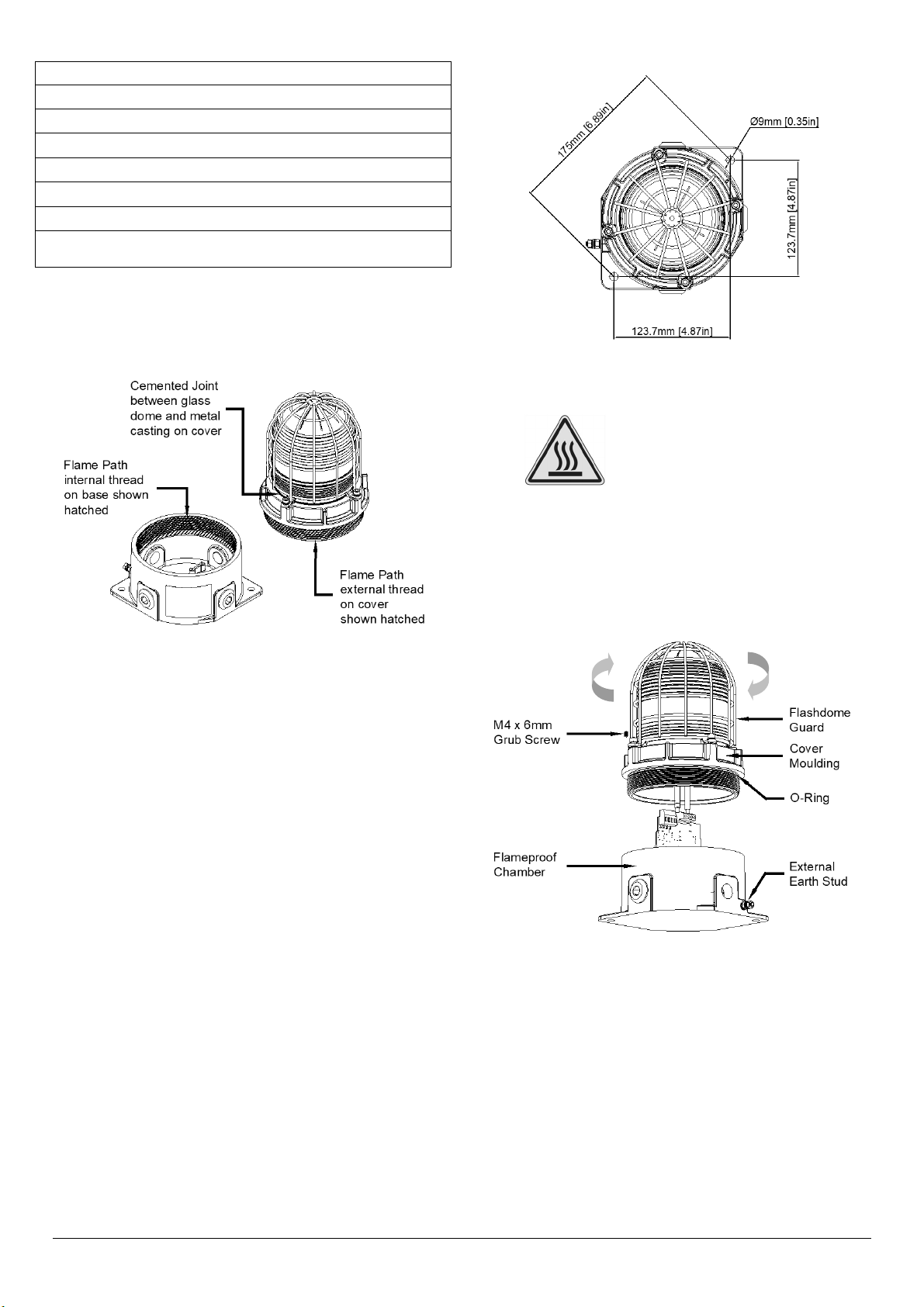
Figure 5: STExB2 Entries and Terminal Block Location.
When connecting wires to the terminals great care should be
taken to dress the wires so that when the cover is inserted into
the chamber the wires do not exert excess pressure on the
terminal blocks. This is particularly important when using
cables with large cross-sectional areas such as 2.5mm².
Earthing
Please note that for AC supply voltage product versions the
Earth terminal on the PCBA does not provide an earth
connection to the product enclosure. The enclosure must be
independently earthed using either the external or internal
earth fixing point, (see fig 9 and notes below).
Internal earthing connections should be made to the Internal
Earth terminal in the base of the housing using a ring crimp
terminal to secure the earth conductor under the earth clamp.
The earth conductor should be at least equal in size and rating
to the incoming power conductors.
External earthing connections should be made to the M5 earth
stud, using a ring crimp terminal to secure the earth conductor
to the earth stud. The external earth conductor should be at
least 4mm2 in size.

E2S Warning Signals Impress House, Mansell Road, Acton, London W3 7QH www.e2s.com Tel: +44 (0)208 743 8880
Document No. D199-00-201-IS Issue 5 28-11-22 Sheet 6 of 8
7.3. Cable Glands, Blanking Elements & Adapters
Follow the minimum temperature ratings of cables and cable
glands according to the approvals applied.
ATEX / IECEx & UKEx Requirements
For high ambient temperatures the cable entry
temperature may exceed 70ºC or the cable branching
point temperature may exceed 80ºC and therefore
suitable heat resisting cables and cable glands must be
used, with a rated service temperature at least as stated
below:
Table 2: ATEX / IECEx & UKEx Min. Ratings of Cables &
Cable Glands.
NEC / CEC Requirements Only
For high ambient temperatures the cable entry
temperature may exceed 60ºC or the cable branching
point temperature may exceed 60ºC and therefore
suitable heat resisting cables and cable glands must be
used, with a rated service temperature at least as stated
below:
Table 3: NEC / CEC Min. Ratings of Cables & Cable Glands.
Cable Glands & Blanking Plugs
Appropriate cable glands to be customer supplied.
ATEX / IECEx & UKEx Requirements Only
The cable entries have an M20 x 1.5 – 6H entry thread.
Only suitably rated and ATEX / IECEx & UKEx certified
cable glands must be used. They must be suitable for the
type of cable being used and also meet the requirements
of the current installation standards EN 60079-14 /
IEC60079-14.
If the installation is made using conduit, openings must
have a sealing fitting connected as close as practical to
the wall of the enclosure, but in no case more than the
size of the conduit or 50mm, whichever is the lesser.
Any unused cable entries must be closed with suitably
rated and ATEX / IECEx & UKEx certified blanking plugs.
NEC / CEC Requirements Only
The cable entries have an M20 x 1.5 – 6H entry thread.
If the installation is made using cable glands, only
suitably rated and certified cable glands must be used.
They must be suitable for the type of cable being used
and also meet the requirements of the current NEC /
CEC installation standards.
If the installation is made using conduit, openings must
have a sealing fitting connected as close as practical to
the wall of the enclosure, but in no case more than the
size of the conduit or 50mm, whichever is the lesser.
For use in Class I Division II locations, in order to
maintain the db type protection, flameproof conduit seals
and/or cable glands must be used.
Any unused cable entries must be closed with suitably
rated and certified blanking plugs.
Ingress Protection
Follow instructions according to the approvals applied.
ATEX / IECEx & UKEx Requirements Only
If a high IP (Ingress Protection) rating is required, then a
suitable sealing washer must be fitted under the cable
glands or blanking plugs. A minimum ingress protection
rating of IP6X must be maintained for installations in
explosive dust atmospheres.
For combustible dust applications, the cable entry device
and blanking elements shall be in type of explosion
protection and shall have an IP 6X rating.
NEC / CEC Requirements Only
If a high IP (Ingress Protection) rating is required then a
suitable sealing washer must be fitted under the cable
glands or blanking plugs. A minimum ingress protection
rating of IP6X must be maintained for installations in
explosive dust atmospheres.
Adapters
The STEx Beacon Range can be supplied with the following
types of adapters:
M20 to 1/2” NPT
M20 to 3/4” NPT
M20 to M25
It is important to note that stopping plugs cannot be fitted onto
adapters, only directly onto the M20 entries.
Any other adapters used must be suitably rated and certified
adapters.

E2S Warning Signals Impress House, Mansell Road, Acton, London W3 7QH www.e2s.com
Tel: +44 (0)208 743 8880
Document No. D199-00-201-IS
Issue 5
28-11-22 Sheet 7 of 8
8) Flash Pattern Settings
8.1. Flash Rate Setting
The STExB2 beacons can produce different flash patterns as
shown in Table 3. The flash patterns are selected by operation
of the flash setting DIP switch on the PCBA (See Fig 6).
Figure 6: DIP Switch Location.
Switch
Setting S1 Mode
00 1Hz (60FPM)
01 1.33Hz (80FPM)
10 1.5Hz (90FPM)
11 Double Flash
Table 4: Switch Positions for Flash Patterns
9) End of Line Monitoring (DC Units)
All DC units have a blocking diode fitted in their supply input
lines. An end of line monitoring diode or an end of line
monitoring resistor can be connected across the +ve and –ve
terminals in the flameproof chamber. If an end of line resistor
is used it must have a minimum resistance value of 3k3 ohms
and a minimum wattage of 0.5W or a minimum resistance
value of 500 ohms and a minimum wattage of 2W.
The resistor must be connected directly across the +ve and -
ve terminals as shown in the following drawing. The resistor
leads should be kept as short as possible.
Figure 7: End of Line Resistor Placement.
10) Interchangeable & Spare Parts
The beacon lens is interchangeable, contact European Safety
Systems Ltd for a replacement lens available in various
colours.
The guard is an integral part of the protection and must be
reassembled exactly the same way as it was disassembled.
To change the lens, unscrew the M5 socket head screws and
remove the M5 screws, M5 spring & flat washers.
Figure 8: Removal of Lens.
Remove the guard and replace the old lens with the new lens.
Warning – Hot surfaces. External surfaces
and internal components may be hot after
operation, take care when handling the
equipment.
Warning – high-intensity light source.
Avoid looking directly at the light source for
extended periods of time.

E2S Warning Signals Impress House, Mansell Road, Acton, London W3 7QH www.e2s.com Tel: +44 (0)208 743 8880
Document No. D199-00-201-IS Issue 5 28-11-22 Sheet 8 of 8
Figure 9: Changing of Lens.
Fit the guard back on to the lens and casting, align the holes
of the guard, lens and casting. To reattach the lens, the fixings
MUST be in the order shown in Figure 10.
Figure 10: Lens & Guard Fixings Order.
11) Maintenance, Overhaul and Repair
Maintenance, repair and overhaul of the equipment should
only be carried out by suitably qualified personnel in
accordance with the current relevant standards:
EN60079-19/IEC60079-19 Explosive atmospheres –
Equipment repair, overhaul and reclamation
EN 60079-17/IEC60079-17 Explosive atmospheres –
Electrical installations inspection and maintenance
Units must not be opened while an explosive atmosphere is
present.
If opening the unit during maintenance operations a clean
environment must be maintained and any dust layer removed
prior to opening the unit.
Repair of the flameproof threaded joints and cemented joints
is not permitted.
Potential electrostatic charging hazard - Clean only with a
damp cloth.
12) SIL 2 Reliability Data
Reliability and Functional safety IEC/EN61508 which has
been assessed and is considered suitable for use in low
demand safety function:
1. Random Hardware Failures and Architectural constraints
(route 2H).
2. As an unvoted item (i.e. hardware fault tolerance of 0) at
SIL 2.
The product was assessed against failure modes:
Failure respond to an input by lighting a beacon.
Spurious light output despite no input.
3. When employing the device in a SIL2 compliant system
the user should ensure frequent or continuous automatic
monitoring of continuity.
Integrity in respect of failure to function SIL2& SIL1
Total Failure rate 0.48 pmh
“Hazardous” failure rate (revealed) 0 pmh
“Hazardous” failure rate (unrevealed) 0.48 pmh
“Safe” failure rate (revealed) 0 pmh
“Safe” failure rate (unrevealed) 0
System type B
Hardware Fault Tolerance 0
Dia
g
nostic Covera
g
e >60%
PFD (hazardous failure) 2.1 x 10⁻³
Proof Test Interval Up to 1 year

Page left Intentionally blank

warning signals
2S
EUROPEAN SAFETY SYSTEMS LTD
IMPRESS HOUSE
MANSELL ROAD
ACTON
LONDON W3 7QH
WWW.E2S.COM
C
THIS DRAWING AND ANY INFORMATION OR DESCRIPTIVE
MATTER THEREIN IS COMMUNICATED IN CONFIDENCE AND
IS THE COPYRIGHT PROPERTY OF EUROPEAN SAFETY
SYSTEMS LTD. NEITHER THE WHOLE OR ANY EXTRACT MAY
BE DISCLOSED, LOANED, COPIED OR USED FOR
MANUFACTURING OR TENDERING PURPOSES WITHOUT THEIR
WRITTEN CONSENT.
EUROPEAN SAFETY SYSTEMS LTD.
AS PER LATEST DATE OF ISSUE SHOWN ABOVE
DRAWING TO BS8888:2000
GEOMETRIC TOLERANCES TO ISO1101:1983
LINEAR DIMENSIONAL TOLS
ANGULAR DIMENSIONAL TOLS
STANDARDS
MOD No. REASON - INITIAL - DATEISSUE
DATE
APPROVED
CHECKED DATE
DATE
DRAWN WEIGHT (Kg)
SURFACE FINISH
MATERIAL
ALTERNATIVE MATERIAL SHEETSCALE
TITLE
A3
IF IN DOUBT, ASK -
DO NOT SCALE
ALL DIMENSIONS IN MM
DRAWING NUMBER
A
B
C
D
E
F
G
109
G
F
E
78
6
5
D
C
134
2
A
B
D199-06-201
R.N.POTTS OF
STExB2 X05/X10/X15/X21
NTS 1 2
A
03/07/19
NEW PCBA & FORMAT INTRODUCED
J.S - 22/03/21
B
INTRODUCTION
RSR - 03/07/19
STExB2 BEACONS
R.N.POTTS 03/07/19
R.S.RAIT 03/07/19
BEACON WIRING DIAGRAMS
DC XENON STExB2 X05, X10, X15 & 21J UNITS
Line Monitoring
Power: +ve & -ve
OPTIONAL LINE MONITORING RESISTOR, CUSTOMER SUPPLIED,
RECOMMENDED MINIMUM VALUES:
R1
500Ω MIN, 2W MIN OR 3K3Ω MIN, 0.5W MIN
+ve IN
+ve OUT
-ve IN
-ve OUT
R1
+
+
-
-
INPUT TERMINALS & EOL RESISTOR ADDED
DAH - 17/12/19
C

warning signals
2S
EUROPEAN SAFETY SYSTEMS LTD
IMPRESS HOUSE
MANSELL ROAD
ACTON
LONDON W3 7QH
WWW.E2S.COM
C
THIS DRAWING AND ANY INFORMATION OR DESCRIPTIVE
MATTER THEREIN IS COMMUNICATED IN CONFIDENCE AND
IS THE COPYRIGHT PROPERTY OF EUROPEAN SAFETY
SYSTEMS LTD. NEITHER THE WHOLE OR ANY EXTRACT MAY
BE DISCLOSED, LOANED, COPIED OR USED FOR
MANUFACTURING OR TENDERING PURPOSES WITHOUT THEIR
WRITTEN CONSENT.
EUROPEAN SAFETY SYSTEMS LTD.
AS PER LATEST DATE OF ISSUE SHOWN ABOVE
DRAWING TO BS8888:2000
GEOMETRIC TOLERANCES TO ISO1101:1983
LINEAR DIMENSIONAL TOLS
ANGULAR DIMENSIONAL TOLS
STANDARDS
MOD No. REASON - INITIAL - DATEISSUE
DATE
APPROVED
CHECKED DATE
DATE
DRAWN WEIGHT (Kg)
SURFACE FINISH
MATERIAL
ALTERNATIVE MATERIAL SHEETSCALE
TITLE
A3
IF IN DOUBT, ASK -
DO NOT SCALE
ALL DIMENSIONS IN MM
DRAWING NUMBER
A
B
C
D
E
F
G
109
G
F
E
78
6
5
D
C
134
2
A
B
D199-06-201
R.N.POTTS OF
STExB2 X05/X10/X15/X21
NTS 2 2
03/07/19
STExB2 BEACONS
R.N.POTTS 03/07/19
R.S.RAIT 03/07/19
BEACON WIRING DIAGRAMS
AC XENON STExB2 X21 UNITS
Power: Live & Neutral
AC XENON STExB2 X05, X10 & X15 UNITS
Power: Live & Neutral
Neutral IN
Neutral OUT
Live IN
Live OUT
N
N
L
L
Neutral IN
Neutral OUT
Live IN
Live OUT
N
N
L
L
E
Earth
A
NEW PCBA & FORMAT INTRODUCED
J.S - 22/03/21
B
INTRODUCTION
RSR - 03/07/19
INPUT TERMINALS & EOL RESISTOR ADDED
DAH - 17/12/19
C

E2STelephone:+44(0)2087438880Fax:+44(0)2087404200Email:[email protected]www.e2s.comDC‐070_Issue_G(STEx).docx‐Page1of2‐QAF_252_Issue_5
EUDeclarationofConformity
Manufacturer: EuropeanSafetySystemsLtd.
ImpressHouse,MansellRoad,Acton
London,W37QH
UnitedKingdom
AuthorisedRepresentative:E2SWarnsignaltechnikUG
Charlottenstrasse45‐51
72764Reutlingen
Germany
EquipmentType: STExS1,STExS2,STExL1,STExL2
STExB2X05,STExB2X10,STExB2X15,STExB2X21
STExB2LD2,STExB2RT1
STExC1X05
STExJ2
Directive2014/34/EU:EquipmentandProtectiveSystemsforuseinPotentiallyExplosiveAtmospheres(ATEX)
NotifiedBodyforEUtypeExamination(ModuleB):ULInternationalDemkoA/S
NotifiedBodyNo.:0539
Borupvang5A,2750Ballerup,Denmark
EU‐typeExaminationCertificate(ModuleB):DEMKO16ATEX1466X
NotifiedBodyforQualityAssuranceNotification/ConformitytoEU‐type
basedon
qualityassuranceoftheproductionprocess(ModuleD):
SiraCertificationService
NotifiedBodyNo.:2813
CSAGroupNetherlandsB.V,Utrechtseweg310,6812AR,Arnhem,Netherlands
QualityAssuranceNotification(ModuleD):SIRA05ATEXM342
Provisionsfulfilledbytheequipment:II2GExdbIICT6…T3Gb
II2DExtbIIICT82°C…T137°CDb
IP6XDustProtectiontoEN60079‐0/EN60079‐31
Standardsapplied:ENIEC60079‐0:2018
EN60079‐1:2014
EN60079‐31:2014
Directive2014/30/EU:ElectromagneticCompatibilityDirective(EMC)
Standardsapplied:EN61000‐6‐1:2007
EN61000‐6‐2:2005
EN61000‐6‐3:2007/A1:2011/AC:2012
EN61000‐6‐4:2007/A1:2011
Directive2011/65/EU:Restrictionoftheuseofcertainhazardoussubstancesinelectricalandelectronicequipment(RoHS)
Theproductandallthecomponentscontainedwithinitareinaccordancewiththerestrictionoftheuseofhazardoussubstancesinelectricalandelectronic
equipment,includingamendmentbyDirective2015/863/EU.
Regulation(EC)1907/2006:Registration,Evaluation,AuthorisationandRestrictionofChemicals(REACH)
Theproductandallthecomponentscontainedwithinitarefreefromsubstancesofveryhighconcern.
OtherStandardsandRegulations
EN60529:1991/A1:2000/A2:2013‐Degreesofprotectionprovidedbyenclosures(IPcode)–enclosureratedIP66

E2STelephone:+44(0)2087438880Fax:+44(0)2087404200Email:[email protected]www.e2s.comDC‐070_Issue_G(STEx).docx‐Page2of2‐QAF_252_Issue_5
MartinStreetzDocumentNo.:DC‐070_Issue_G
QualityAssuranceManagerDateandPlaceofIssue:London,03/12/2021
EUDeclarationofConformity
OnbehalfofEuropeanSafetySystemsLtd.,Ideclarethat,onthedatetheequipmentaccompaniedbythisdeclarationisplacedonthemarket,theequipment
conformswithalltechnicalandregulatoryrequirementsoftheabovelisteddirectives,regulationsandstandards.
ThisDeclarationisissuedunderthesoleresponsibilityofthemanufacturer.

E2STelephone:+44(0)2087438880Fax:+44(0)2087404200Email:[email protected]www.e2s.comDC‐100_Issue_A(STEx)‐Page1of2‐QAF_252_Issue_5
UKCADeclarationofConformity
Manufacturer: EuropeanSafetySystemsLtd.
ImpressHouse,MansellRoad,Acton
London,W37QH
UnitedKingdom
EquipmentType: STExS1,STExS2,STExL1,STExL2
STExB2X05,STExB2X10,STExB2X15,STExB2X21
STExB2LD2,STExB2RT1
STExC1X05
STExJ2
DirectiveUKSI2016:1107(asamendedbyUKSI2019:696)–Schedule3A,Part1:ProductorProtectiveSystemIntendedforuseinPotentiallyExplosiveAtmospheres
(UKCA)
NotifiedBodyforUKtypeExamination(ModuleB):ULInternational(UK)Ltd
NotifiedBodyNo.:0843
Unit1‐3HorizonKingslandBusinessPark,WadeRoad,
Basingstoke,HampshireRG248AHUK
UK‐typeExaminationCertificate(ModuleB):UL21UKEX2019X
NotifiedBodyforQualityAssuranceNotification/ConformitytoEU‐type
basedon
qualityassuranceoftheproductionprocess(ModuleD):
SiraCertificationService
NotifiedBodyNo.:0518
RakeLane,Eccleston,ChesterCH49JN,UK
QualityAssuranceNotification(ModuleD):CSAE22UKQAN0046
Provisionsfulfilledbytheequipment:II2GExdbIICT6…T3Gb
II2DExtbIIICT85°C…T137°CDb
IP6XDustProtectiontoEN60079‐0/EN60079‐31
Standardsapplied:ENIEC60079‐0:2018
EN60079‐1:2014
EN60079‐31:2014
Directive2014/30/EU:ElectromagneticCompatibilityDirective(EMC)
Standardsapplied:EN61000‐6‐1:2007
EN61000‐6‐2:2005
EN61000‐6‐3:2007/A1:2011/AC:2012
EN61000‐6‐4:2007/A1:2011
Directive2011/65/EU:Restrictionoftheuseofcertainhazardoussubstancesinelectricalandelectronicequipment(RoHS)
Theproductandallthecomponentscontainedwithinitareinaccordancewiththerestrictionoftheuseofhazardoussubstancesinelectricalandelectronic
equipment,includingamendmentbyDirective2015/863/EU.
Regulation(EC)1907/2006:Registration,Evaluation,AuthorisationandRestrictionofChemicals(REACH)
Theproductandallthecomponentscontainedwithinitarefreefromsubstancesofveryhighconcern.
OtherStandardsandRegulations
EN60529:1991/A1:2000/A2:2013‐Degreesofprotectionprovidedbyenclosures(IPcode)–enclosureratedIP66

E2STelephone:+44(0)2087438880Fax:+44(0)2087404200Email:[email protected]www.e2s.comDC‐100_Issue_A(STEx)‐Page2of2‐QAF_252_Issue_5
MartinStreetzDocumentNo.:DC‐100_Issue_A
QualityAssuranceManagerDateandPlaceofIssue:London,24/02/2022
UKCADeclarationofConformity
OnbehalfofEuropeanSafetySystemsLtd.,Ideclarethat,onthedatetheequipmentaccompaniedbythisdeclarationisplacedonthemarket,theequipment
conformswithalltechnicalandregulatoryrequirementsoftheabovelisteddirectives,regulationsandstandards.
ThisDeclarationisissuedunderthesoleresponsibilityofthemanufacturer.

Page left Intentionally blank
This manual suits for next models
20
Table of contents
Other E2S Lighting Equipment manuals
Popular Lighting Equipment manuals by other brands

Sunco
Sunco MOTION SHOP LIGHT Install Guide and Manual

Claypaky
Claypaky IGLOO instruction manual

superbrightleds
superbrightleds HBU-50K240W user manual

Lightmybricks
Lightmybricks Light Kit for LEGO Star Wars The Razor Crest... installation guide

COLORKINETICS
COLORKINETICS ColorBlast 12 Powercore user guide

HAMPTON BAY
HAMPTON BAY ORON HDP12070BN Use and care guide