E2S WP7-PB-S User manual

_______________________________________________________________________________________________________________________________
European Safety Systems Ltd. Impress House, Mansell Road, Acton, London W3 7QH www.e2s.com Tel: +44 (0)208 743 8880
Document No. D234-00-201-IS_Issue_2 10-11-2022 Sheet 1 of 4
INSTRUCTION MANUAL (WEATHER PROOF)
WP7 PB/PM/PT CALL POINTS
1) Certification & Ratings
All units have a rating label, which carries the following
important information: -
Model No.: WP7-PB-S (Single Switch)
WP7-PB-D (Dual Switch)
WP7-PM-S (Single Switch)
WP7-PM-D (Dual Switch)
WP7-PT-S (Single Switch)
WP7-PT-D (Dual Switch)
UKCA Marking
IP Rating: IP66/67 to EN/IEC60529
Ambient Temperature Range: -55°C to +75°C
2) Location and Mounting
The location of the call point should enable ease of access
for operation and testing. The unit should be mounted using
the 4 off fixing holes which will accept up to M5 sized fixings.
They should only be fixed to services that can carry the
weight of the unit.
To gain access to the mounting holes in the base the front
cover must be removed. See Section 3.
80,0 [3,15in.]
114,0 [4,49in.]
134,0 [5,28in.]
137,0 [5,39in.]
133,9 [5,27in.]
Ø6,4 [Ø0,25in.]
Fig. 1 View of base unit showing fixing centres (in mm).
3) Access to the Enclosure
To access the chamber, remove the four off M6 x 50
stainless steel cap head cover bolts
Once the screws are removed the cover will hang down out
of the way to gain access to the terminals, the internal earth
terminal and mounting hole recesses.
Fig. 2 Accessing the Explosion proof Enclosure.
Check that the earth bonding wire between the two castings
is secure and the ‘O’ ring seal is in place.
4) Earthing
The units are provided with internal and external earth
terminals which are mounted in the base of the unit.
Internal earthing connections should be made to the Internal
Earth terminal in the base of the housing using a ring crimp
terminal to secure the earth conductor under the earth clamp.
The earth conductor should be at least equal in size and
rating to the incoming power conductors.
When using the internal earth terminal ensure that the
stainless steel M4 flat washer is between the incoming earth
wire and the enclosure.
Warning – High voltage may be present,
risk of electric shock. DO NOT open
when energised, disconnect power
before opening.
CE Marking
Call Point Cover
Call Point Base
M6x
5
0 Cap head Cover Bolts
-
4 off Po
sition
s

_______________________________________________________________________________________________________________________________
European Safety Systems Ltd. Impress House, Mansell Road, Acton, London W3 7QH www.e2s.com Tel: +44 (0)208 743 8880
Document No. D234-00-201-IS_Issue_1 10-11-2022 Sheet 2 of 4
M/S 1 M/S 2
+ - + -
1 3 4 6
SERIES 1 SERIES 2
EOL 1 EOL 2
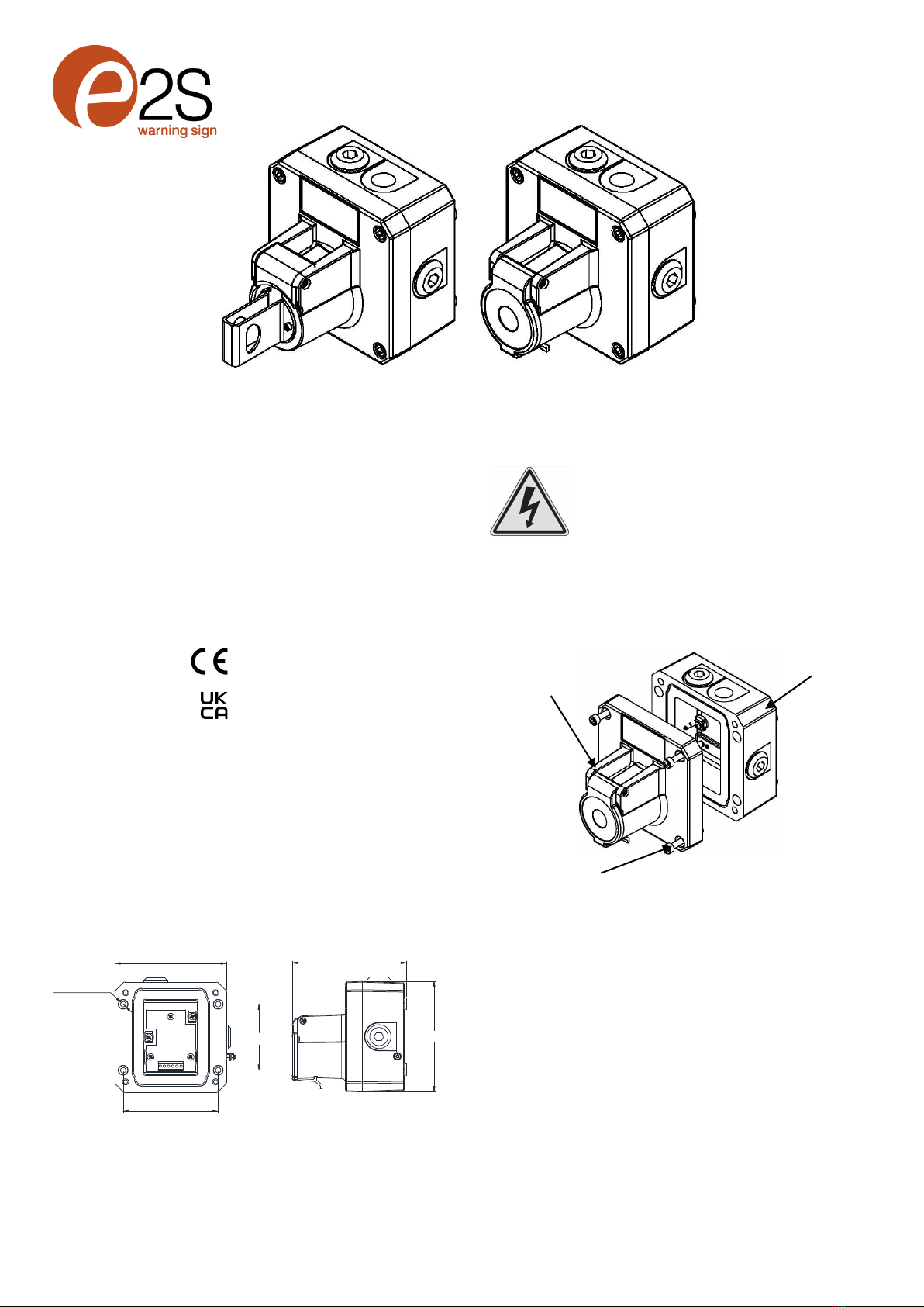
Fig 3 Earth terminals
5) Power Supply Selection
Electrical Ratings
Input Voltage:
AC voltage 250V Max Current 5.0A Max
DC voltage 75V Max Current 0.75A Max
DC voltage 50V Max Current 1.0A Max
DC voltage 30V Max Current 5.0A Max Resistive Load;
Inductive Load 3.0A Max
DC voltage 12V Max Current 5.0A Max
Electrical connections are to be made into the terminal blocks
/ DIN rail provided. See Section 8 for wiring options.
6) Selection of Cable. Cable Glands, Blanking
Elements & Adapters
The cable gland entries have an M20 x 1.5 entry thread.
The WP7 Call Point range can be supplied with the following
types of adapters:
M20 to ½” NPT
M20 to ¾” NPT
M20 to M25
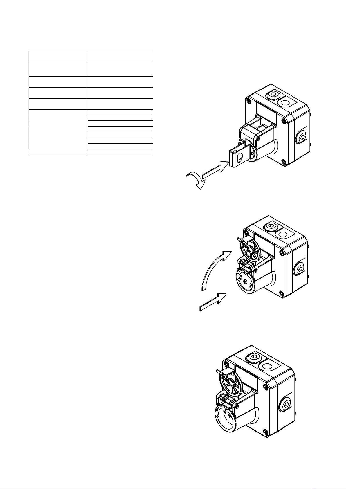
7) Cable Connections
Electrical Connections are to be made into the terminal
blocks using solid or stranded wire. See section 3 of this
manual for access to the enclosure.
Wires having a cross sectional area between 0.5 mm² to
2.5mm² (AWG 20 – 14) can be connected to each terminal
way.
If an input and output wire is required the 2-off Live/Neutral or
+/- terminals can be used. If fitting 2-off wires to one terminal
way the sum of the 2-off wires must be a maximum cross
sectional area of 2.5mm².
Strip wires to 8mm. Wires may also be fitted using ferrules.
Terminal screws need to be tightened down with a tightening
torque of 0.45 Nm / 5 Lb-in.
When connecting wires to the terminals great care should be
taken to dress the wires so that when the cover is inserted
into the chamber the wires do not exert excess pressure on
the terminal blocks. This is particularly important when using
cables with large cross sectional areas such as 2.5mm².
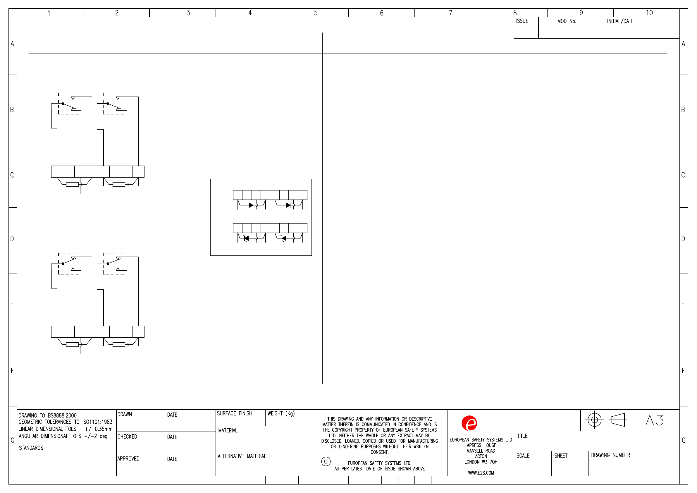
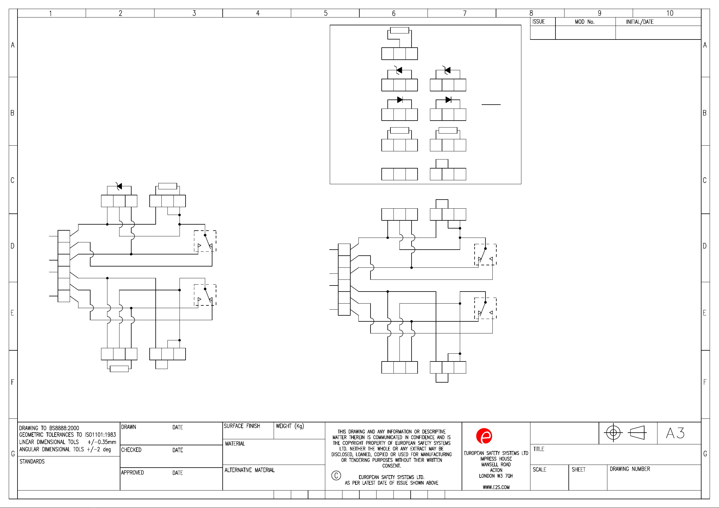
8) Wiring Unit
The units come with two options for the terminal block.
A DIN rail version which has 8-way connection and allows for
full configuration at factory or limited wiring of EOL devices by
customer.
The PCB Terminal Version has a 6-way connector but is
designed to allow for full configuration with Series and EOL
devices in a number of wiring configurations.
For EOL and Series device limitations and configurations see
Section 9.
For full wiring details see wiring schematic D234-06-001.
Wiring Connections for 8-Way DIN Rail
Fig. 4 DIN Rail in Base
Wiring Connections For 6-Way PCB Terminal Board
Fig. 5 PCB Terminal Block in Base
See section 9 and pages 5, 6 & 7 for details of adding Series
and EOL devices on the PCB. This can either be done at the
order stage or added to the correct terminal blocks afterward.
9) End-of-Line and Series Devices
All models can be fitted with series resistors, end-of-line
monitoring resistors, monitoring diodes, zener diodes and
also specific customer modules if supplied with direct current
up to 50Vdc.
Wiring terminal
Internal Earthing
External Earthing

_______________________________________________________________________________________________________________________________
European Safety Systems Ltd. Impress House, Mansell Road, Acton, London W3 7QH www.e2s.com Tel: +44 (0)208 743 8880
Document No. D234-00-201-IS_Issue_1 10-11-2022 Sheet 3 of 4
Series (In line) device;
resistor – SxxxR
diode – SD1
zener – SxxxZ
LED
The following table 1 shows limitations for all possible
variations:
Suggested EOL/ Series
Device Type
Type of component
fitted
Value
End-of-Line Resistor 330Ω
Suggested Min.
End-of-Line Diode
Type 1N5401
2W
Series Resistor 330Ω
Suggested
Min.
Series Zener Diode
Type 1N5333B
Suggested Sizes
3.3V
4.7V
5.1V
5.6V
6.2V
6.8V
10V
12V
EOL (End of line) device;
resistor – ExxxR
diode – ED1
zener – ExxxZ
Microswitch 1 = M/S 1
Microswitch 2 = M/S 2
The unit can be wired with a maximum of 4 module devices.
Please refer to wiring schematic D234-06-001
When customer is fitting EOL or Series device ensure device
leads are insulated or routed so not to create an electrical
short.
10) Testing unit operation
The push button types -PB -PT and -PM are all operated by
pressing in the main plunger down activating the switch.
The -PB plunger needs to be firstly twisted by 90 degrees
clockwise to position shown and then pressed in.
Fig 6 -PB Version Twist and Push Action
The -PM and -PT need to have the protective flip lid opened
first and then the main plunger pressed in.
Fig 7 -PT & -PM Versions Push Action
On –PM versions the operation is momentary and as such
the plunger will reset automatically once the pressure on the
plunger is released.

_______________________________________________________________________________________________________________________________
European Safety Systems Ltd. Impress House, Mansell Road, Acton, London W3 7QH www.e2s.com Tel: +44 (0)208 743 8880
Document No. D234-00-201-IS_Issue_1 10-11-2022 Sheet 4 of 4
On -PB the plunger will remain in the down position until the
unit is reset. This is done by pulling the plunger back up to
the start position shown in fig 6. Then the plunger is twisted
back 90 degrees anti-clockwise to the stop.
On -PT the plunger will remain in the down position until the
unit is reset. This is done by lifting the plunger back up using
the tool reset key provided.

ALL DIMENSIONS IN MM
IF IN DOUBT, ASK -
DO NOT SCALE
2S
warning signals
NTS
WP7 CALL POINT
WIRING / CIRCUIT OPERATION DIAGRAM
D234-06-201
13
OF
1
WP7
Introduction
JS 11-02-2020
R.N.POTTS
J. SPILLER 11-02-2020
11-02-2020
11-02-2020
R.N.POTTS
1 2 3 4 56
M/S 1
78
KEY:
COM - Common
N/C - Normally Closed
(Contacts closed in unoperated state)
N/O - Normally Open
(Contacts open in unoperated state)
1 2 3 4 56
M/S 1
78
COM N/O
WIRE LINK
1A - Circuit as shown in Unoperated condition
Terminals (4/5) & (7/8) open
Terminals (4/5) & (6) closed
R B
YR
DIODE
ZENER DIODE
POSITIVE (+) COMMON
(IF DIODES SUPPLIED & CONFIGURED BY E2S)
1 2 3 4 5678
EOL
SER
M/S 1
Standard Unit withsuggested Series / EOL
Devices - Alternative Configuration
R
2A - Circuit as shown in Unoperated condition
Terminals (4/5) & (7/8) open
Terminals (4/5) & (6) closed
Standard Unit as supplied by E2S
Without Series / EOL Devices
N/C COM N/O
N/C
EOL
SER
1 2 3 4 56
M/S 1
78
COM N/O
WIRE LINK
1B - Circuit as shown in Unoperated condition
Terminals (4/5) & (7/8) closed
Terminals (4/5) & (6) open
R
N/C
1 2 3 4 5678
1 2 3 4 5678
COM N/O
N/C
COM
+
N/O
-
N/C
-
COM
+
N/O
-
N/C
-
Standard Unit showing positions of
optional Series / EOL Devices
1 2 3 4 56
M/S 1
78
R
2B - Circuit as shown in Unoperated condition
Terminals (4/5) & (7/8) closed
Terminals (4/5) & (6) open
COM N/O
N/C
EOL
SER
NOTE: These can be fitted either
by customer or pre-installed by
E2S at point of order.
When fitting diodes or zener diodes, polarity
across devices must be observed
(Resistor polarity is unimportant)
SERIES
EOL
Wiring option shown with EOL &
series devices acting in parallel
3A - Circuit as shown in Unoperated condition
Terminals (4/5) & (7/8) open
Terminals (4/5) & (6) closed
DIODE
ZENER DIODE
POSITIVE (+) COMMON
(IF DIODES SUPPLIED & CONFIGURED BY E2S)
1 2 3 4 5678
1 2 3 4 5678
COM
+
N/O
-
N/C
-
COM
+
N/O
-
N/C
-
When fitting diodes or zener diodes, polarity
across devices must be observed
(Resistor polarity is unimportant)
SERIES
EOL
Wiring option shown with EOL &
series devices acting in series
4 5 7 8
4 5 7 8
1 2 3 4 5678
EOL
SER
M/S 1
R
COM N/O
N/C
3B - Circuit as shown in Operated condition
Terminals (4/5) & (7/8) closed
Terminals (4/5) & (6) open
E2S PART NO.
WP7-PB
WP7-PM
WP7-PT
DESCRIPTION
WP7 WEATHERPROOF CALL POINT PUSH BUTTON
WP7 WEATHERPROOF CALL POINT MOMENTARY PUSH BUTTON
WP7 WEATHERPROOF CALL POINT PUSH BUTTON TOOL RESET
DATA REFERENCE
1.41.030
1.41.040
1.41.050
WP7 [ ] [S] [D] SWITCH TYPE: [S] - Single Microswitch TERMINAL TYPE [D] - DIN RAIL
B
Y
B
YB
YB
Y
B
Y

ALL DIMENSIONS IN MM
IF IN DOUBT, ASK -
DO NOT SCALE
2S
warning signals
NTS
WP7 CALL POINT
WIRING / CIRCUIT OPERATION DIAGRAM
D234-06-201
23
OF
1Introduction
JS 11-02-2020
WP7 R.N.POTTS
J. SPILLER 11-02-2020
11-02-2020
11-02-2020
R.N.POTTS
1 2 3 4 56
M/S 1 M/S 2
78
N/O
COM EOL
R R
4A - Circuit as shown in Unoperated condition
Terminals (1) & (4) M/S 1 and (5) & (8) M/S 2 open
Terminals (1) & (3) M/S 1 and (5) & (7) M/S 2 closed
WP7 [ ] [D] [D] SWITCH TYPE: [D] - Double Microswitch TERMINAL TYPE [D] - DIN RAIL
DIODE
ZENER DIODE
POSITIVE (+) COMMON
(IF DIODES SUPPLIED & CONFIGURED BY E2S)
1 2 3 4 5678
1 2 3 4 5678
COM
+
N/O
-
N/C
-
When fitting diodes or zener diodes, polarity
across devices must be observed
(Resistor polarity is unimportant)
Standard Unit showing possitions
of optional Series / EOL Devices
NOTE: These can be fitted either
by customer or pre-installed by
E2S at point of order.
N/C
N/O
COM EOL
N/C
1 2 3 4 56
M/S 1 M/S 2
78
N/O
COM EOL
R R
4B - Circuit as shown in Operated condition
Terminals (1) & (4) M/S 1 and (5) & (8) M/S 2 closed
Terminals (1) & (3) M/S 1 and (5) & (7) M/S 2 open
N/C
N/O
COM EOL
N/C
WP7 [ ] [X] [D] SWITCH TYPE: [X] - SPECIAL ORDER TERMINAL TYPE [D] - DIN RAIL
Other wiring configurations are available pre-configured
(e.g. Dual switch configured with series and EOL devices)
Contact E2S sales for special wiring request
COM
+
N/O
-
N/C
-
COM
+
N/O
-
N/C
-
COM
+
N/O
-
N/C
-
B
YB
Y
B
YB
Y

ALL DIMENSIONS IN MM
IF IN DOUBT, ASK -
DO NOT SCALE
2S
warning signals
NTS
WP7 CALL POINT
WIRING / CIRCUIT OPERATION DIAGRAM
D234-06-201
33
OF
1Introduction
JS 11-02-2020
1 2 3
NO SERIES DEVICE
DEFAULT PIN 1 & 2
LINKED
1 2 3
SR1 OR SR2
SERIES RESISTOR
FIT IN 1 & 3
1 2 3
SD1 OR SD2
SERIES DIODE
FIT IN 1 & 3
1 2 3
SZ1 OR SZ2
SERIES ZENER
DIODE FIT IN 1 & 3
1 2 3
NO EOL DEVICE
DEFAULT NOT
LINKED
1 2 3
ER1
EOL RESISTOR
FIT IN 1 & 3
1 2 3
ED1
EOL DIODE
FIT IN 1 & 3
1 2 3
EZ1
EOL ZENER
DIODE FIT IN 1 & 3
1 2 3
ER1
EOL RESISTOR
FIT IN 2 & 3
WIRING OPTION 2
1 2 3 4 56
- -
M/S 1 M/S 2
1 2 3 1 2 3
SERIES
DEVICE 1 RESISTOR
EOL
DEVICE 1 EZ1
1 2 3 1 2 3
5A - Circuit as shown in Unoperated condition
Terminals +(1) & -(3) M/S 1 and +(4) & -(6) M/S 2 open
Terminals +(1) & (2) M/S 1 and +(4) & (5) M/S 2 closed
M/S 1
+M/S 2
+
SERIES
DEVICE 2 NONE
(DEFAULT LINK)
EOL
DEVICE 2 RESISTOR
1 2 3 4 56
- -
M/S 1 M/S 2
1 2 3 1 2 3
SERIES
DEVICE 1
EOL
DEVICE 1
1 2 3 1 2 3
M/S 1
+M/S 2
+
SERIES
DEVICE 2
EOL
DEVICE 2
RB
YR
RR
5B - Circuit as shown in Operated condition
Terminals +(1) & (2) M/S 1 and +(4) & (5) M/S 2 open
Terminals +(1) & -(3) M/S 1 and +(4) & -(6) M/S 2 closed
WP7 R.N.POTTS
J. SPILLER 11-02-2020
11-02-2020
11-02-2020
R.N.POTTS
Optional Single or Double Microswitch
Circuit shown with Double Microswitch, Unit un-operated : WP7 PCB Version
WP7 [ ] [S] [P] SWITCH TYPE: [S] - Single Microswitch TERMINAL TYPE [P] - PCB
WP7 [ ] [D] [P] SWITCH TYPE: [D] - Double Microswitch TERMINAL TYPE [P] - PCB
B
Y
B
YB
Y

E2S Telephone: +44 (0)20 8743 8880 Fax: +44 (0)20 8740 4200 Email: sal[email protected] www.e2s.com DC-081_Issue_C Page 1 of 1 QAF_252_Issue_5
Martin Streetz Document No.: DC-081_Issue_C
Quality Assurance Manager Date and Place of Issue: London, 23/11/2022
EU & UKCA Declaration of Conformity
Manufacturer: European Safety Systems Ltd.
Impress House, Mansell Road, Acton
London, W3 7QH
United Kingdom
Authorised Representative: E2S Warnsignaltechnik UG
Charlottenstrasse 45-51
72764 Reutlingen
Germany
Equipment Type: WP3-BG,
WP6-PB,
WP7-PB, WP7-PT, WP7-PM
Directive 2014/30/EU: Electromagnetic Compatibility Directive (EMC)
Standards applied:
EN 61000
-
6
-
1:2007
EN 61000-6-2:2005
EN 61000-6-3:2007 / A1:2011 / AC: 2012
EN 61000-6-4:2007 / A1:2011
Directive 2006/95/EC (until 19th April 2016) / Directive 2014/35/EU (from 20th April 2016): Low Voltage Directive (LVD)
Standards applied:
EN
60947
-
1:2007+A2:2014
Directive 2011/65/EU: Restriction of the use of certain hazardous substances in electrical and electronic equipment (RoHS)
The product and all the components contained within it are in accordance with the restriction of the use of hazardous substances in electrical and electronic
equipment, including amendment by Directive 2015/863/EU.
Regulation (EC) 1907/2006: Registration, Evaluation, Authorisation and Restriction of Chemicals (REACH)
The product and all the components contained within it are free from substances of very high concern.
Other Standards and Regulations
EN 60529:1992+A2:2013 - Degrees of protection provided by enclosures (IP code) – enclosure rated IP66
On behalf of European Safety Systems Ltd., I declare that, on the date the equipment accompanied by this declaration is placed on the market, the equipment
conforms with all technical and regulatory requirements of the above listed directives, regulations and standards.
This Declaration is issued under the sole responsibility of the manufacturer.
This manual suits for next models
5
Table of contents
Other E2S Safety Equipment manuals