E2S IS-CP4B-BG User manual

European Safety Systems Ltd. Impress House, Mansell Road, Acton, London W3 7QH sa[email protected] Tel: +44 (0)208 743 8880
Document D150-00-551-IS Issue 4 11-08-2022 Sheet 1 of 2 www.e2s.com Fax +44 (0)208 740 4200
INSTRUCTION MANUAL
IS-CP4B-BG Break Glass Manual Call Point
For use in Flammable Gas Atm
osphe
res
IS-CP4B-BG
Manual Call Point – Break Glass
With Resistor Modules
For use in Flammable Gas and
Combustible Dust Atmospheres.
1) Introduction
The IS-CP4B-BG is a breakglass manual call point
which is certified intrinsically safe to the European
and International Gas standards. The unit meets
the requirements of the ATEX directive 2014/34/EU
and IECEx scheme.
The call point can be used in hazardous areas
where potentially flammable gas atmospheres may
be present.
The IS-CP4B-BG has up to two monitoring
resistors. The units are Group II, EPL (equipment
protection level) Ga. The equipment is certified ‘Ex
ia IIC T4 Ga’ and as such may be used in Zones 0,
1 and 2 with flammable gases and vapours with
gas groups IIA, IIB & IIC and temperature classes
T1, T2, T3 and T4.
The equipment needs to be installed with ATEX
and/or IECEx certified Zener Barriers or Galvanic
Isolators.
2) Marking
All units have a rating label, which carries the
following important information:-
Unit Type No.:
IS-CP4B-BG Manual Call Point
Code:
Ex ia IIC T4 Ga
IP66
Ui=30V Ii=500mA Pi=1.1W Ci=0 Li=0
–40ºC <= Ta <= +50ºC
Certificate No.:
SIRA 09ATEX2287X
IECEx SIR 09.0122X
CSAE 21UKEX2555X
Epsilon x: II 1G2D
CE Marking
Notified 2813
Body No.
UKCA Marking
Notified Body No. 0518
Year/Serial No. i.e. 10/1CP4BBG000001
WARNING - DO NOT OPEN WHEN AN
EXPLOSIVE ATMOSPHERE MAY BE PRESENT
3) Type Approval Standards
The beacon has an EC Type examination
certificate issued by SIRA and have been approved
to the following standards:-
EN IEC 60079-0:2018 / IEC 60079-0:2017
EN 60079-11:2012 / IEC 60079-11:2011
IEC 60079-26:2014
The equipment is certified for use in ambient
temperatures in the range -40oC to +50oC and shall
not be used outside this range.
4) Installation Requirements
Installation of this equipment shall only be carried
out by suitably trained personnel in accordance
with the applicable code of practice e.g.
IEC 60079-14/EN 60079-14.
Repair of this equipment shall only be carried out
by the manufacturer or in accordance with the
applicable code of practice e.g. IEC 60079-19/EN
60079-19.
The certification of this equipment relies on the
following materials used in its construction:
Enclosure: Aluminium Pressure Die Cast Body
LM6
Through enclosure mechanism: Plastic Nylon Zytel
Injection Moulded
Sealing of enclosure and mechanism: O-ring
Acrylonitrile-Butadiene Rubber
If the equipment is likely to come into contact with
aggressive substances, then it is the responsibility
of the user to take suitable precautions that prevent
it from being adversely affected, thus ensuring that
the type of protection is not compromised.
“Aggressive substances” - e.g. acidic liquids or
gases that may attack metals, or solvents that may
affect polymeric materials.
“Suitable precautions” - e.g. regular checks as part
of routine inspections or establishing from the
material’s data sheet that it is resistant to specific
chemicals.
Refer to certificates SIRA 09ATEX2287X and
IECEx SIR 09.0122X for special conditions of safe
use.
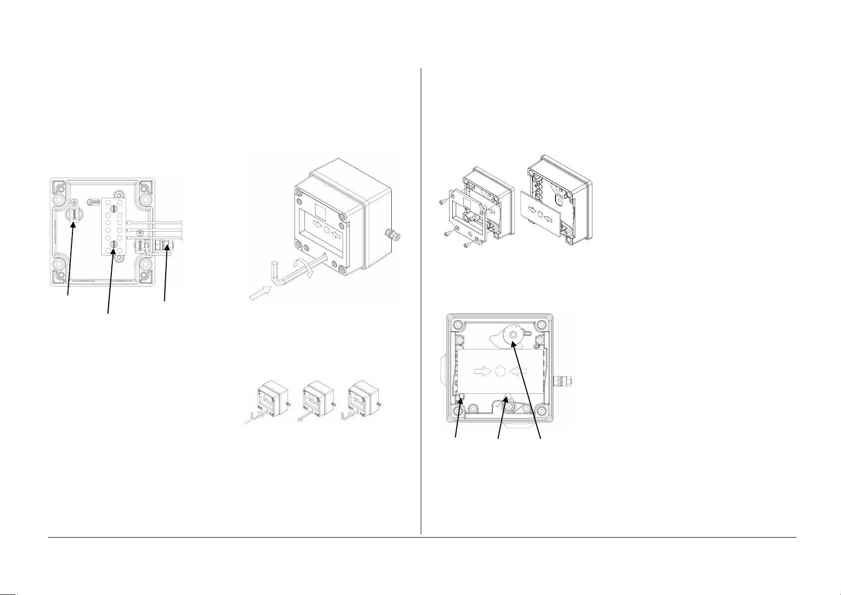
5) Call Point Location and Mounting
The location of the call point should enable ease of
access for operation and testing. The unit should
be mounted using the 4 off fixing holes which will
accept up to M4 sized fixings.
When installing in Zone 0 applications, ensure that
the equipment enclosure is protected from impact.
View of base unit showing fixing centres.
To gain access to the mounting holes in the base
the front cover must be removed.
This is achieved by removing the 4 off M4 cap
head bolts holding on the cover.
Once the screws are removed the cover will hang
down out of the way to gain access to the Ex e
terminal block, the internal earth terminal and
mounting hole recesses.

European Safety Systems Ltd. Impress House, Mansell Road, Acton, London W3 7QH sa[email protected] Tel: +44 (0)208 743 8880
Document D150-00-551-IS Issue 4 11-08-2022 Sheet 2 of 2 www.e2s.com Fax +44 (0)208 740 4200
6) Earthing
The unit has both internal and external earth
terminals.
It is recommended that a cable crimp lug is used
on the earth wires.
The internal earth wire is placed under a earth
clamp which will stop the cable twisting. This is
secured by an M4 screw and spring washer.
The external earth lug should be located between
the two M5 washers provided and securely locked
down with the M5 spring washer and two locknuts.
Internal Earth
terminal External
Earth Stud
Ex e terminal block
7) Cable connections
There are 3 off cable entries for M20x1.5 cable
glands or stopping plugs.
Cable glands or stopping plugs must be rated IP66.
The unit can be wired in a number of different ways
depending on the resistor combination selected.
Option 1 – EOL (End of line) Resistor
Option 2 – Series (In line) resistor
Option 3 – Series and EOL resistors
The equipment needs to be installed with ATEX
and/or IECEx certified Zener Barriers or Galvanic
Isolators.
For wiring schematic refer to drawing D150-06-051
8) Testing unit operation
The breakglass unit can be tested without the need
to break/replace the frangible glass element.
A test key (7mm Allen key) is used to mechanically
drop the glass down activating the switch.
The test key is inserted in the test cam and rotated
clockwise by an angle of 60º the glass element will
visibly drop down in the viewable window.
The call point switch will now changeover it’s
contacts to operate the alarm.
Once testing is complete the unit needs to be
reset, the test key is rotated back anticlockwise by
an angle of 60º back to its original position. The
glass element should now raise up so it is level
again in the viewable window.
1. 2. 3.
Insert test Hold in Rotate back
Key rotate position anticlockwise
clockwise during to reset
60º test
9) Replacement of glass element
If the breakglass unit has been operated the
broken glass element can be quickly replaced.
The breakglass cover plate is removed by
unscrewing the 4 off M4 cap head screws attaching
it.
Once cover is removed the broken glass will be
free to be removed, clean out any other fragments
of glass carefully.
To fit the new glass element rotate the top cam
clockwise by an angle of 50º (use a 6mm Allen
key) this will than allow the glass to fit back into the
pocket it sits in, resting on the pivot point and test
cam, release the top cam to rest on the top of the
glass element.
Pivot point Test Cam Top Cam (rotate)
Replace the cover plate and tighten the 4 off M4
cap head screws.
Ensure the glass element is free to move under the
cover plate. This can be done by running through
the units test operation. See section 8 of this
instruction manual.

BExCP3B/C/D/E CALL POINTS
R.N.POTTS
2S
ADDED. D.A.H - 26-08-2020
INTRODUCTION
1
07-02-20
07-02-20
WWW.E2S.COM
C
LONDON W3 7QH
ACTON
MANSELL ROAD
IMPRESS HOUSE
EUROPEAN SAFETY SYSTEMS LTD
11NTS
AS PER LATEST DATE OF ISSUE SHOWN ABOVE
EUROPEAN SAFETY SYSTEMS LTD.
WRITTEN CONSENT.
MANUFACTURING OR TENDERING PURPOSES WITHOUT THEIR
ANGULAR DIMENSIONAL TOLS
STANDARDS
MOD No. REASON - INITIAL - DATEISSUE
DATE
APPROVED
CHECKED DATE
DATE
DRAWN WEIGHT (Kg)
SURFACE FINISH
MATERIAL
ALTERNATIVE MATERIAL SHEETSCALE
TITLE
A3
LINEAR DIMENSIONAL TOLS
DO NOT SCALE
ALL DIMENSIONS IN MM
DRAWING NUMBER
A
B
C
D
E
F
G
109
G
F
E
78
6
5
D
C
134
2
A
B
D150-06-051
2
D.HOWGILL
R.N.POTTS
07-02-20
OF
IF IN DOUBT, ASK -
CALL POINT WIRING SCHEMATIC
BExCP3B/C/D/E-BG/PB/PT MANUAL
D.A.H - 07-02-2020
THIS DRAWING AND ANY INFORMATION OR DESCRIPTIVE
MATTER THEREIN IS COMMUNICATED IN CONFIDENCE AND
IS THE COPYRIGHT PROPERTY OF EUROPEAN SAFETY
SYSTEMS LTD. NEITHER THE WHOLE OR ANY EXTRACT MAY
BE DISCLOSED, LOANED, COPIED OR USED FOR
DRAWING TO BS8888:2000
GEOMETRIC TOLERANCES TO ISO1101:1983
TYPE E ADDED ; SIMPLIFIED DIAGRAMS
ACN0077
warning signals
DATA REFERENCE
1.24.070
1.24.080
1.24.090
1.14.010
1.14.020
1.14.030
E2S PART NO.
BExCP3B/C/D/E-BG
BExCP3B/C/D/E-PB
BExCP3B/C/D/E-PT
IS-CP4B-BG
IS-CP4B-PB
IS-CP4B-PT
DESCRIPTION
BExCP3B/C/D-BG BREAK GLASS MANUAL CALL POINT
BExCP3B/C/D-PB PUSH BUTTON MANUAL CALL POINT
BExCP3B/C/D-PT TOOL RESET MANUAL CALL POINT
IS-CP4B-BG BREAK GLASS MANUAL CALL POINT
IS-CP4B-PB PUSH BUTTON MANUAL CALL POINT
IS-CP4B-PT TOOL RESET MANUAL CALL POINT
1A - Circuit shown in Unoperated condition
(Glass Intact / Standby Condition)
Terminals +(2,3) & -(4,5) open
Terminals +(2,3) & (6) closed
1B - Circuit shown in Operated condition
(Glass Broken / Button pushed in)
Terminals +(2,3) & -(4,5) closed
Terminals +(2,3) & (6) open
2A - Circuit shown in Unoperated condition
(Glass Intact / Standby Condition)
Terminals +(2,3) & -(4,5) open
Terminals +(2,3) & (6) closed
2B - Circuit shown in Operated condition
(Glass Broken / Button pushed in)
Terminals +(2,3) & -(4,5) closed
Terminals +(2,3) & (6) open
3A - Circuit shown in Unoperated condition
(Glass Intact / Standby Condition)
Terminals +(2,3) & -(4,5) open
Terminals +(2,3) & (6) closed
3B - Circuit shown in Operated condition
(Glass Broken / Button pushed in)
Terminals +(2,3) & -(4,5) closed
Terminals +(2,3) & (6) open
4A - Circuit shown in Unoperated condition
(Glass Intact / Standby Condition)
Terminals +(1,2) & -(4,5) M/S 1 open
Terminals +(1,2) & (6) M/S 1 closed
4B - Circuit shown in Operated condition
(Glass Broken / Button pushed in)
Terminals +(1,2) & -(4,5) M/S 1 closed
Terminals +(1,2) & (6) M/S 1 open
Single Microswitch
EOL (End of Line) Device
Single Microswitch
Series Device
Single Microswitch
EOL & Series Device
Single Microswitch
EOL & Series Device
Wiring Option 2
Module Device Codes
EOL Series
Resistor ExxxR SxxxR
Diode ED1 SD1
Zener Diode ExxxZ SxxxZ
Module Device Codes
EOL Series
Resistor ExxxR SxxxR
Diode ED1 SD1
Zener Diode ExxxZ SxxxZ

E2S Telephone: +44 (0)20 8743 8880 Fax: +44 (0)20 8740 4200 Email: [email protected]om www.e2s.com DC-008_Issue_J (IS-CP4)- Page 1 of 2 - QAF_252_Issue_5
EU Declaration of Conformity
Manufacturer: European Safety Systems Ltd.
Impress House, Mansell Road, Acton
London, W3 7QH
United Kingdom
Authorised Representative: E2S Warnsignaltechnik UG
Charlottenstrasse 45-51
72764 Reutlingen
Germany
Equipment Type: IS-CP4A, IS-CP4B, BExCP5B
Directive 2014/34/EU: Equipment and Protective Systems for use in Potentially Explosive Atmospheres (ATEX)
Notified Body for EU type Examination (Module B):
Sira Certification Service
Notified Body No.: 2813
CSA Group Netherlands B.V, Utrechtseweg 310, 6812 AR, Arnhem, Netherlands
EU-type Examination Certificate (Module B):
SIRA 09ATEX2287X
Notified Body for Quality Assurance Notification / Conformity to EU-type
based on
quality assurance of the production process (Module D):
Sira Certification Service
Notified Body No.: 2813
CSA Group Netherlands B.V, Utrechtseweg 310, 6812 AR, Arnhem, Netherlands
Quality Assurance Notification (Module D):
SIRA 05 ATEX M342
Provisions fulfilled by the equipment:
IS-CP4A:
II 1G Ex ia IIC T6 Ga (-40°C ≤ Ta ≤ +55°C)
II 2D Ex tb IIIC T60°C Db (-40°C ≤ Ta ≤ +55°C)
IP6X Dust Protection to EN60079-0 / EN60079-31
IS-CP4B:
II 1G Ex ia IIC T4 Ga (-40°C ≤ Ta ≤ +55°C)
BEx-CP5B:
II 2D Ex tb IIIC T70°C Db (-40°C ≤ Ta ≤ +50°C)
IP6X Dust Protection to EN60079-0 / EN60079-31
Standards applied:
EN IEC 60079-0:2018
EN 60079-11:2012
IEC 60079-26:2014
EN 60079-31:2014
Directive 2014/30/EU: Electromagnetic Compatibility Directive (EMC)
Standards applied:
EN 61000-6-1:2007
EN 61000-6-2:2005
EN 61000-6-3:2007 / A1:2011 / AC: 2012
EN 61000-6-4:2007 / A1: 2011
Directive 2011/65/EU: Restriction of the use of certain hazardous substances in electrical and electronic equipment (RoHS)
The product and all the components contained within it are in accordance with the restriction of the use of hazardous substances in electrical and electronic
equipment, including amendment by Directive 2015/863/EU.
Regulation (EC) 1907/2006: Registration, Evaluation, Authorisation and Restriction of Chemicals (REACH)
The product and all the components contained within it are free from substances of very high concern.
Other Standards and Regulations
EN 60529:1992+A2:2013 - Degrees of protection provided by enclosures (IP code) – enclosure rated IP66
Construction and design requirements according to EN54-11:2001 clause 4.7 – IS-CP4A-BG / B-BG only (fitted with burning house symbol shown in figure 3a and no
lift flap)

E2S Telephone: +44 (0)20 8743 8880 Fax: +44 (0)20 8740 4200 Email: [email protected]om www.e2s.com DC-008_Issue_J (IS-CP4) - Page 2 of 2 - QAF_252_Issue_5
Martin Streetz
Document No.:
DC-008_Issue_J
Quality Assurance Manager
Date and Place of Issue:
London, 23/12/2020
EU Declaration of Conformity
On behalf of European Safety Systems Ltd., I declare that, on the date the equipment accompanied by this declaration is placed on the market, the equipment
conforms with all technical and regulatory requirements of the above listed directives, regulations and standards.
This Declaration is issued under the sole responsibility of the manufacturer.

E2S Telephone: +44 (0)20 8743 8880 Fax: +44 (0)20 8740 4200 Email: [email protected] www.e2s.com DC-091_Issue_A (IS-CP4)A- Page 1 of 2 - QAF_252_Issue_5
UKCA Declaration of Conformity
Manufacturer: European Safety Systems Ltd.
Impress House, Mansell Road, Acton
London, W3 7QH
United Kingdom
Equipment Type: IS-CP4A, IS-CP4B, BExCP5B
Directive UKSI 2016:1107 (as amended by UKSI 2019:696) – Schedule 3A, Part 1 : Product or Protective System Intended for use in Potentially Explosive Atmospheres
(UKCA)
Notified Body for
UK
type Examination
(Module B)
:
Sira Certification Service
Notified Body No.: 0518
Rake Lane, Eccleston, Chester CH4 9JN, UK
UK
-
type Examination Certificate
(Module B)
:
CSAE 21
UKEX
2555
X
Notified Body for Quality Assurance
Notification
/ Conformity to EU
-
type
based on
quality assurance of the production process (Module D):
Sira Certification Service
Notified Body No.: 0518
Rake Lane, Eccleston, Chester CH4 9JN, UK
Quality Assurance Notification
(Module D)
:
CSAE 22UKQAN0046
Provisions fulfilled by the equipment:
IS
-
CP4A:
II 1G Ex ia IIC T6 Ga (-40°C ≤ Ta ≤ +55°C)
II 2D Ex tb IIIC T60°C Db (-40°C ≤ Ta ≤ +55°C)
IP6X Dust Protection to EN60079-0 / EN60079-31
IS-CP4B:
II 1G Ex ia IIC T4 Ga (-40°C ≤ Ta ≤ +55°C)
BEx-CP5B:
II 2D Ex tb IIIC T70°C Db (-40°C ≤ Ta ≤ +50°C)
IP6X Dust Protection to EN60079-0 / EN60079-31
Standards applied:
EN IEC 60079
-
0:2018
EN 60079-11:2012
IEC 60079-26:2014
EN 60079-31:2014
Directive 2014/30/EU: Electromagnetic Compatibility Directive (EMC)
Standards applied:
EN 61000
-
6
-
1:2007
EN 61000-6-2:2005
EN 61000-6-3:2007 / A1:2011 / AC: 2012
EN 61000-6-4:2007 / A1: 2011
Directive 2011/65/EU: Restriction of the use of certain hazardous substances in electrical and electronic equipment (RoHS)
The product and all the components contained within it are in accordance with the restriction of the use of hazardous substances in electrical and electronic
equipment, including amendment by Directive 2015/863/EU.
Regulation (EC) 1907/2006: Registration, Evaluation, Authorisation and Restriction of Chemicals (REACH)
The product and all the components contained within it are free from substances of very high concern.
Other Standards and Regulations
EN 60529:1992+A2:2013 - Degrees of protection provided by enclosures (IP code) – enclosure rated IP66
Construction and design requirements according to EN54-11:2001 clause 4.7 – IS-CP4A-BG / B-BG only (fitted with burning house symbol shown in figure 3a and no
lift flap)

E2S Telephone: +44 (0)20 8743 8880 Fax: +44 (0)20 8740 4200 Email: [email protected] www.e2s.com DC-091_Issue_A (IS-CP4)A - Page 2 of 2 - QAF_252_Issue_5
Martin Streetz Document No.: DC-091_Issue_A
Quality Assurance Manager Date and Place of Issue: London, 04/02/2022
UKCA Declaration of Conformity
On behalf of European Safety Systems Ltd., I declare that, on the date the equipment accompanied by this declaration is placed on the market, the equipment
conforms with all technical and regulatory requirements of the above listed directives, regulations and standards.
This Declaration is issued under the sole responsibility of the manufacturer.
Table of contents
Other E2S Safety Equipment manuals